Never use air or gases containing oxygen for leak testing or operating refrigerant compressors. Pressurized mixtures of air or gases containing oxygen can lead to explosion.
7.1Annual Maintenance Procedures
Annual maintenance procedures for NaturaLINE units 69NT40-601 can be found in the 62-12119 Annual Inspection manual, located in the Literature section of the Container Refrigeration website. To find the manual from the Literature section, click on Container Units > NaturaLINE > Operation.
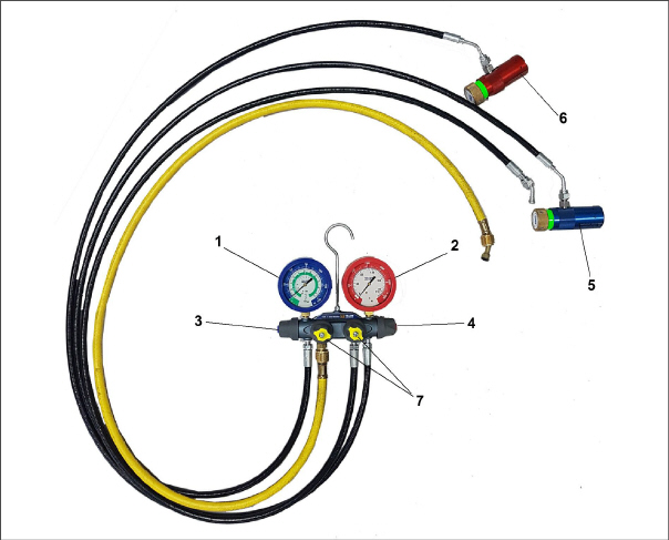
The service gauge set (part # 07-00582-00) is used to determine system operating pressure, add refrigerant charge, and to equalize or evacuate the system. See Figure 7.1.
3)Suction Hand Valve (low side)
4)Discharge Hand Valve (high side)
6)Discharge Coupling (high side)
7)Utility
hoses:
- yellow 3/8” (faster evacuation)
- black 1/4”
- - - - -
Only use manifold gauge sets designed and manufactured for R-744 (CO2) on these units.
There are two service connections on the NaturaLINE unit. See Section 3.1.4 for component locations.
•For PIDs lower than NT5010, the connections are service fittings. The suction (low side) service fitting is located on the bell housing of the compressor, the discharge (high side) service fitting is located under the Filter Drier.
•For PIDs NT5010 and higher, the connections are service valves. The suction (low side) service valve is mounted on a bracket above the compressor, the discharge (high side) service valve is located under the Filter Drier.
To completely open the system the Economizer Solenoid Valve (ESV), Unloader Solenoid Valve (USV), and High Pressure Expansion Valve (HPXV) must be opened. See Section 7.2.4 for procedure.
7.2.2Connecting Service Gauges
Procedure for Units with Service Fitting:
1.Verify that the discharge and suction hand valves on the gauge set are fully closed by turning the knobs clockwise.
2.Before starting to attach the gauge set, check that the coupling connectors are clean and that both O-ring seals are correctly seated into their grooves at the bottom of the connector.
3.Remove the suction service connection access cap.
4.Connect the blue field service coupling (low side) to the suction service fitting. Check that the coupling is locked into place by lightly pulling back on it.
5.Turn the blue coupling knob clockwise to read (low side) system pressure on the gauge.
6.Remove the discharge service fitting access cap.
7.Connect the red field service coupling (high side) to the discharge service fitting. Check that the coupling is locked into place by lightly pulling back on it.
8.Turn the red coupling knob clockwise to read (high side) system pressure on the gauge.
9.Perform any required maintenance.
10.If any component changes are required, the system must first be evacuated. See Section 7.2.4.
Procedure for Units with Service Valves:
1.Verify that the discharge and suction hand valves on the gauge set are fully closed by turning the knobs clockwise.
2.Remove the suction service valve stem cap and check that the valve is backseated.
3.Remove the access valve cap.
4.Connect the blue hose (low side) to the access valve.
5.Slightly mid-seat the suction service valve to read (low side) system pressure on the gauge.
6.Remove the discharge service valve stem cap and check that the valve is backseated.
7.Remove the access valve cap.
8.Connect the red hose (high side) to the access valve.
9.Slightly mid-seat the discharge service valve to read (high side) system pressure on the gauge.
10.Perform any required maintenance.
11.If any component changes are required, the system must first be evacuated. See Section 7.2.4.
Procedure for Units with Service Fittings:
1.If the unit is running, turn it off by moving the Start-Stop switch (ST) to the OFF position.
2.Turn the low side field service coupling knob counterclockwise to close the system off to the gauges.
3.Turn the high side field service coupling knobs counterclockwise to close the system off to the gauges. If the high side coupling is closed first, then the contents of the high side hose can be dumped into the low side until the pressures equalize. After that, the low side can be closed from the system.
As the coupling knobs of the connector valves are being closed, a small pocket of CO2 refrigerant is isolated inside the connector which makes it difficult to remove. On the last turn of the valve, a vent opens which releases this trapped refrigerant.
4.With both service couplings closed, connect a hose to the center port of the manifold gauge set.
5.Make sure the open end of the hose is pointed in a safe direction, and slowly open the manifold gauge set high and low side hand valves to allow the hose pressure to be released.
Procedure for Units with Service Valves:
1.While the compressor is still ON, backseat the discharge (high side) service valve.
2.Midseat both hand valves on the manifold gauge set and allow the pressure in the manifold gauge set to drawn down to low side pressure. This returns any liquid that may be in the high side hose to the system.
3.Backseat the suction (low side) service valve.
4.Backseat both field service couplings and frontseat both manifold hand valves.
5.Remove hoses / couplings from the access valves.
6.Install both service valve stem caps and service port caps (finger-tight only).
7.2.4Manually Opening Solenoid Valves and High Pressure Expansion Valve
During system evacuation and refrigerant charging, both solenoid valves (ESV, USV) and the High Pressure Expansion Valve (HPXV) must be open. This ensures the removal of pockets of refrigerant throughout the system, and allows a complete system evacuation and dehydration. All valves will be reset upon system start up.
For location of the ESV, USV, and HPXV, see Section 3.1.4.
Opening the Economizer Solenoid Valve / Unloader Solenoid Valve
1.Obtain a magnet tool (Carrier Transicold part # 07-00512-00) to assist in this procedure.
2.Remove the coil from the valve body.
3.Place the magnet over the valve stem, an audible click will be heard when the valve opens.
Opening the High Pressure Expansion Valve
1.Obtain a magnet tool (Carrier Transicold part # 14-00396-20) to assist in this procedure.
2.Remove the power head from the expansion valve body.
3.Place the magnet tool over the valve body and rotate the tool counter-clockwise. When the tool begins to chatter during rotation, it means that the valve is fully open.
4.After the valve has been opened, replace the power head. Make sure the power head is sitting on the stem correctly, the dimples on the stem need to be engaged.
7.2.5Removing Refrigerant Charge
Opening the Manifold Gauge Valve wide open quickly can cause excessive noise and possible loss of the system oil charge.
To service any component that is part of the pressurized system, it is required to first remove the refrigerant charge.
To completely open the system the Economizer Solenoid Valve (ESV), Unloader Solenoid Valve (USV), and High Pressure Expansion Valve (HPXV) must be opened. See Section 7.2.4.
1.Connect the service gauge, by following the procedure for Connecting Service Gauges. See Section 7.2.2. The gauge will show the system pressure.
2.Once the manifold gauge set is properly connected and open to the system, connect the utility hose to the center port of the manifold gauge set if not already connected.
3.Secure the utility hose and point in a safe direction.
4.Slowly open the low side and high side of the gauge set to release the refrigerant through the utility hose.
5.After all of the R-744 refrigerant charge has been released from the system and the gauges read 0 psi, close the manifold gauge set hand valves.
7.2.6Refrigerant Leak (Tightness) Test
Never use air or gases containing oxygen for leak testing or operating refrigerant compressors. Pressurized mixtures of air or gases containing oxygen can lead to explosion.
Use only R-744 refrigerant to pressurize the system. Any other gas or vapor will contaminate the system, and require additional purging and evacuation of the system.
1.If the system is without refrigerant, charge the system with R-744 to full charge on the nameplate. See Section 7.2.8 for adding refrigerant.
2.Leak-check connections using an R-744 electronic leak detector (part # 07-00529-00). If AR-GLO dye has been added to the system, a UV torch can also be used to check for signs of leaks.
3.After identifying the leak location, remove the refrigerant charge. See Section 7.2.5.
4.Repair any leaks that were found.
5.Evacuate and dehydrate the unit. See Section 7.2.7. If the unit fails to pull down or maintain a vacuum, inspect the repair again.
6.Charge the unit. See Section 7.2.8.
7.After the repair is made to the unit (threaded joint or brazed), the joint MUST be leak tested using the R-744 electronic leak tester.
7.2.7Evacuation and Dehydration
The presence of moisture is detrimental to a refrigeration system can have many undesirable effects. The most common are copper plating, acid sludge formation, “freezing-up” of metering devices by free water, and formation of acids resulting in metal corrosion.
To completely open the system the Economizer Solenoid Valve (ESV), Unloader Solenoid Valve (USV), and High Pressure Expansion Valve (HPXV) must be opened. See Section 7.2.4.
1.Evacuate and dehydrate only after a refrigerant leak check has been performed and all leaks have been repaired.
2.Essential tools to properly evacuate and dehydrate the system include high side and low side manifold gauges, a vacuum pump (part # 07-00176-11) and an electronic vacuum gauge. Vacuum pump should be 8 cfm volume displacement (14 m/hr). If using the gauge set with a 3/8” yellow utility hose, it is faster to use the 3/8” hose if the pump is equipped with a 3/8” connection.
3.If possible, keep the ambient temperature above 15.6°C (60°F) to speed evaporation of moisture. If the ambient temperature is lower than 15.6°C (60°F), ice might form before moisture removal is complete. Heat lamps or alternate sources of heat may be used to raise the system temperature.
4.Remove all R-744 refrigerant from the system. See Section 7.2.5.
5.Connect both low side and high side manifold gauges to the vacuum pump and electronic vacuum gauge. See Figure 7.2, Figure 7.3 for evacuation diagram.
6.Test the evacuation setup for any connection leaks by closing the low side and high side service fittings and drawing a deep vacuum with the vacuum pump and gauge valves open. Shut off the pump and check to see if the vacuum holds. Repair leaks if necessary.
7.Open the low side and high side service fittings.
8.Start the vacuum pump. Evacuate the unit until the electronic vacuum gauge indicates 2000 microns. Close the electronic vacuum gauge and vacuum pump valves. Shut off the vacuum pump. Wait a few minutes to be sure the vacuum holds.
9.Break the vacuum with clean dry CO2 (R-744) refrigerant. Raise system pressure to roughly 0.14 bar (2 psig), monitoring it with the compound gauge.
10.Evacuate unit to 500 microns.
11.Close the electronic vacuum gauge and vacuum pump valves. Shut off the vacuum pump. Wait five minutes to see if vacuum holds. This procedure checks for residual moisture and/or leaks.
12.With a vacuum still in the unit, the refrigerant charge may be drawn into the system from a refrigerant container on a weight scale.
Only use Refrigerant R-744 with a Purity level of 99.9% CO2. Refer to nameplate for required charge.
In cold ambient temperatures it may be necessary to raise the bottle pressure by warming the cylinder. This is accomplished by using a cylinder warmer or by moving the cylinder into warm ambient conditions.
To completely open the system the Economizer Solenoid Valve (ESV), Unloader Solenoid Valve (USV), and High Pressure Expansion Valve (HPXV) must be opened. See Section 7.2.4.
1.Evacuate the unit and leave in a deep vacuum. See Section 7.2.7.
2.Place the R-744 cylinder on a scale and connect the utility hose from the service gauge to the pressure regulator. See Figure 7.2, Figure 7.3 for Evacuation diagram.
3.With the supply valve closed on the regulator, open the valve on the cylinder. The gauge on the regulator will now show the R-744 cylinder pressure.
4.Purge the utility hose by partially unthreading the hose on the manifold gauge set and opening the supply on the regulator. Tighten the hose on the gauge and close the supply line.
5.Zero out the scale or note the starting weight.
6.Open the low side and high side hand valves by turning the knobs counterclockwise. See Figure 7.2, Figure 7.3 for evacuation diagram.
7.Allow the R-744 refrigerant to flow into the unit until the correct weight of refrigerant has been added as indicated by the scale.
8.If you are unable to get the full charge into the unit based on ambient conditions, the following additional steps should be taken:
a.Remove magnets and refit coils to ESV, USV and HPXV.
b.Close the high side hand valve on the manifold gauge set.
c.Turn the unit on. The suction side pressure will reduce and the unit will start to draw the remaining refrigerant into the system.
9.Close the low side service connection by turning the knob clockwise once desired charge is reached.
10.Close the valve on the R-744 cylinder and bleed out remaining pressure in the utility line by partially unthreading the hose.
11.Start the unit in cooling mode. Run for approximately 10 minutes to make sure the unit is cooling properly.
12.Remove the gauge set. See Section 7.2.3.
Figure 7.2 Refrigeration Evacuation & Charging Diagram - PIDs lower than NT5010
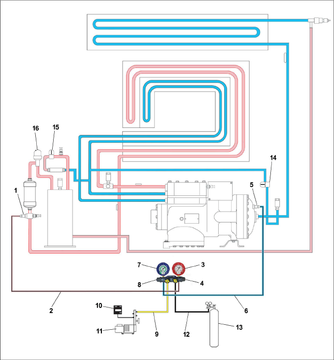
1)Discharge Service Fitting (high side)
4)Discharge Hand Valve (high side)
5)Suction Service Fitting (low side)
8)Suction Hand Valve (low side)
12)Utility Hose to R-744 Bottle
14)Unloader Solenoid Valve (USV)
15)Economizer Solenoid Valve (ESV)
16)High Pressure Expansion Valve (HPXV)
- - - - -
Figure 7.3 Refrigeration Evacuation & Charging Diagram - PIDs NT5010 and higher
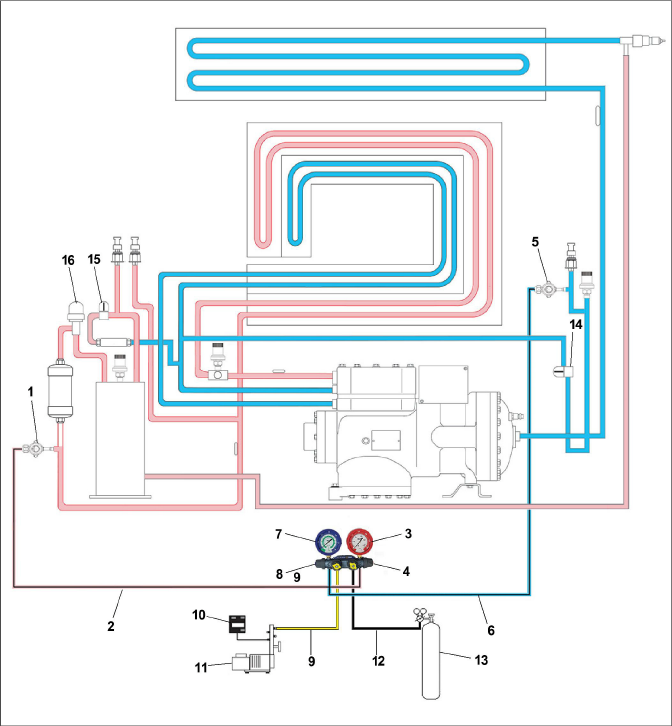
1)Discharge Service Valve (high side)
4)Discharge Hand Valve (high side)
5)Suction Service Valve (low side)
8)Suction Hand Valve (low side)
12)Utility Hose to R-744 Bottle
14)Unloader Solenoid Valve (USV)
15)Economizer Solenoid Valve (ESV)
16)High Pressure Expansion Valve (HPXV)
- - - - -
Make sure power to the unit is OFF and power plug disconnected before replacing the compressor.
Before disassembly of the compressor, be sure to relieve the internal pressure very carefully by slightly loosening the couplings to break the seal.
Compressor is shipped without oil in the compressor.
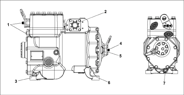
1)Flange Bolts
2)Terminal Block / Plate
3)Mounting Bolts
4)Flange Bolt
5)Suction Flange
6)Mounting Bolts
7)Oil Drain
- - - - -
7.3.1Removal and Replacement of Compressor
The service replacement of the compressor is sold without terminal box and cover, service connection, and Suction Pressure Transducer. The customer should retain these components for use on replacement compressor.
1.Turn the unit Start-Stop switch (ST) and unit Circuit Breaker (CB-1) Off.
2.Disconnect power to the unit.
3.Remove all refrigerant from the unit. See Section 7.2.5.
4.Locate the compressor terminal box. Tag and disconnect the wiring from the compressor terminals and remove the compressor terminal box. The terminal box will be used on the new compressor.
5.Loosen the compressor flange mounting bolts, break the seal and then remove the bolts.
6.Remove the compressor mounting bolts.
7.Remove the compressor and mounting plate (if compressor has a plate). See Section 3.2 for weight of compressor.
8.Remove the Suction Pressure Transducer (SPT) from compressor and check operation of switch. See Section 7.5.1. The SPT will be used on the new compressor.
9.Remove service fittings from the compressor. The service fittings will be used on the new compressor.
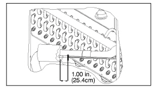
10.Place the compressor in a position where it will be convenient to drain the oil. Remove the oil drain plug (see Figure 7.4) and allow the oil to drain out slowly. The compressor will need to be angled to remove all the oil.
11.Measure the amount of oil drained from the compressor.
12.Add four mls. of AR-GLO 5E dye to the new replacement compressor oil.
13.Pour the equivalent amount of new oil into the suction side flange of the new compressor. See Figure 7.4. The compressor suction side may need to be elevated for better angle to pour oil in.
When installing service fittings and the Suction Pressure Transducer, a new O-ring must be installed with each. See Section 7.4 for instructions on installing the O-rings.
14.Install the service fittings with new O-rings on the replacement compressor and torque to 27 Nm (20 ft-lb).
15.Install the SPT with a new O-ring on the replacement compressor and torque to 27 Nm (20 ft-lb).
16.Install the replacement compressor in the unit.
17.Install the compressor mounting bolts and torque to 22.6 Nm (16.67 ft-lb).
18.If replacement compressor has mounting plate, install the compressor plate mounting bolts and torque to 22.6 Nm (16.67 ft-lb).
19.Connect the junction box to the replacement compressor and use the terminal wiring kit to rewire the compressor. Follow the instructions included with the kit.
20.Install the junction box cover.
21.Install the compressor flanges with new metal gaskets.
22.Install the flange mounting bolts and torque to 36.61 Nm (27 ft-lb).
23.Connect the high side and low side service gauges to the discharge and suction service fittings. See Section 7.2.2.
24.Dehydrate and evacuate the system to 500 microns (75.9 cm Hg vacuum = 29.90 inches Hg vacuum). See Section 7.2.7.
25.Charge the unit with refrigerant. See Section 7.2.8.
26.After the unit has been fully charged, remove the service gauges. See Section 7.2.3.
27.Start the unit and check operation.
28.If the compressor is equipped with a sight glass, the oil level should be between 1/4 and 3/4 of the sight glass while operating.
29.Clean the area below the foot of the compressor with local cleaner and install the icing label on the frame in front of the compressor (part # 62-66170-00).
This procedure is intended for all O-ring installations for this unit. A Pressure Relief Valve (PRV) is used for illustration purposes in this procedure.
1.Place electrical tape around the threads of the component to protect the O-ring from damage during installation. See Figure 7.5.
2.Apply a small amount of Super O-lube to the O-ring, making sure to coat the entire surface. See Figure 7.6.
3.Slide the O-ring over the tape and onto the component. See Figure 7.7.
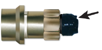
4.Remove electrical tape. See Figure 7.8.
Figure 7.5 O-Ring - Electrical Tape
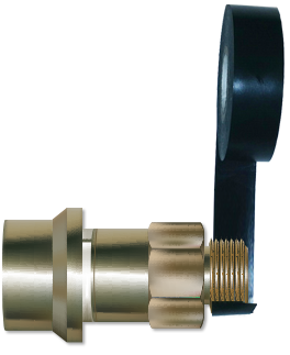
Figure 7.6 O-Ring - Apply Super O-lube
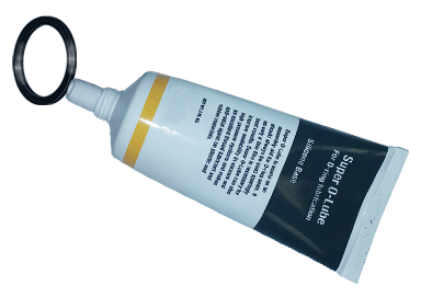
Figure 7.7 O-Ring - Slide On O-Ring
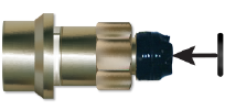
Figure 7.8 O-Ring - Remove Electrical Tape
7.4.2Adding Loctite 55 Thread Sealing Cord
On completion of the O-ring installation for components: Flash Tank Pressure Transducer (FPT), Discharge Pressure Transducer (DPT) and the high side coupling, add Loctite 55 thread sealing cord by following the procedure below.
1.Cut 7.5 cm (3 inch) of cord length from the Loctite 55 tube.
2.Twist the cord between the fingers to prevent fraying, rotate fingers in opposite directions. See Figure 7.9.
3.Locate the 3rd and 6th thread on the fitting. See Figure 7.10.
4.Wrap Loctite 55 cord around the transducer starting on the 3rd thread and end at the 6th thread in clockwise direction, overlap is not necessary but two full threads need to be covered and seated within the threads. See Figure 7.11, Figure 7.12.
5.The cord should be in contact with the threads without any loose ends, trimming off any excess. See Figure 7.13.
6.Hand tighten the transducer until the cord is fully rolled in the fitting. No part of the cord should be seen pushed out of the fitting thread. See Figure 7.14.
7.Torque to 9.5Nm - 10.8Nm (7 - 8 ft-lb).
Figure 7.9 Loctite 55 - Twist Cord
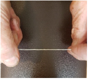
Figure 7.10 Loctite 55 - Locate Threads
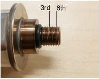
Figure 7.11 Loctite 55 - Wrap Cord
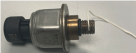
Figure 7.12 Loctite 55 - Wrap Cord
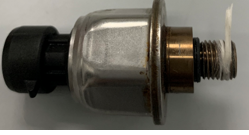
Figure 7.13 Loctite 55 - Trim Excess Cord
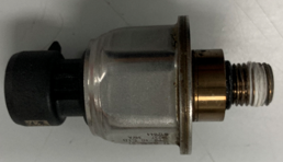
Figure 7.14 Loctite 55 - Tighten Transducer
7.5.1Checking a High Pressure Switch
1.Connect a set of gauges to the unit or read the unit pressure at code Cd14. If the pressure is below 100.6 bars (1430 psig), the switch should be closed. See Section 7.5.2.
2.Using an Ohm meter check the continuity of the switch. The ohm meter will indicate no resistance or the continuity light will be illuminated. If the switch is open, it should be replaced. See Section 7.5.2.
7.5.2Replacing a High Pressure Switch
The High Pressure Switch (HPS) is located on the 2nd stage discharge connection. See Figure 3.5.
1.Remove the refrigerant charge from the unit. See Section 7.2.5.
2.Disconnect wiring from the switch to be replaced.
3.Remove the High Pressure Switch (HPS) by turning the assembly counterclockwise.
4.See Section 7.4 for installation of O-ring on High Pressure Switch (HPS).
5.Install a new High Pressure Switch (HPS) and then run P-7 to confirm the settings for the switch are correct.
6.Evacuate and dehydrate the system. See Section 7.2.7.
7.Recharge the system. See Section 7.2.8.
8.Start the unit, and then verify refrigeration charge.
7.6.1Replacing a Pressure Transducer
For location of the pressure transducers, see Section 3.1.4.
1.Remove the refrigerant charge from the unit. See Section 7.2.5.
2.Disconnect wiring from the pressure transducer.
3.Remove the pressure transducer by turning the assembly counterclockwise.
4.See Section 7.4 for installation of the O-ring on the pressure transducer.
5.Install a new pressure transducer.
6.Evacuate and dehydrate the system. See Section 7.2.7.
7.Recharge the system. See Section 7.2.8.
8.Start the unit, and then verify refrigeration charge.
The transducer should be used within 48 hours after cord wrapping.
There are three Pressure Relief Valves (PRV) located in the NaturaLINE unit. See Section 3.1.4 for location.
7.7.1Replacing a Pressure Relief Valve
There are no serviceable parts on a pressure relief valve (PRV). Attempting to repair or alter the PRV is not permitted. If the PRV has released pressure, the entire PRV must be replaced.
1.Remove the refrigerant charge from the unit. See Section 7.2.5.
2.Remove the pressure relief valve.
3.Verify no contaminants have entered into the orifice.
4.See Section 7.4 for installation of an O-ring on the pressure relief valve.
5.Install a new pressure relief valve using correct torque. Wrench on 1-1/8” hexagon flats only, do not wrench on round surfaces. See Section 3.3 for torque requirements.
6.Evacuate and dehydrate the system. See Section 7.2.7.
7.Recharge the system. See Section 7.2.8.
8.Start the unit, and then verify refrigeration charge.
7.8Gas Cooler / Intercooler Coil
The Gas Cooler consists of the Gas Cooler and the Intercooler sections.
Keep the coil clean to maximize air flow and maintain proper heat transfer. If cleaning is required, use fresh water.
Use low water pressure when cleaning coils to avoid damage.
7.8.2Gas Cooler Coil Replacement
Do not open the Gas Cooler fan grille before turning power OFF and disconnecting power plug.
1.Remove the refrigerant charge from the unit. See Section 7.2.5.
2.Remove the Gas Cooler fan grille and side panels.
3.Unsolder the (2) Intercooler and (2) Gas Cooler lines.
4.Remove the coil mounting hardware and remove the coil assembly.
5.Install the replacement coil and mounting hardware.
6.Solder the Intercooler and Gas Cooler connections.
7.Leak-check the unit coil connections. See Section 7.2.6.
8.Evacuate and dehydrate the system. See Section 7.2.7.
9.Recharge the system. See Section 7.2.8.
10.Secure fan grille and any panels that may have been removed.
7.9Gas Cooler Fan and Motor Assembly
Do not open Gas Cooler fan grille before turning power OFF and disconnecting power plug
The Gas Cooler fan rotates counterclockwise as viewed from front of unit. The fan pulls air through the coil, and discharges air horizontally through the front of the unit. To replace the motor assembly:
1.Remove the Gas Cooler fan grille.
2.Loosen the two set screws on fan. (Thread sealer has been applied to set screws at installation.)
Do not pull or pry from the outer edge of the fan as this may damage the fan.
3.Remove the fan assembly.
4.Unplug the wiring connector.
5.Mark the location of the fan motor and keep the hardware in the same location for reassembly.
6.Remove motor mounting hardware and replace the motor. It is recommended that new locknuts be used when replacing the motor.
7.Connect the wiring connector.
8.Install the fan loosely on the motor shaft (hub side in). DO NOT USE FORCE. If necessary, tap the hub only, not the hub nuts or bolts. Apply “Loctite H” to the (2) fan set screws. Adjust the fan within the venturi so that the outer edge of the fan is within 2.0 +/- 0.07 mm (0.08” +/- 0.03”) from the outside of the orifice opening. Spin the fan by hand to check clearance.
9.Secure the fan grille and any panels that may have been removed.
Do not touch the Filter Drier to check for temperature difference while the unit is operating. Refer to troubleshooting for when to replace the Filter Drier due to restriction.
The Filter Drier should be replaced any time the system is opened up for service.
Replacing the Filter Drier:
1.Remove the refrigerant charge from the unit. See Section 7.2.5.
2.Remove Filter Drier by loosening the compression fittings.
3.Install the new Filter Drier and tighten the compression fittings.Torque to 18.4-22.1 Nm (25-30 ft-lb).
4.Evacuate and dehydrate the system. See Section 7.2.7.
5.Recharge the system. See Section 7.2.8.
The evaporator section, including the coil, should be cleaned regularly. Restrictions in the evaporator coil restrict air flow through the coil and reduce heat transfer. The preferred cleaning fluid is fresh water or steam. Another recommended cleaner is Oakite 202 or similar, following manufacturer’s instructions.
The two drain pan hoses are routed behind the Gas Cooler fan motor and compressor. The drain pan line(s) must be open to ensure adequate drainage.
7.11.1Evaporator Coil Replacement
1.Remove the refrigerant charge from the unit. See Section 7.2.5.
2.With power OFF and power plug removed, remove the screws securing the panel covering the evaporator section (upper panel).
3.Disconnect the defrost heater wiring.
4.Remove the mounting hardware from the coil.
5.Unsolder the two coil connections, one at the distributor and the other at the coil header.
6.Disconnect the Defrost Temperature Sensor (DTS), the Heat Termination Thermostat (HTT) and ground wire from the center tube sheet. See Figure 3.2.
7.Remove middle coil support.
8.After defective coil is removed from unit, remove defrost heaters and install on replacement coil.
9.Install coil assembly by reversing above steps.
10.Leak check evaporator coil connections.
11.Evacuate and dehydrate the system. See Section 7.2.7.
12.Recharge the system. See Section 7.2.8.
Figure 7.15 Heater Arrangement
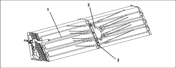
1)Heater Element
2)Bracket
3)Retainer
- - - - -
7.12.1Evaporator Heater Removal and Replacement
The heaters are wired directly back to the contactor and if a heater failure occurs during a trip, the heater set containing that heater may be disconnected at the contactor.
The next Pre-trip will detect that a heater set has been disconnected and indicate that the failed heater should be replaced.
7.12.2Megger Testing the Heaters
Always turn OFF the unit circuit breakers, disconnect the main power supply, and perform Lock Out / Tag Out before working on moving parts.
All of the checks performed during this procedure should be carried out using a 500v Meg-ohm tester.
1.Connect the ground wire from the insulation tester to a fixed ground point, preferably the ground plate in the control box.
2.At the load side of the heater contactor, check the insulation resistance to ground.
If readings are > 2 Mohm, then the heaters are operating properly and no action is needed.
If readings are < 1 Mohm, then the faulty heater needs to be identified. Proceed to step 3 for units with a heater access panel or step 4 for units without a heater access panel.
If readings are between 1 and 2 Mohm, then the heaters need to be re-tested with the following steps:
a.Reconnect the unit to power and power the unit on.
b.Set the unit set point to a minimum of 10°C higher than the current temperature of the container. Allow the unit to go into heat mode, reach the temperature set point and maintain for 10-15 minutes.
c.Power the unit off. Allow the unit to cool to ambient temperature.
d.Connect the ground wire from the insulation tester to a fixed ground point, preferably the ground plate in the control box.
e.At the load side of the heater contactor, check the insulation resistance to ground.
If readings are > 1 Mohm, then the heaters are operating properly and no action is needed.
If readings are < 1 Mohm, then the faulty heater needs to be identified. Proceed to step 3 for units with a heater access panel or step 4 for units without a heater access panel.
3.Identify the faulty heater(s) for units with a heater access panel:
a.Open the access panel and cut out all wire splices to isolate all heaters inside of the unit.
b.Repeat the Megger test on each individual heater. Connect the ground clip to the outer metal sheath of the heater and the test clip to one of the wires from the same heater.
c.Replace any heater where the readings are < 1 Mohm.
4.Identify the faulty heater(s) for units without a heater access panel:
a.Remove all six connections from the Heater (HR) contactor load side, which splits the six heaters into three separate pairs.
b.Identify the following three wires: DHTL, DHML, DHBL. There is one from each load connection.
c.Repeat the Megger test on each pair of heaters to identify the faulty heater pair. Connect the ground clip from the insulation tester to a fixed ground point on the unit, preferably the ground plate in the control box. Connect the test clip to one of the wires stated above.
d.Test all three wires and replace any heater pair that has readings < 1 Mohm.
5.If the unit is loaded, and the heater can not be immediately replaced, perform the following steps:
a.Identify the wire at the opposite end of the faulty heater pair: DHTL - DHTR, DHML - DHMR, DHBL - DHBR.
b.Isolate the two wires.
c.Reconnect the remaining good wiring pairs to their original connections.
d.The unit will fail the PTI test P1-0 at the next pre-trip inspection. Repair action can be taken at that time.
6.If the unit is empty, replace the faulty heater:
Always turn OFF the unit circuit breakers, disconnect the main power supply, and perform Lock Out / Tag Out before working on moving parts.
a.With the heater pair identified, remove the upper back panel inside the container.
b.Identify the center point connection for the heater pair (black wiring from heaters) either against the unit back wall or in the wiring loom.
c.Cut the splice to separate the two heaters.
d.Carry out a Megger check on the two heaters in the same way as for units with heater panel. Replace any heater where the Megger readings are < 1 Mohms.
If all heaters are above the acceptable limit with the wiring disconnected, then this indicates that the fault was in one or more of the wire splices that were removed.
e.Remove the hold-down clamp securing the heater(s) to the coil.
f.Verify that the heaters are not hot before handling them.
g.Lift the bent end of the heater (with the opposite end down and away from the coil). Move the heater to the side enough to clear the heater end support and remove.
h.To install heater, reverse steps.
i.Reconnect all wiring using new splices and heat shrink where needed. The heat shrink MUST have a 'melt-able' liner to ensure that the connections are properly sealed when shrunk. This can be seen as a 'Ring' of melt liner pushed from under the heat shrink at each end of the shrink tube.
Failure to use melt liner heat shrink allows moisture to 'wick' up under the heat shrink and cause a leakage path.
7.13Evaporator Fan And Motor Assembly
The evaporator fans circulate air throughout the container by pulling air in the top of the unit. The air is forced through the evaporator coil where it is either heated or cooled and then discharged out the bottom of the refrigeration unit into the container. The fan motor bearings are factory lubricated and do not require additional grease.
Figure 7.16 Evaporator Fan Assembly
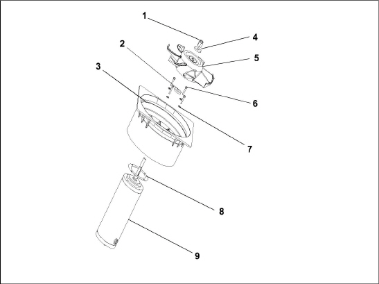
1)Locknut, 5/8-18
2)Flat Washer, 5/8
3)Stator
4)Flat Washer, 5/8
5)Impeller Fan
6)Screw, 1/4
7)Flat Washer, 1/4
8)Mylar Protector
9)Evaporator Motor
- - - - -
7.13.1Replacing the Evaporator Fan Assembly
Always turn OFF the unit circuit breakers, disconnect the main power supply, and perform Lock Out / Tag Out before working on moving parts.
1.Remove the upper access panel (see Figure 3.2) by removing mounting bolts and TIR locking device. Reach inside of unit and remove the Ty-Rap securing the wire harness loop. Disconnect the connector by twisting to unlock and pulling to separate.
2.Loosen four 1/4-20 clamp bolts that are located on the underside of the fan deck at the sides of the fan assembly. Slide the loosened clamps back from the fan assembly.
3.Slide the fan assembly out from the unit and place on a sturdy work surface.
7.13.2Disassemble the Evaporator Fan Assembly
1.Secure the fan blade so that it cannot turn. Then, loosen the 5/8-18 shaft nut by turning the 5/8-18 nut counter-clockwise. See Figure 7.16.
2.Use a universal wheel puller and remove the fan from the shaft.
3.Remove the washers and key.
4.Remove the four 1/4-20 x 3/4 long bolts that are located under the fan that support the motor and stator housing.
5.Remove the motor and plastic spacer.
7.13.3Assemble the Evaporator Fan Assembly
1.Assemble the motor and plastic spacer onto the stator.
When removing the black nylon evaporator fan blade, care must be taken to assure that the blade is not damaged. In the past, it was a common practice to insert a screwdriver between the fan blades to keep it from turning. This practice can no longer be used, as the blade is made up of a material that will be damaged. It is recommended that an impact wrench be used when removing the blade. Do not use the impact wrench when reinstalling, as galling of the stainless steel shaft can occur.
2.Apply Loctite to the 1/4-20 x 3/4 long bolts and torque to 7.9Nm (70 in-lb).
3.Place one 5/8 flat washer on the shoulder of the fan motor shaft. Insert the key in the keyway and lubricate the fan motor shaft and threads with a graphite-oil solution (such as Never-seez).
4.Install the fan onto the motor shaft. Place one 5/8 flat washer with a 5/8-18 locknut onto the motor shaft and torque to 40 foot-pounds.
5.Install the evaporator fan assembly in reverse order of removal. Torque the four 1/4-20 clamp bolts to 7.9Nm (70 in-lb). Connect the wiring connector.
6.Replace access panel making sure that panel does not leak. Make sure that the TIR locking device is lockwired.
7.14Evaporator Section Cleaning
Containers and Container units that are exposed to certain fumigants may develop visible surface corrosion. This corrosion will show up as a white powder found on the inside of the container and on the reefer unit evaporator stator and fan deck.
Analyses by Carrier Transicold environmental specialists have identified the white powder as consisting predominantly of aluminum oxide. Aluminum oxide is a coarse crystalline deposit most likely the result of surface corrosion on the aluminum parts within the container. If left untreated over time, it may build up in thickness and eventually flake as a lightweight white powder.
The surface corrosion of aluminum is brought about by exposure to chemicals such as sulfur dioxide and possibly other fumigants that are commonly used for fumigation and protection of some perishable cargo such as grapes, for example. Fumigation is the process by which a chemical is released into an enclosed area to eliminate infestations of insects, termites, rodents, weeds and soil-born disease.
Typically any aluminum oxide that becomes detached from evaporator fan stators will be blown into the wet evaporator coil where it will be caught and then flushed out of the unit during routine defrost cycles.
However, it is still highly recommended that after carrying cargo subject to fumigation procedures, that the inside of the unit be thoroughly cleansed prior to reuse.
Carrier Transicold has identified a fully biodegradable and environmentally safe alkaline cleaning agent (Tri-Pow’r® HD) for the unit. This will assist in helping to remove the corrosive fumigation chemicals and dislodging of the corrosive elements.
This cleaner is available from the Carrier Transicold Performance Parts Group (PPG) and can be ordered through any of the PPG locations; Part Number NU4371-88.
As a general safety precaution, before using this product, refer to and retain the Material Safety Data (MSDS) sheet.
Cleaning Guidelines:
•Use low water pressure when cleaning coils to avoid damage.
•Always wear goggles, gloves and work boots.
•Avoid contact with skin and clothing, and avoid breathing mists.
•When mixing, add water to the sprayer first, then the cleaner.
•ALWAYS provide for proper ventilation when cleaning indoor evaporator coils (rear doors must be open).
•Be aware of surroundings - food, plants, etc., and the potential for human exposure.
•Always read directions and follow recommended dilution ratios. More is not always better. Using non-diluted cleaner is not recommended.
Cleaning Procedure:
1.Remove the upper evaporator access panel inside of the unit.
2.Spray the surface with water before applying the cleaning solution. This helps the cleaner work better.
3.Liberally apply the prepared cleaner solution (5 parts water and 1 part cleaner).
4.Allow the cleaner to soak in for 5 to 7 minutes.
5.Assess area for rinsing. Follow all local regulations regarding disposal of waste water.
6.Thoroughly rinse the cleaner and surrounding area, floor, etc. When rinsing where heavy foaming solution is present, it is very important to take the time to thoroughly rinse the equipment and surroundings.
7.Always rinse the empty coil cleaner bottle, cap tightly and dispose of properly.
7.15Electronic Expansion Valve (EEV)
The Electronic Expansion Valve (EEV) is an automatic device which maintains required superheat of the refrigerant gas leaving the evaporator. For location of the Electronic Expansion Valve, see Figure 3.2.
The valve functions are:
a.Automatic response of refrigerant flow to match the evaporator load.
b.Prevention of liquid refrigerant entering the compressor. Unless the valve is defective, it seldom requires any maintenance.
7.15.1Removing an EEV or HPXV:
1.Turn unit power off and remove power from the unit.
2.Remove the coil (applies only to the HPXV).
3.Remove the refrigerant charge from the unit. See Section 7.2.5.
4.The preferred method of removing the valve is to cut the connection between the brazed section and the valve, using a small tube cutter. The valve can also be removed by un-brazing the connection. Remove valve.
7.15.2Installing an EEV or HPXV:
1.Make sure that there is no brazing material in the lines, and install the new valve.
2.When brazing in the new valve, the power head should be cooled with wet cloth.
3.Make sure that the HPXV coil is snapped down fully, and the coil retention tab is properly seated in one of the valve body dimples.
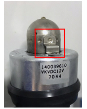
Important Notes:
•Retention tab is not visible with the coil boot fitted as shown in Figure 7.17.
•For better visualization, see Figure 7.18 for correct position of the coil with the retention tab sited in one of the valve body dimples.
•Do not remove the coil boot from the valve.
4.Grab and rotate the coil for approximately 1/4 turn in either direction (see Figure 7.17) and make sure that you can feel the clicking as the coil retention tab is moving from dimple to dimple.
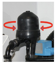
Figure 7.18 HPXV Valve Body Dimples
5.Apply the blue dot on the unit side wall next to the coil indicating that the coil has been inspected and is seated correctly on the valve body.
6.If a coil is seated incorrectly on a loaded unit once it has been seated properly, power cycle the unit. This enables the controller to reset the valve to 0% to ensure proper operation going forward.
7.Replace the Filter Drier. See Section 7.10.
8.Evacuate and dehydrate the system. See Section 7.2.7.
9.Recharge the system. See Section 7.2.8.
10.Check unit operation by running Pre-trip. See Section 4.7.
The humidity sensor is an optional component that allows setting of a humidity setpoint in the controller. In dehumidification mode, the controller will operate to reduce internal container moisture level.
7.16.1Checking the Operation of the Humidity Sensor
This procedure is to be performed in an effort to ease the troubleshooting of the humidity sensor. When performing this procedure and while working on the unit, always follow the proper lockout/tagout procedures.
Items Required:
•One 7/16” socket wrench or nut driver.
•One 1/4” socket wrench or nut driver.
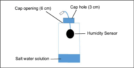
•One clean, clear water bottle with a minimum 6 cm (2.5 in) opening and capacity to hold 500 ml (16.9 oz).
•100 ml (3.4 oz) of fresh water - distilled if available.
•50 gm of Salt (NaCl).
Procedure:
1.Remove the left Upper Fresh Air Makeup Vent panel.
2.Remove the humidity sensor from the mounting hardware and bring to the front of the access panel.
3.Disconnect the humidity sensor from the harness.
4.Drill a 3 cm (1.25 in) hole in the cap of a bottle.
5.Pour approximately 100 ml (3.4 oz) of water into the empty clean bottle.
6.Add salt to the water until it is present at the bottom of the bottle.
7.Cap the bottle and tape over the drilled hole.
8.Shake the bottle until the salt dissolves and water is saturated.
To ensure saturation, add additional salt until it settles at the bottom without dissolving while shaking.
9.Remove the cap and insert the humidity sensor into the bottle through the bottle opening and pull the connector back through the drilled hole in the cap. Then, secure the cap and seal the wire going through the cap.
Make sure that the sensor is not at all in contact with the salt water.
10.Allow the saturated salt mixture to settle for approximately ten minutes.
11.Reconnect the humidity sensor to the harness and power the reefer unit on.
12.Press the CODE SELECT key on the keypad.
13.Use the Arrow keys until “Cd17” is displayed then press the ENTER key.
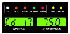
14.This displays the humidity sensor reading. Verify the reading is between 60% and 85% relative humidity.
15.If the humidity sensor display is outside of this range, reconfirm the salt mixture and retest. If not in range, replace the sensor at the next opportunity.
16.Wipe clean and reinstall the humidity sensor and access panel. Torque the access panel hardware to 69 kg-cm (60 in.-lbs.) using a crossing pattern similar to the numbering below.
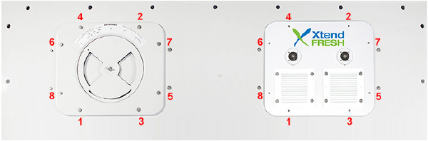
17.If the panel gasket is damaged and needs to be replaced, use the following part numbers:
•42-00296-01: Standard Panel Gasket
•42-00823-00: XtendFRESH Panel Gasket
7.17Economizer Solenoid Valve, Unloader Solenoid Valve
The procedures for removing / replacing the ESV and removing / replacing the USV are the same.
For location of the Economizer Solenoid Valve and the Unloader Solenoid Valve, see Figure 3.3.
7.17.1Removing / Replacing the ESV or USV Coil
1.Remove the valve coil from the valve. See Figure 7.19.
2.Cut the cable approximately 3 inches (75 mm) from the coil.
3.Connect the new coil wires using butt-splices and heat-shrink tubing.
4.Replace the coil on the valve, make sure that the coil is fully seated.
7.17.2Removing / Replacing the ESV or USV
1.Turn unit power off and remove power from the unit.
2.Remove the refrigerant charge from the unit. See Section 7.2.5.
3.Remove the valve coil from the valve. See Figure 7.19.
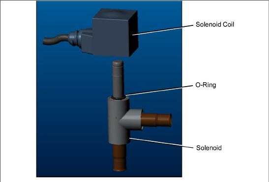
Figure 7.19 Coil View of Economizer Solenoid Valve (ESV)
4.VALVE REMOVAL: The preferred method of removing the solenoid valve is to cut the connection between the brazed section and the valve, using a small tube cutter. The valve can also be removed by un-brazing the connection. Then remove the valve. Remove valve.
5.Fit the new solenoid valve into position and braze. Use a wet rag to keep valve cool whenever brazing.
6.Install the O-ring on the valve stem (provided). See Figure 7.19.
7.Press the coil onto the valve stem ensuring that it is pressed all the way down, engaging with the O-ring.
7.18Removing / Replacing the Flash Tank
The NaturaLINE unit is equipped with a flash tank. See Figure 3.3 for location.
There are no serviceable parts on the flash tank. Attempting to repair the flash tank or welding on the flash tank vessel is not permitted. If the flash tank should be damaged in any way the entire flash tank must be replaced.
Removing the Flash Tank:
1.Turn unit power off and remove power from the unit.
2.Remove the refrigerant charge from the unit. See Section 7.2.5.
3.Remove flash tank pressure relief valve.
4.Un-braze the tube connections.
5.Remove the bolts securing the flash tank to the unit (4 places).
6.Take out flash tank.
Installing the Flash Tank:
1.Bolt flash tank to the unit (4 places).
2.Braze only at the tube connections.
3.Install pressure relief valve with new O-ring onto flash tank. See Section 7.4.
4.Replace Filter Drier. See Section 7.10.
5.Evacuate and dehydrate the system. See Section 7.2.7.
6.Recharge the system. See Section 7.2.8.
7.Check unit operation by running Pre-trip. See Section 4.6.
The NaturaLINE platform must use the green label controller only (part number 12-55011).
Do not remove wire harnesses from module unless you are grounded to the unit frame with a static safe wrist strap.
Unplug all module connectors before performing arc welding on any part of the container.
The guidelines and cautions provided herein should be followed when handling the modules. These precautions and procedures should be implemented when replacing a module, when doing any arc welding on the unit, or when service to the refrigeration unit requires handling and removal of a module.
1.Obtain a grounding wrist strap (Carrier Transicold part number 07-00304-00) and a static dissipation mat (Carrier Transicold part number 07-00277-00). The wrist strap, when properly grounded, will dissipate any potential buildup on the body. The dissipation mat will provide a static-free work surface on which to place and/or service the modules.
2.Disconnect and secure power to the unit.
3.Place strap on wrist and attach the ground end to any exposed unpainted metal area on the refrigeration unit frame (bolts, screws, etc.).
4.Carefully remove the module. Do not touch any of the electrical connections if possible. Place the module on the static mat.
5.The strap should be worn during any service work on a module, even when it is placed on the mat.
7.19.2Controller Troubleshooting
A group of test points, TP1 - TP10, are provided on the controller for troubleshooting electrical circuits. See Figure 7.20 and schematic diagram in Section 8.
Use a digital voltmeter to measure AC voltage between TP’s and ground (TP9), except for TP8.
Figure 7.20 Controller Section of the Control Box
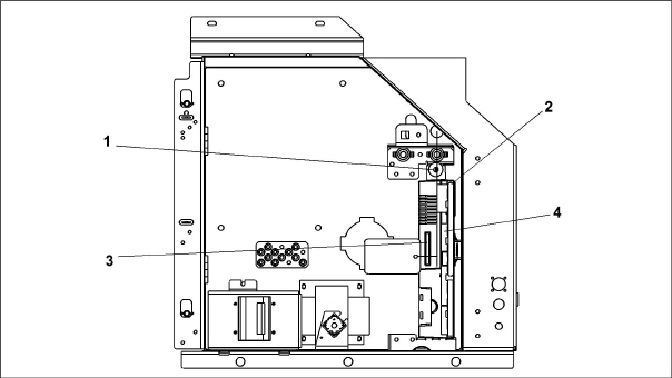
1)Mounting Screw
2)Controller
3)Controller Software Programming Port
4)Test Points
- - - - -
7.19.3Controller Programming Procedure
The unit must be OFF whenever a programming card is inserted or removed from the controller programming port.
Procedure for Loading Operational Software:
1.Place the Start-Stop switch (ST) to “0” to turn power off.
2.Insert the software / programming PCMCIA card into the programming port on the controller (see Figure 7.20). The PCMCIA card will contain the following (example) files:
•menuDDMM.ml3, this file allows the user to select a file/program to upload into the controller.
•cfYYMMDD.ml3, multi-configuration file.
3.Place the Start-Stop switch (ST) to “I” to turn unit power on.
4.The display will display the message “SEt UP”.
5.Press the Up or Down Arrow keys until the display reads “LOAd 57XX”. The XX represents the software revision.
6.Press the ENTER key.
7.The display will alternate between the messages “PrESS EntR” and “rEV 57XX”.
8.Press the ENTER key.
9.The display will show the message “Pro SoFt”. This message will last for up to one minute as the new software is loading.When software loading is complete, the display will show the message “Pro donE”.
If a problem occurs while loading the software, the display will blink the message “Pro FAIL” or “bad 12V”. Place the Start-Stop switch (ST) to “0” and remove the card.
10.Place the Start-Stop switch (ST) to “0” to turn unit power off.
11.Remove the PCMCIA card from the programming slot.
12.Place the Start-Stop switch (ST) to “I” to return the unit to normal operation.
13.On power up, the status LED will flash quickly and the display will remain blank as the controller loads the new software. This takes about 15 seconds. When complete, the controller will reset and power up normally.
14.Wait for the default display to appear: setpoint on the left, and control temperature on the right.
15.To confirm the correct software loaded, use the keypad to bring up function code Cd18.
Procedure for Loading Configuration Software:
1.Place the Start-Stop switch (ST) to “0” to turn power off.
2.Insert the software / programming PCMCIA card into the programming port on the controller (see Figure 7.20). The PCMCIA card will contain the following (example) files:
•menuDDMM.ml3, this file allows the user to select a file/program to upload into the controller.
•cfYYMMDD.ml3, multi-configuration file.
3.Place the Start-Stop switch (ST) to “I” to turn unit power on.
4.The display will display the message “SEt UP”.
5.Press the ENTER key on the keypad.
6.The display will read “ruN COnFG”.
If the display has blinking message “bAd CArd”, then the card is defective. Place the Start-Stop switch (ST) to “0” to turn power off and remove the card
7.Press the ENTER key.
8.The display module will go blank briefly and then display “6XX XXX”, based on the current operational software installed.
9.Press the Up or Down Arrow key until the display reads the desired model number.
10.Press the ENTER key.
11.When software loading has successfully completed, the display will show the message “COnFG donE”.
If the display has blinking message “Pro FAIL” or “bad 12V”, then a problem has occurred while loading the software. Place the Start-Stop switch (ST) to “0” to turn unit power off and remove the card.
12.Place the Start-Stop switch (ST) to “0” to turn unit power off.
13.Remove the PCMCIA card from the programming slot.
14.Place the Start-Stop switch (ST) to “I” to return the unit to normal operation.
15.To confirm the correct model configuration was loaded, use the keypad to bring up function code Cd20. The model displayed should match the last five digits of the model number listed on the unit nameplate (see Figure 2.1).
Procedure for Setting the Date and Time:
1.Place the Start-Stop switch (ST) to “0” to turn power off.
2.Insert the software / programming PCMCIA card into the programming port on the controller (see Figure 7.20). The PCMCIA card will contain the following (example) files:
•menuDDMM.ml3, this file allows the user to select a file/program to upload into the controller.
•cfYYMMDD.ml3, multi-configuration file.
3.Place the Start-Stop switch (ST) to “I” to turn unit power on.
4.The display will display the message “SEt UP”.
5.Press the ENTER key on the keypad.
6.The display will read “ruN COnFG”.
7.Press the Up or Down Arrow key until the display reads “SEt tIM”.
8.Press the ENTER key.
9.The display will show the date in YYYY MM-DD format. The day value will be blinking.
10.The date values are modified from right to left. Press the Up or Down Arrow key to increase or decrease the values. Press the ENTER key to confirm the value for the current field and move to the next value. Press the CODE SELECT key to modify the previous value.
11.After pressing ENTER to confirm the year value, the time will be displayed in HH MM format with the hours being in a 24 hour format. The minutes will be blinking.
12.The time values are modified from right to left. Press the Up or Down Arrow key to change the values. Press the ENTER key to confirm the value for the current field and move to the next value. Press the CODE SELECT key to modify the previous value.
13.After pressing ENTER to confirm the hour value, the display will return to “SEt tIM”.
14.Place the Start-Stop switch (ST) to “0” to turn power off.
15.Remove the PCMCIA card from the programming slot.
16.Place the Start-Stop switch (ST) to “I” to return the unit to normal operation.
Procedure for Setting the Container ID:
The characters will be preset to the container ID already on the controller. If none exist, the default will be AAAA0000000.
1.Place the Start-Stop switch (ST) to “0” to turn power off.
2.Insert the software / programming PCMCIA card into the programming port on the controller (see Figure 7.20). The PCMCIA card will contain the following (example) files:
•menuDDMM.ml3, this file allows the user to select a file/program to upload into the controller.
•cfYYMMDD.ml3, multi-configuration file.
3.Place the Start-Stop switch (ST) to “I” to turn unit power on.
4.The display will display the message “SEt UP”.
5.Press the ENTER key on the keypad.
6.The display will read “ruN COnFG”.
7.Press the Up or Down Arrow key until display reads “SEt Id”.
8.Press the ENTER key.
9.The display will show the first letter of the container ID.
10.Press the Up or Down Arrow key to increase or decrease the values. Press ENTER to confirm a value for the current field and move to the next value. Press CODE SELECT to modify a previous value.
11.When the last value is entered, press the ENTER key to enter the information to the controller. The display will return to “SEt Id”.
12.Place the Start-Stop switch (ST) to “0” to turn power off.
13.Remove the PCMCIA card from the programming slot.
14.Place the Start-Stop switch (ST) to “I” to return the unit to normal operation.
15.To confirm that the correct container ID was loaded, use the keypad to bring up function code Cd40.
7.19.4Removing and Installing a Module
Removal:
1.Disconnect all front wire harness connectors and move wiring out of way.
2.Remove the VIM module from the right side of the controller.
3.The lower controller mounting is slotted, loosen the top mounting screw and lift up and out. See Figure 7.20.
4.Disconnect the back connectors and remove module.
5.When removing the replacement module from its packaging, note how it is packaged. When returning the old module for service, place it in the packaging in the same manner as the replacement. The packaging has been designed to protect the module from both physical and electrostatic discharge damage during storage and transit.
Installation:
1.Install the module by reversing the removal steps.
2.Torque values for mounting screws are 2.26 Nm (20 in-lb). See Figure 7.20, item 2. Torque value for the connectors is 1.13 Nm (10 in-lb).
Standard Battery Location (Standard Cells):
1.Turn unit power OFF and disconnect power supply.
2.Slide bracket out and remove old batteries. See Figure 3.5, Item 8.
3.Install new batteries and slide bracket into control box slot.
Use care when cutting wire ties to avoid nicking or cutting wires.
Standard Battery Location (Rechargeable Cells):
1.Turn unit power OFF and disconnect power supply.
2.Disconnect battery wire connector from control box.
3.Slide out and remove old battery and bracket. See Figure 3.5, Item 8.
4.Slide new battery pack and bracket into the control box slot.
5.Reconnect battery wire connector to control box and replace wire ties that were removed.
Secure Battery Option (Rechargeable Cells Only):
1.Turn unit power OFF and disconnect power supply.
2.Open control box door and remove both the high voltage shield and clear plastic rain shield (if installed).
3.Disconnect the battery wires from the “KA” plug positions 14, 13, 11.
4.Using Driver Bit, Carrier Transicold part number 07-00418-00, remove the 4 screws securing the display module to the control box. Disconnect the ribbon cable and set the display module aside.
The battery wires must face toward the right.
5.Remove the old battery from the bracket and clean bracket surface. Remove the protective backing from the new battery and assemble to the bracket. Secure battery by inserting the wire tie from the back of the bracket around the battery, and back through the bracket.
6.Reconnect the ribbon cable to display and re-install the display.
7.Route the battery wires from the battery along the display harness and connect the red battery wire and one end of the red jumper to “KA14,” the other end of the red jumper wire to “KA11,” and the black wire to “KA13.”
8.Replace wire ties that were removed.
7.20.1Remove and Replace Variable Frequency Drive Cooling Fan
1.Turn unit off and disconnect power cord.
2.Remove the (8) screws that secure the VFD cover and remove the cover.
3.The VFD cooling fan is located on the right side of the VFD. Remove the (4) mounting screws that secure the fan assembly and grille to the VFD. See Figure 7.21.
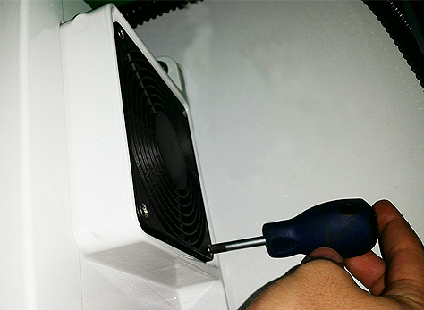
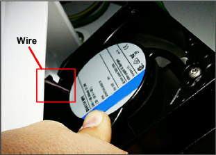
4.Remove the grille and fan assembly. While removing, rotate the fan assembly to in order to expose the wires. See Figure 7.22.
5.Cut the exposed VFD fan wires and remove the fan assembly.
6.Feed the cut wires through the opening at the back of the fan housing, this is where the new fan wires will be spliced to the existing wires.
1.Feed the new VFD fan wires through the opening at the back of the fan housing.
2.Butt splice and heat shrink the new fan wires and the existing wires.
3.Rotate the fan assembly and place it back into the fan housing so that the wires are located on top and completely tucked in behind the fan housing.
4.Place the grille over the fan and secure the fan assembly and grille with the (4) mounting screws.
5.Replace the VFD cover and secure in place with the (8) mounting screws.
6.Restore power to the unit and check the operation of the VFD fan.
7.20.2Variable Frequency Drive (VFD) Bypass
Variable Frequency Drive Electrical Hazard. After disconnecting from power supply, wait seven (7) minutes before servicing to allow capacitors to completely discharge.

If the VFD fails, the following procedure will bypass VFD control allowing the compressor to operate at one speed. This will restore limited unit functionality until the VFD can be repaired or replaced.
1.Turn the unit off and disconnect the power cord.
2.Wait a minimum of 7 minutes before servicing the VFD.
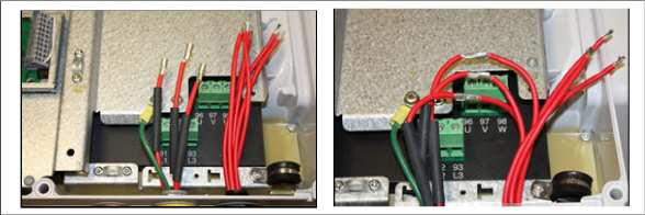
3.Remove the (8) screws that secure the VFD cover and remove the cover. The VFD Phase wiring will be visible in the lower right corner of the box. See Figure 7.23.
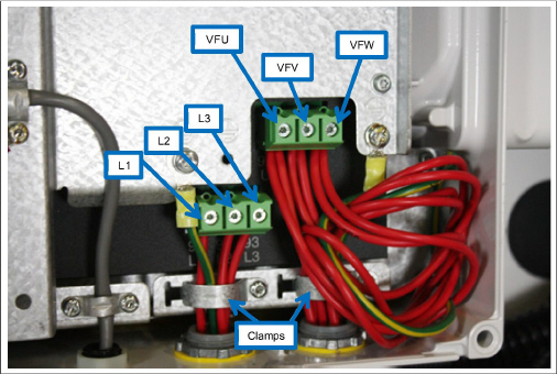
4.Remove wire harness clamps to allow wires to be worked on.
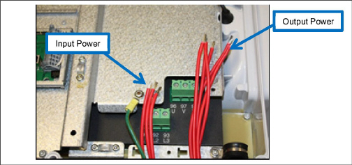
5.Disconnect the VFD input and output phase wires, leaving the ground wire attached.
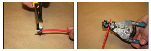
6.Cut the barrels off of the wires using wire cutters and strip back the insulation approximately 0.25” (6.35mm).
7.Locate the following wires to prepare for a butt splice connection.
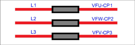
8.Position the heat shrink and crimp the electrical splice connector for all 6 wires mentioned above.
9.Locate the following wires to prepare for a two-to-one butt splice electrical connection.
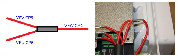
10.Using a hot air gun, shrink the heat shrink tube to insulate all of the electrical butt splice joints.
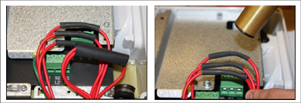
11.While heating the heat shrink tube for a two-to-one butt splice electrical connection, use a needle-nosed plier to crimp the heat shrink tube while heating.
The finished wires should look like the image below:
12.Install wire harness clamps and secure the wires using best practice to prevent damage.
13.Be sure that all the wires are within the VFD and replace the cover and secure with the eight (8) screws.
14.Power up the unit and go to Cd61 to activate the VFD Bypass mode.
15.While Cd61 is visible on the display, press and hold the ALT key for 2 seconds, then press ENTER with the ALT key still held down. This will lock the code. Press an arrow key to change from ‘OFF’ to ‘Act iV’ and press ENTER. Press ENTER a second time to lock and activate the limp home mode. Power cycle the unit to engage limp home mode. To unlock or reset to normal operation the same procedure must be followed. Cd61 will remain on the display until a valid selection is made, or is manually exited. If the state of limp home mode is modified, Cd61 will restart the unit after a 30 second hold off.
7.21Vent Position Sensor Service
The fresh air vent position sensor alarm (AL50) will occur if the sensor reading is not stable for four minutes or if the sensor is outside of its valid range (shorted or open). This can occur if the vent is loose or the panel is defective. To confirm a defective panel, assure that the wing nut is secure and then power cycle the unit. If the alarm immediately reappears as active, the panel should be replaced.
The alarm should immediately go inactive, check the 4-minute stability requirement. If the alarm reoccurs after the four minutes and the panel was known to have been stable, then the sensor should be replaced. In order to replace the Upper VPS, the panel must be removed and replaced with another upper fresh air panel equipped with VPS. If sensor is found to be defective then replace the panel or replace the VPS with kit number 74-66615-00.
Upon installation, a new Vent Position Sensor assembly requires calibration as follows:
1.Rotate the vent to the 0 CMH/ CFM position. Cd45 will automatically display.
2.Press the Enter key and hold for five seconds. After the enter key has been pressed the display will read “CAL” (for calibration).
3.Press the ALT MODE key and hold for five seconds. After the calibration has been completed, Cd45 will display 0 CMH / CFM.
7.22Temperature Sensor Service
Service procedures for the return recorder (RRS), return temperature (RTS), supply recorder (SRS), supply temperature (STS), ambient temperature (AMBS), defrost temperature (DTS), evaporator temperature (ETS), and compressor discharge temperature (CPDS) sensors are provided here.
The ice-water bath is a method for testing the accuracy of sensors by submerging the sensors in an insulated container with ice cubes or chipped ice, then filling voids between ice with water and agitating until the mixture reaches 0°C (32°F) measured on a laboratory thermometer.
Notes:
•Wherever possible, use a thermometer that is regularly calibrated by an accredited test lab. Contact your instrument representative if the reference thermometer is not showing correct readings.
•Always use a temperature measurement reference instrument which is of higher accuracy than the device checked – for example, a thermometer with a rated accuracy of +/- 0.2 °C should be used to check a device with a rated accuracy +/- 0.3 °C.
•A thermally insulated container, tub open to atmosphere and large enough to contain crushed ice and water should be used. The tub should be large enough to contain the unit’s sensor and the reference thermometer.
•Enough distilled water should be available to make ice cubes and to set up a proper and stable ice-water triple-point mixture. Prepare ice using distilled water.
•Pre-cool distilled water for testing.
Procedure:
1.Prepare a mixture of clean ice using distilled water in a clean insulated container. If possible, the person handling should be wearing latex gloves.
a.Crush or chip the ice to completely fill the container. The finer the ice particles, the more accurate the mixture.
b.Add enough pre-cooled distilled water to fill the container.
c.Stir the mixture for a minimum of 2 minutes to ensure water is completely cooled and good mixing has occurred.
d.The mixture should generally contain about 85% ice with the distilled water occupying the rest of the space.
e.Add more ice as the ice melts.
2.Stir the ice water slurry mixture to maintain a temperature of 0°C (32°F).
3.Constantly monitor the temperature of the ice water slurry with your reference thermometer. Ensure that the temperature of the bath has stabilized. The criterion for stability generally is to take two readings at 1 minute intervals, and the two readings should be 0°C (32°F).
7.22.2Sensor Checkout Procedure
This procedure is performed to verify the accuracy of a temperature sensor.
1.Remove the sensor and place it in a 0°C (32°F) ice-water bath. Refer to Ice Bath Preparation procedure.
2.Start the unit and check the sensor reading on the control panel. The reading should be 0°C (32°F). If the reading is correct, reinstall the sensor; if it’s not, continue with the next step.
3.Turn the unit OFF and disconnect the power supply.
4.Remove the controller to gain access to the sensor plugs. See Section 7.19.
5.Using the plug connector marked “EC” that is connected to the back of the controller, locate the sensor wires (RRS, RTS, SRS, STS, AMBS, DTS, or CPDS as required). Follow those wires to the connector and using the pins of the plug, measure the resistance. Values are provided in Table 7–2, Table 7–3.
Due to the variations and inaccuracies in ohmmeters, thermometers or other test equipment, a reading within 2% of the chart value would indicate a good sensor. If a sensor is defective, the resistance reading will usually be much higher or lower than the resistance values given.
7.22.3GDP Supply and Return Sensor Calibration
European Commission GDP (Good Distribution Practices) guidelines, which are used worldwide, call for the equipment used to control or monitor environments where medicinal products are stored or transported be calibrated in accordance with pharmaceutical shipper specifications, typically every six months or annually.
This procedure explains how to perform a GDP calibration of the supply (STS/SRS) and return (RTS/RRS) sensors using DataLINE software version 3.1 or higher. The calibration procedure should be conducted in pairs (STS/SRS, or RTS/RRS) and it is recommended to calibrate before the full pre-trip inspection.
Before removing the Supply or Return air sensors from the unit, turn the ON/OFF switch and circuit breaker to the OFF position. Disconnect the power plug from the unit. Follow proper lockout/tagout procedures to ensure the power cannot inadvertently be energized. It is important that all dismantling work is done and tools and personnel are away from the unit before powering on the unit for calibration.
When performing the Return Air Sensor calibration, disconnect both evaporator motors.
Before proceeding with the calibration procedure, ensure that controller software version is up to date (57xx) and DataLINE version 3.1 or higher is installed onto the download device. Only the latest DataLINE and controller software will allow users to carry out Good Distribution Practice (GDP) calibration. Do not downgrade the software after installing the latest software.
Before proceeding with the calibration procedure, it is recommended to check the sensors by running pre-trip P5-0. This test checks the sensor values. If the test fails, identify and correct the faulty sensor and rerun the test.
Tools Required:
•Socket screwdrivers set
•Phillips screwdriver
•Standard hand tools
•Interrogator cable
•Laptop with DataLINE 3.1 or above installed
•Clean insulated container for distilled water and ice
•A regularly calibrated reference thermometer, recommended to be of accuracy up to 2 decimal places
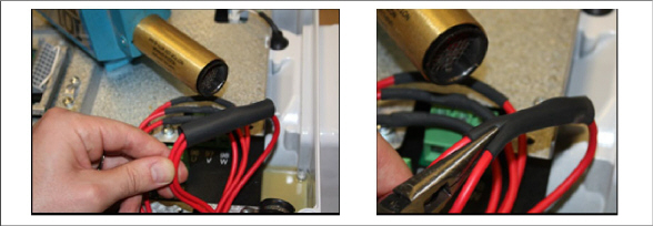
GDP Calibration, Removing Supply Sensors (STS/SRS) from Unit:
1.Locate the supply sensors cover assembly on the suction side of the compressor. Remove the two fasteners securing the cover of the sensors.
2.Remove the cover and rotate the supply air sensors, STS/SRS, in a clockwise direction and remove the sensors from the sensor housing.
GDP Calibration, Removing Return Sensors (RTS/RRS) from Unit:
1.Remove both front access panels from the unit by removing 8 fasteners from each panel. Save all hardware for re-installation.
2.On the right side, disconnect the fan motor wiring, loosen the fastener and remove (slide) the evaporator motor from the unit.
3.Loosen the fastener on the sensor bracket.
4.Cut all wire ties that are securing the sensors to the harness and remove sensor.
GDP Calibration, Perform Calibration:
1.Connect the interrogator cable to the interrogator port. Then, power on the unit.
Before powering on the unit, it is important to ensure that all dismantling work is done and tools are away and service personnel are not working on the unit at the time of power on.
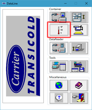
2.Open DataLINE version 3.1 or above. From the DataLINE launch pad, click on the Probe Calibration button to go to the Probe Calibration screen. A pop-up window will appear reminding the user to ensure proper ice bath temperature. Click OK to acknowledge.
Figure 7.24 DataLINE - Probe Calibration
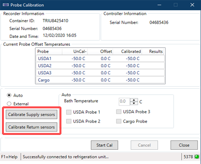
3.On the Probe Calibration screen, click on the Calibrate Supply sensors or Calibrate Return sensors button.
Figure 7.25 DataLINE - Calibrate Sensors Button
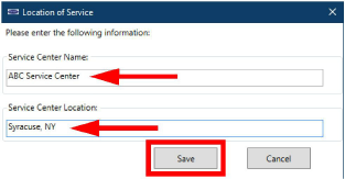
4.A Location of Service pop-up window will appear. In the appropriate fields, enter the Service Center Name and Service Center Location where the calibration is being performed. Then, click the Save button. A pop-up window will appear reminding the user to ensure proper ice bath temperature. Click OK to acknowledge and remember to maintain the Ice bath at 0°C (32°F).
Figure 7.26 DataLINE - Enter Service Information
5.Prepare the ice bath. Refer to the Ice Bath Preparation procedure.
Ensure that the set-up (i.e. ice bath, sensors, reference thermometer) has reached a stable state before beginning the calibration process. Ensure that the set-up is clean and the reference thermometer is regularly maintained and calibrated.
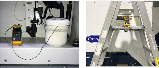
6.Place the ice bath in a location near sensors. For Return Sensors, place the ice bath on an elevated platform (ladder) of appropriate height.
7.Once temperature stability is ensured, submerge the sensors in the ice water slurry. Make certain that the sensors do not contact the container sides or bottom, or each other. Continuously stir the slurry mixture during calibration.
8.Ensure that the Ice bath is at 0°C (32°F) using the calibrated reference thermometer. Confirm that the sensor readings have stabilized and the sensors are within +/- 0.3°C (0.5°F). The readings can be taken from the Uncal column in the Current Probe Offset Temperatures table.
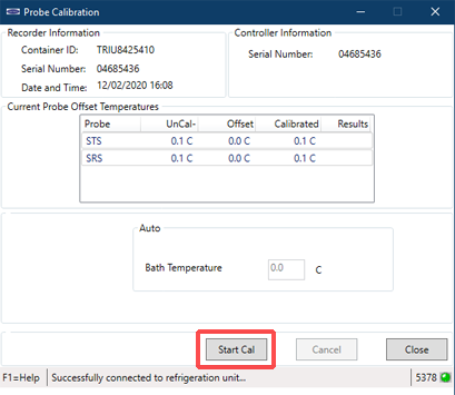
9.Then, after confirming the sensor readings have stabilized, click on the Start Cal button. After clicking Start Cal, the process begins automatically and will complete in less than 5 minutes. Continue to stir the ice bath during testing. Calibration will fail if the stability cannot be achieved or the sensor offset is greater than 0.3°C (0.5°F).
Figure 7.28 DataLINE - Start Cal Button
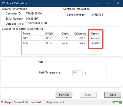
10.Once the calibration has completed, a pop-up will appear with the message Calibrate Complete. Click OK to acknowledge and the results will then be displayed on the screen in the Results column.
Calibration will fail if the stability cannot be achieved or the sensor offset is greater than 0.3°C (0.5°F). The validity of a sensor can be checked by hand warming the sensors to see if there are changes in the readings on the DataLINE screen. If calibration will not complete, replace and recalibrate the sensors. Refer to the Sensor Replacement procedure.
Figure 7.29 DataLINE - Calibration Results
11.After completing the calibration event, download a DCX file and check that all of the following information is captured: service center name, location, the results of the calibration and the offset applied. Ensure that all the information is captured and the event is considered a success when all the intended sensors in calibration have passed.
If there is “uncal” in the download, it means that the calibration process was not completed.
12.After the completion of the calibration, restore the unit to its original state.
1.Turn unit power OFF and disconnect power supply.
Include white date code label when cutting out and removing defective sensors. The label could be required for warranty returns.
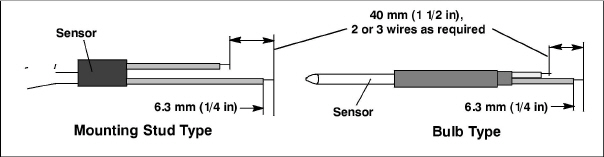
2.Cut cable. Slide the cap and grommet off a bulb type sensor and save for reuse. Do not cut the grommet.
3.Cut one wire of existing cable 40 mm (1-1/2 inches) shorter than the other wire.
4.Cut replacement sensor wires (opposite colors) back 40 mm (1-1/2 inches). See Figure 7.30.
5.Strip back insulation on all wiring 6.3 mm (1/4 inch).
6.Slide a large piece of heat shrink tubing over the cable, and place the two small pieces of heat shrink tubing, one over each wire, before adding crimp fittings as shown in Figure 7.31.
Figure 7.31 Sensor and Cable Splice
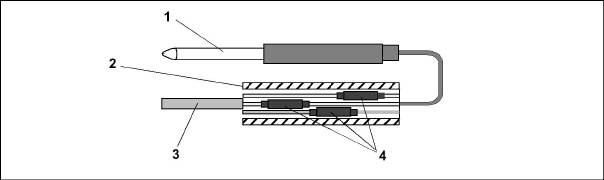
1)Sensor (typical)
2)Large Heat Shrink Tubing (1)
3)Cable
4)Heat Shrink Tubing (2 or 3 as required)
- - - - -
7.If required, slide the cap and grommet assembly onto the replacement sensor.
8.Slip crimp fittings over dressed wires (keeping wire colors together). Make sure wires are pushed into crimp fittings as far as possible and crimp with crimping tool.
9.Solder spliced wires with a 60% tin and 40% lead Rosincore solder.
10.Slide heat shrink tubing over each splice so that ends of tubing cover both ends of crimp as shown in Figure 7.30.
11.Heat tubing to shrink over splice. Make sure all seams are sealed tightly against wiring to prevent moisture seepage.
Do not allow moisture to enter wire splice area as this may affect the sensor resistance.
12.Slide large heat shrink tubing over both splices and shrink.
13.Position the sensor in unit as shown in Figure 7.31 and re-check sensor resistance.
14.Reinstall the sensor. See Section 7.22.5.
The P5 Pre-Trip test must be run to inactivate probe alarms. See Section 5.8.
7.22.5Sensor STS and SRS Re-Installation
To properly position a supply sensor, the sensor must be fully inserted into the probe holder. See Figure 7.32. Do not allow heat shrink covering to contact the probe holder. For proper placement of the sensor, be sure to position the enlarged positioning section of the sensor against the side of the mounting clamp. This positioning will give the sensor the optimum amount of exposure to the supply air stream, and will allow the controller to operate correctly.
Figure 7.32 Supply Sensor Positioning
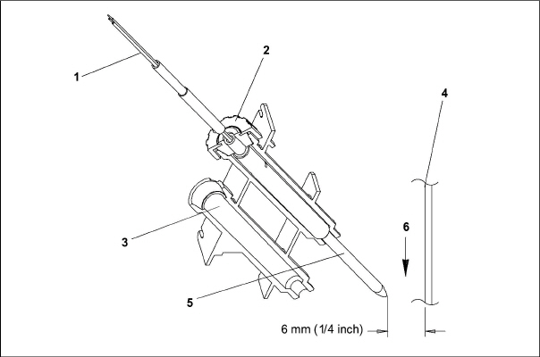
1)Sensor Wires
2)Cap and Grommet Assembly
3)Probe Holder
4)Evaporator Back Panel
5)Supply Sensor
6)Supply Air Stream
- - - - -
7.22.6Sensors RRS and RTS Re-Installation
Reinstall the return sensor as shown in Figure 7.33. For proper placement of the return sensor, be sure to position the enlarged positioning section of the sensor against the side of the mounting clamp.
Figure 7.33 Return Sensor Positioning
1)Mounting Clamp
2)Return Sensor
- - - - -
7.22.7Sensor DTS Re-Installation
The DTS sensor must be installed with the long, flat edge against the coil center tube sheet in order to accurately measure the coil temperature.
7.22.8Sensors ETS1 Re-Installation
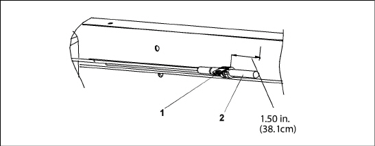
The ETS1 sensor is located in a tube holder under insulation, as shown in Figure 7.34. When the combo sensor is removed and reinstalled, it must be placed in a tube holder by applying thermal grease. Insulating material must completely cover the sensor to ensure the correct temperature is sensed.
Figure 7.34 Evaporator Temperature Sensor Positioning
7.22.9Sensor, CPDS Re-Installation
To replace the Compressor Discharge Sensor perform the following:
1.Ensure the unit is disconnected from the power source and that ST is in OFF position.
2.Remove the existing sensor. Clean all silicone sealer and dielectric compound from the sensor well. Ensure well is clean and dry. Top of compressor, where the sensor seals, must also be clean and dry.
3.Using the syringe supplied with the replacement sensor, squeeze all of the dielectric compound into the sensor well.
4.Place a bead of the silicone sealer supplied with the replacement sensor around the sensor sealing ring. Insert sensor into the well with the leads parallel to the suction fitting.
5.Reconnect sensor and run a Pre-trip to test. See Figure 7.30.
The location of the Discharge Pressure Transducer (DPT), Suction Pressure Transducer (SPT), and Flash Tank Pressure Transducer (FPT) can be found in Figure 3.3 and Figure 3.4.
Remove and replace transducers using the following procedure:
1.Remove the refrigerant charge from the unit. See Section 7.2.5.
2.Disconnect wiring from defective transducer.
When removing or installing a transducer from the unit, always use a deep well socket or box end wrench to prevent crushing of the transducer. Never use an open end wrench (see Figure 7.35). Using an open end wrench will concentrate pressure on only two sides of the transducer housing which can potentially crush the transducer.
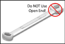
3.Using a deep well socket or box end wrench, turn the transducer assembly counterclockwise to loosen and remove the defective transducer.
4.Using a deep well socket or box end wrench, install the new transducer. The torque values for each transducer are listed below:
•SPT: 25.7-28.5 Nm (19-21 ft-lb)
•DPT and FPT: 9.5-12.2 Nm (7-8 ft-lb)
5.Reconnect the wiring to the new Transducer.
6.Evacuate and dehydrate the system. See Section 7.2.7.
7.Recharge the system. See Section 7.2.8.
8.Start the unit, verify refrigeration charge. See Section 3.6.
7.24Communications Interface Module Installation
Units that have been factory provisioned for installation of a communication interface module (CIM) have the required wiring installed. If the unit is not factory provisioned, a provision wiring kit (Carrier Transicold part number 76-00685-00) must be installed. Installation instructions are packaged with the kit. To install the module, do the following:
Installation requires wiring to the main unit circuit breaker, CB-1. Make sure the power to the unit is off and power plug disconnected before beginning installation.
1.CB-1 is connected to the power system, see wiring schematic. Ensure that the unit power is off AND that the unit power plug is disconnected.
2.Open control box and remove low voltage shield. See Figure 7.36. Open the high voltage shield.
3.If using factory provisioned wiring, remove the circuit breaker panel, with circuit breaker, from the control box. Locate, wires CB21/CIA3, CB22/CIA5 and CB23/CIA7 that have been tied back in the wire harness. Remove the protective heat shrink from the ends of the wires.
4.Refit the circuit breaker panel.
5.Fit the new CIM into the unit.
6.Attach three wires CB21/CIA3, CB22/CIA5 and CB23/CIA7 to the CIM at connection CIA.
7.Locate connectors CIA and CIB, remove plugs if required, and attach to the module.
8.Replace the low voltage shield.
Figure 7.36 Communications Interface Installation
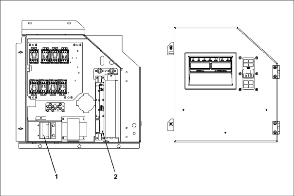
1)Circuit Breaker (CB1)
2)Communications Interface Module
- - - - -
7.25Maintenance Of Painted Surfaces
The refrigeration unit is protected by a special paint system against the corrosive atmosphere in which it normally operates. However, should the paint system be damaged, the base metal can corrode. In order to protect the refrigeration unit from the highly corrosive sea atmosphere, or if the protective paint system is scratched or damaged, clean area to bare metal using a wire brush, emery paper or equivalent cleaning method. Immediately following cleaning, apply two-part epoxy paint to the area. and allow to dry. After the first coat dries, apply a second coat.
7.26Temperature / Pressure Chart
** 87.8°F is the Critical point of CO2, Pressure 1056.2psig. Distinct liquid and vapor states do not exist.
**** 31.1°C is the Critical point of CO2, Pressure 72.82Bar. Distinct liquid and vapor states do not exist.