4.1Temperature Control Microprocessor System
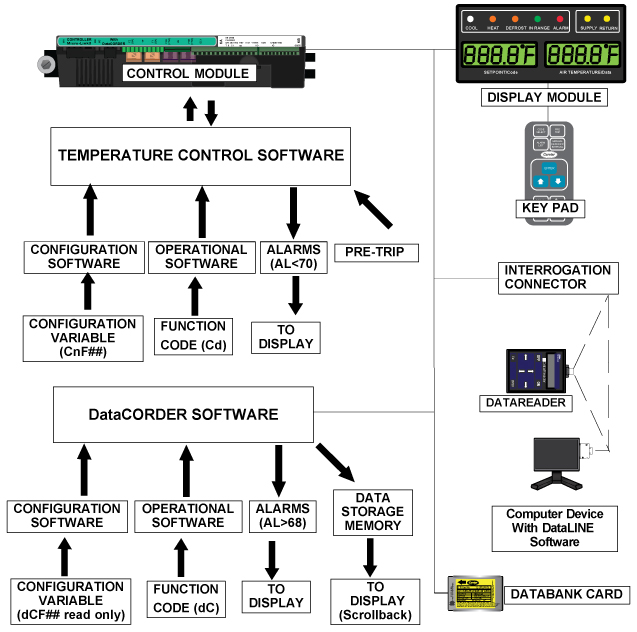
The temperature control Micro-Link 3 microprocessor system (see Figure 4.1) consists of a keypad, display module, the control module (controller) and interconnecting wiring. The controller houses the temperature control software and the DataCORDER software. The temperature control software functions to operate the unit components as required to provide the desired cargo temperature and humidity. The DataCORDER software functions to record unit operating parameters and cargo temperature parameters for future retrieval. Coverage of the temperature control software begins with Section 4.2. Coverage of the DataCORDER software is provided in Section 4.7.
Figure 4.1 Temperature Control System
4.1.1Display Module and Keypad
The display module and keypad serve to provide user access and readouts for both of the controller functions, temperature control and DataCORDER. The functions are accessed by keypad selections and viewed on the display module.
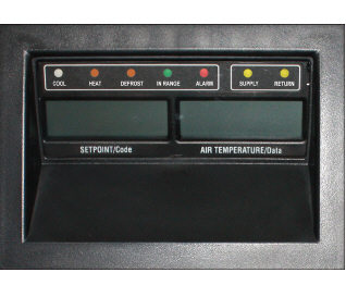
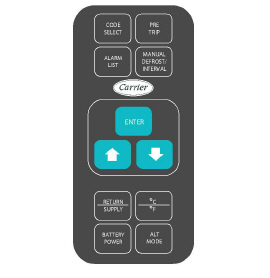
The display module (see Figure 4.2) consists of two 5-digit displays and seven indicator lights. Descriptions of the indicator lights are provided in Figure 4–1. The keypad (see Figure 4.3) consists of eleven push button switches that act as the user’s interface with the controller. Description of the switch functions are provided in Figure 4–2.
Do not remove wire harnesses from controller modules unless you are grounded to the unit frame with a static safe wrist strap.
Unplug all controller module wire harness connectors before performing arc welding on any part of the container.
Do not attempt to use an ML2i PC card in an ML3 equipped unit. The PC cards are physically different and will result in damage to the controller.
Do not attempt to service the controller modules. Breaking the seal will void the warranty.
The Micro-Link 3 controller is a dual module microprocessor as shown in Figure 4.4. It is fitted with test points, harness connectors and a software card programming port.
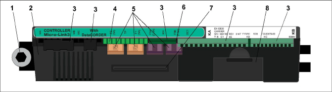
2)Micro-Link 3 Control/DataCORDER Module
6)Control Circuit Power Connection
8)Battery Pack (Standard Location)
- - - - -
The controller software is a custom designed program that is subdivided into configuration software and operational software. The controller software performs the following functions:
•Control supply or return air temperature to required limits, provide modulated refrigeration operation, economized operation, unloaded operation, electric heat control and defrost. Defrost is performed to clear buildup of frost and ice in order to ensure proper air flow across the evaporator coil.
•Provide default independent readouts of setpoint and supply or return air temperatures.
•Provide ability to read and (if applicable) modify the configuration software variables (CnF, see Table 4–6), operating software function codes (Cd, see Table 4–7) and alarm code (AL, see Table 4–8) indications.
•Provide a Pre-trip step by step checkout of refrigeration unit performance including: proper component operation, electronic and refrigeration control operation, heater operation, probe calibration, pressure limiting and current limiting settings. See Section 4.12.
•Provide battery-powered ability to access or change selected codes and setpoint without AC power connected.
•Provide the ability to reprogram the software through the use of a memory card.
4.2.1Configuration Variables (CnF)
The configuration software is a variable listing of the components available for use by the operational software. This software is factory installed in accordance with the equipment fitted and options listed on the original purchase order. Changes to the configuration software are required only when a new controller has been installed or a physical change has been made to the unit such as the addition or removal of an option. A configuration variable list is provided in Table 4–6. Change to the factory-installed configuration software is achieved via a configuration card or by communications.
4.2.2Operational Software (Cd Function Codes)
The operational software is the actual operation programming of the controller which activates or deactivates components in accordance with current unit operating conditions and operator selected modes of operation.
The programming is divided into function codes. Some of the codes are read only while the remaining codes may be user configured. The value of the user configurable codes can be assigned in accordance with user desired mode of operation. A list of the function codes is provided in Table 4–7.
To access the function codes, perform the following:
1.Press the CODE SELECT key, then press an Arrow key until the left window displays the desired code.
2.The right window will display the value of this code for five seconds before returning to normal display mode.
3.If a longer time is desired, press the ENTER key to extend the time to five minutes.
4.3Controller Sequence And Modes Of Operation
Compressor Contactor is always ON. The compressor speed is determined by specific operating conditions then the Micro will send commands to the Variable Frequency Drive.
General operation sequences for cooling, heating and defrost are provided in the following sub-paragraphs. Schematic representation of controller action is provided in Figure 4.5.
The operational software responds to various inputs. These inputs come from the temperature and pressure sensors, the temperature setpoint, the settings of the configuration variables and the function code assignments. The action taken by the operational software will change if any one of the inputs change. Overall interaction of the inputs is described as a “mode” of operation. The modes of operation include perishable (chill) mode and frozen mode. Descriptions of the controller interaction and modes of operation are provided in the following sub paragraphs.
At start up, the controller logic checks for proper phase sequencing and compressor rotation. If incorrect sequencing is causing the compressor and three-phase evaporator and condenser fan motors to rotate in the wrong direction, the controller will energize or de-energize relay TCP as required (see Figure 8.2). Relay TCP will switch its contacts, energizing or de-energizing relays PA and PB. Relay PA is wired to energize the circuits on L1, L2 and L3. Relay PB is wired to energize the circuits on L3, L2, and L1, thus providing reverse rotation.
Upon start up, valves are opened to allow for equalization of system pressures. As the start up procedure transitions to control mode, the evaporator and gas cooler fans cycle on, the Economizer Solenoid Valve (ESV) will energize, and the compressor and Variable Frequency Drive (VFD) ramp up.
During normal operation of the refrigeration system, system pressures and suction superheat are controlled by predetermined algorithms within the software. Temperature control is maintained by VFD speed and cycling of the gas cooler fan (high / low / off).
4.3.2Perishable Mode Temperature Control
In the Standard Perishable Mode of Operation, the evaporator fan motors run in high speed.
In Perishable Mode, the yellow SUPPLY indicator light is illuminated on the display module, the default reading on the display window reflects the Supply Temperature Sensor (STS) reading, and the controller maintains supply air temperature to setpoint. When supply air temperature reaches the In-Range Tolerance (Cd30), the green IN RANGE light will energize.
The unit will be in Perishable Mode whenever setpoint is higher than -10°C (+14°F) [-5°C (+23°F) depends upon the CnF26 (Heat Lockout Change Option) setting].
When operating in Perishable Mode, the microprocessor continuously controls the system in an effort to maintain supply air temperature within the perishable limit of +/-0.25°C. In Perishable Mode, capacity reduction controls may be implemented to ensure that the refrigeration system (compressor) does not shut down. Capacity reduction measures include modulation of the Gas Cooler Fan speed (high, low, off), closing of the ESV, opening of the USV, and VFD speed reduction. After all of the capacity reduction measures have been implemented, if the temperature continues to fall below the control limit, the unit will turn off the refrigeration circuit (compressor) and run with evaporator fans only. If the temperature continues to fall below setpoint, the unit will engage the heaters to maintain temperature within the control band.
4.3.3Perishable Mode Cooling - Sequence of Operation
a.When the supply air temperature is above setpoint and decreasing, the unit will energize the compressor contactor (CH), gas cooler fan motor / (GF), Economizer Solenoid Valve (ESV), evaporator fan motors (EM) / high speed contactor (EF), and the white COOL light is energized. If pressure limiting is not active, the controller will close contacts TS to open the Economizer Solenoid Valve (ESV), placing the unit in economized operation.
b.When the supply air temperature decreases to a predetermined tolerance (Cd30) above setpoint, the green IN RANGE light is energized.
c.As the supply air temperature continues to fall, VFD speed reduction will reduce compressor speed, and the ESV will be closed, taking the system out of economized operation. As supply air temperature approaches setpoint, the controller will cycle the gas cooler fan on/off.
d.As the controller continuously monitors supply air temperature, calculations are performed to determine temperature drift from setpoint over time. If the calculations determine that cooling is no longer required, the compressor will cycle off, and the white COOL light is de-energized.
e.Evaporator fan motors will continue to operate in order to circulate air throughout the container. The green IN RANGE light will remain energized as long as the supply air temperature is maintained within tolerance of setpoint.
Figure 4.5 Controller Operation - Perishable Mode
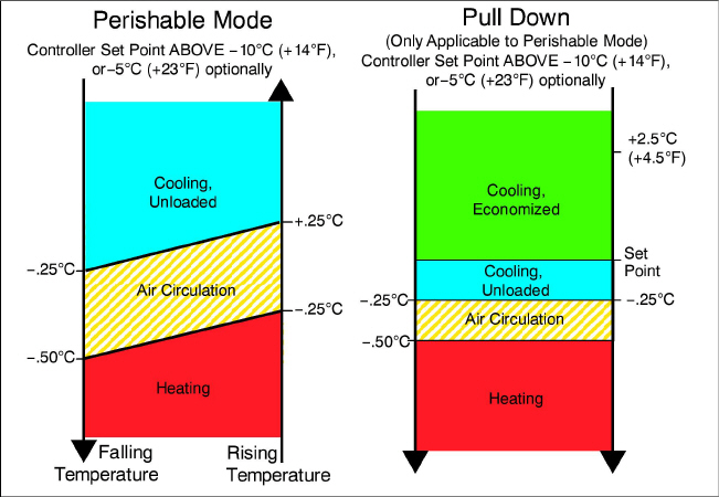
4.3.4Perishable Mode Heating - Sequence of Operation
a.If the supply air temperature falls to 0.5°C (0.9°F) below setpoint, the system will enter Perishable Mode Heating (see Figure 4.5). The controller will close contacts TH to allow power to flow through the Heat Termination Thermostat (HTT) to energize the Heater Contactor (HR). The orange HEAT light will be energized, and the evaporator fans will continue to operate in order to circulate heated air throughout the container.
b.When the supply temperature rises to 0.25°C (0.45°F) below setpoint, contacts TH open to de-energize the heaters. The orange HEAT light will be de-energized, and the evaporator fans continue to operate in order to circulate air throughout the container.
c.If supply rises to 54°C (130°F), the Heat Termination Thermostat (HTT) will open and de-energize HR. HTT is mounted to the evaporator center tube sheet.
4.3.5Perishable Mode Dehumidification
Perishable Mode Dehumidification is activated to reduce humidity levels inside the container. The dehumidification setpoint is entered using function code Cd33, Humidity Setpoint. When dehumidification is active, the controller will energize the Heater Contactor (HR), and the yellow SUPPLY light will flash ON and OFF every second. In order for dehumidification to be activated, the following conditions must be satisfied:
•The Humidity Sensor (HS) reading is above the Humidity Setpoint, Cd33.
•The unit is in Perishable Steady State mode and supply air temperature is less than 0.25°C (0.45°F) above setpoint.
•The Heater Debounce Timer has timed out (five minutes).
•The High Pressure Switch (HPS) is not open.
•The Heat Termination Thermostat (HTT) is closed.
If the above conditions are true, the evaporator fans will switch from high speed to low speed; evaporator fan speed will switch every hour thereafter as long as all conditions are maintained. If any condition except item (1) becomes false OR if the relative humidity sensed is 2% below the humidity setpoint, the high speed evaporator fans will be energized.
During dehumidification, power is applied to the heaters; this added heat causes the controller to force the evaporator temperature down in order to compensate for the increased load. The low coil temperature chills the return air (below dew point), causing excess moisture to condensate on the coil. The water that is collected from the coil is drained out of the system through the drain pan. The air is then reheated to setpoint, and the dehumidified supply air is sent back to the container.
When the relative humidity sensed is 2% below the humidity setpoint, the controller will de-energize the heat relay, however the controller will continue to cycle heating, when required, to maintain relative humidity below the selected setpoint. If the dehumidification is terminated by a condition other than the sensed humidity level, e.g., an out-of-range or compressor shutdown condition, the Heater Contactor (HR) is de-energized immediately.
To prevent rapid cycling and consequent Heater Contactor (HR) wear, two timers are activated during dehumidification mode:
1.Heater Debounce Timer (five minutes) - The Heater Debounce Timer is started whenever the Heater Contactor (HR) status is changed. The HR remains energized (or de-energized) for at least five minutes even if the setpoint criteria are satisfied.
2.Out-of-Range Timer (five minutes) - The out-of-range timer is started to maintain heater operation for dehumidification during a temporary temperature out-of-range condition. If the supply air temperature remains out of range for more than five minutes, the heaters will be de-energized to allow the system to recover. The out-of-range timer starts as soon as the temperature exceeds the in-range tolerance value set by function code Cd30.
4.3.6Perishable Dehumidification - Bulb Mode
Bulb mode is an extension of dehumidification which allows changes to the evaporator fan speed and/or defrost termination setpoints.
Bulb mode is active when Cd35 is set to “Bulb.” Once bulb mode is activated, the user may then change dehumidification evaporator fan operation from the default to constant low or constant high speed. This is done by toggling Cd36 from its default of “alt” to “Lo” or “Hi” as desired. If low speed evaporator fan operation is selected, this gives the user the additional capability of selecting dehumidification setpoints from 60 to 95%.
In addition, if bulb mode is active, Cd37 may be set to override the previous defrost termination thermostat (DTT) settings. The temperature at which the DTT will be considered “open” may be changed [in 0.1°C (0.2°F) increments] to any value between 25.6°C (78°F) and 4°C (39.2°F). The temperature at which the DTT is considered closed for interval timer start or demand defrost is 10°C for “open” values from 25.6°C (78°F) down to a 10°C setting. For “open” values lower than 10°C, the “closed” values will decrease to the same value as the “open” setting. Bulb mode is terminated when:
1.Bulb mode code Cd35 is set to “Nor.”
2.Dehumidification code Cd33 is set to “Off.”
3.The user changes the setpoint to one that is in the frozen range.
When bulb mode is disabled by any of the above conditions, evaporator fan operation for dehumidification reverts to “alt” and the DTS termination setting resets to the value determined by CnF41.
4.3.7Frozen Mode Temperature Control
When configuration variable CnF26 (Heat Lockout Change Option) is set to -10C, Frozen Mode is active with setpoints at or below -10°C (+14°F). When CnF26 is set to -5°C, Frozen Mode is active at or below -5°C (+23°F).
In Frozen Mode, the yellow RETURN indicator light is energized, the default reading on the display window reflects the Return Temperature Sensor (RTS) reading, and the controller maintains return air temperature to setpoint. When return air temperature reaches the In-Range Tolerance (Cd30) the green IN RANGE light will energize.
When operating in Frozen Mode additional controls are applied to the Evaporator Fans and VFD Speed. If temperature is above the setpoint plus the control band, the VFD will operate at maximum allowable speed. As the control temperature approaches setpoint, the compressor speed will be reduced to maintain temperature to within -0.2°C (0.36°F) of setpoint. If the temperature should continue to fall, the system will turn off the refrigeration circuit and operate with evaporator fans at low speed only.
Figure 4.6 Controller Operation - Frozen Mode
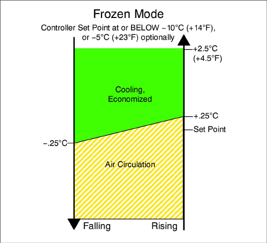
4.3.8Frozen Mode Cooling - Sequence of Operation
Unit will be in Frozen Mode whenever setpoint is at or lower than -10°C (+14°F) or -5°C (+23°F) depending upon the CnF26 (Heat Lockout Change Option) setting.
a.When the return air temperature is above setpoint and decreasing, the unit will energize the compressor contactor (CH), the gas cooler fan motor (GM), the gas cooler high speed contactor (GF), the evaporator fan motors (EM), the evaporator low speed contactor (ES), and the Economizer Solenoid Valve (ESV). The white COOL light is also energized.
b.When return air temperature decreases to a predetermined tolerance above setpoint, the green IN RANGE light is energized.
c.When the return air temperature decreases to a predetermined point below setpoint, the controller will set the VFD to 0%, and de-energize the gas cooler fan motor (GM), the gas cooler high speed contactor (GF), and Economizer Solenoid Valve (ESV). The white COOL light is also de-energized.
d.The evaporator fan motors continue to run in low speed to circulate air throughout the container. The green IN RANGE light remains energized as long as the return air is within tolerance of setpoint.
e.If return air temperature drops to 10°C (18°F) or more below setpoint, the evaporator high speed contactor (EF) energizes to increase fans to high speed to initiate Frozen Mode “heating”.
f.When the return air temperature increases to 0.25°C (0.45°F) above setpoint and three minutes have elapsed, the controller will return to the frozen cooling mode.
Defrost is initiated to remove ice buildup from the evaporator coil which can obstruct air flow and reduce the cooling capacity of the unit. The defrost cycle may consist of up to three distinct operations depending upon the reason for the defrost or model number configuration. The first is de-icing of the coil, the second is defrost due to a probe check cycle and the third is a snap freeze process based on the unit model configuration.
•De-icing the coil consists of removing power to the cooling components (compressor, evaporator fans, and condenser fan), closing the EEV, and turning on the heaters, which are located below the evaporator coil. During normal operation, de-icing will continue until temperatures indicate that the ice on the coil has been removed, proper air flow has been restored, and the unit is ready to control temperature efficiently.
•If defrost was initiated by the probe check logic, then the Probe Check is carried out after the completion of the defrost cycle. A Probe Check is initiated only when there is an inaccuracy between the controller temperature sensors.
•Snap Freeze allows the system to cool for a period of time after de-icing, with the evaporator fans turned off and is only carried out if configured by model number. Snap-Freeze allows for the removal of latent de-icing heat from the evaporator coils, and freezes any remaining moisture that might otherwise be blown into the container.
For more information on Probe Check, see Section 5.8.
Initiation of defrost is dependent on the state of the Defrost Temperature Sensor (DTS). When the DTS senses a temperature less than 10°C (50°F), the defrost options become active and the timer is engaged for the initiation of the defrost cycle. The defrost time accumulates when the compressor is running. In the perishable mode, this is the same as real time as the compressor in general runs continuously. In frozen mode, the actual time necessary to count down to the next defrost will exceed the defrost interval depending on the compressor duty-cycle.
When the defrost mode is in the active state, defrost can be initiated when any one of the following additional conditions become true:
1.Manually: Press and hold the MANUAL DEFROST / INTERVAL key for 5 seconds.
2.Timer: The Defrost Interval Timer reaches the user selectable Interval. The user-selected intervals are 3, 6, 9, 12, 24 Hours, Off, AUTO, or Pulse; factory default is AUTO. Refer to Defrost Interval setting on the Trip Settings screen.
a.Automatic defrost starts with an initial defrost at three hours and then adjusts the interval to the next defrost based on the accumulation of ice on the evaporator coil. Following a start-up or after termination of defrost, the time will not begin counting down until the DTS reading falls below 10°C (50°F). If the reading of DTS rises above termination setting any time during the timer count down, the interval is reset and the countdown starts over. The Auto defrost time is reset to three hours start time after every PTI initiation or trip start interval.
b.Fan Pulsing Logic is used to help prevent ice formation in the drain gutter and drain cup and ice buildup in supply air channel by using the evaporator fans to blow the warm air onto these areas during unit defrost. When cooling at lower setpoints, evaporator fan pulsing can be used during Defrost / De-ice when the “Pulse” option is selected for the Defrost Interval setting on the Trip Settings screen. When enabled, evaporator fan pulsing will occur based on the unit temperature setpoint and the Evap Fan Pulsing Temp setting on the Trip Settings screen. QUEST II also pulses the evaporator fans during Defrost/De-ice within a narrow perishable setpoint range. The logic for each evaporator fan pulsing feature is described below.
c.After a new Defrost Interval is selected, the previously selected Interval is used until the next defrost termination, the next time the DTS contacts are OPEN, or the next time power to the control is interrupted. If the previous value or the new value is “OFF”, the newly selected value will be used immediately.
3.Probe Check: If defrost is initiated due to Probe Check immediately following the defrost cycle the evaporation fans are started and run for eight minutes to stabilize the temperature throughout the container. A probe check comparison is carried out at the end of the eight minute period if any sensor is found out of calibration. At this time its alarm set is no longer used for control/reorder purposes.
4.Delta T Logic: If the difference between return and supply air temperature (Delta T) becomes too great indicating possible reduced airflow over the evaporator coil caused by ice buildup requiring a defrost.
a.In Perishable Pull Down - Delta T increases to greater than 12°C, and 90 minutes of compressor run time have been recorded.
b.In Perishable Steady State - A baseline Delta T is recorded following the first defrost cycle after steady state conditions are reached, (the unit is cooling, and the evaporator fans and heaters must remain in a stable state for a period of five minutes). Defrost will be initiated if Delta T increases to greater than 4°C above the baseline, and 90 minutes of compressor run time have been recorded.
c.In Frozen Mode - Defrost will be initiated if Delta T increases to greater than 16°C and 90 minutes of compressor run time have been recorded.
When defrost is initiated, the controller closes the EEV, opens contacts TC, TN and TE (or TV) to de-energize the compressor, condenser fan and evaporator fans.
The controller then closes contacts TH to supply power to the heaters. The orange DEFROST light and heat light are illuminated and the COOL light is also de-energized.
The EEV and DUV are independently operated by the microprocessor. Complete schematics and legends are located in Section 9.
Defrost will terminate when the DTS reading rises above one of two model number configurable options selection, either an upper setting of 25.6°C (78°F) which is default or lower setting of 18°C (64°F). When the DTS reading rises to the configured setting, the de-icing operation is terminated.
4.3.11Defrost Related Settings
DTS Failure
When the return air temperature falls to 7°C (45°F), the controller ensures that the defrost temperature sensor (DTS) reading has dropped to 10°C or below. If it has not, it indicates a failed DTS. A DTS failure alarm is triggered and the defrost mode is operated by the Return Temperature Sensor (RTS). Defrost will terminate after 1 hour.
If the DTS fails to reach is termination setting, the defrost terminate after 2 hours of operation.
Defrost Timer
If CnF23 is configured to “SAv” (save), then the value of the defrost interval timer will be saved at power down and restored at power up. This option prevents short power interruptions from resetting an almost expired defrost interval, and possibly delaying a needed defrost cycle. If the save option is not selected the defrost timer will re-initiate and begin recounting.
If CnF11 is model number configured to OFF the operator will be allowed to choose “OFF” as a defrost interval option.
If CnF64 is configured in the operator will be allowed to choose “PuLS” as a defrost interval option. For units operating with “PuLS” selected, defrost interval is determined by the unit temperature setpoint and the Evap Fan Pulsing Temp setting on the Trip Settings screen. When the unit temperature setpoint is equal to or less than the Evaporator Fan Pulsing Temperature Setting, the defrost interval is set to 6 hours. Otherwise, the defrost interval is determined using the Automatic Defrost Interval Determination logic. In either case, “PuLS” remains displayed in this function select code.
If any Auto Pretrip sequence is initiated, the Defrost Interval setting will be set to “AUTO” unless CnF49 (OEM Reset) is set to “Custom” AND CnF64 (Evaporator Fan Pulsing Logic) configuration variable is set to IN, in which case the Defrost Interval setting on the Trip Settings screen will be set to “Pulse”.
If defrost does not terminate correctly and temperature reaches the setpoint of the Heat Termination Thermostat (HTT) 54°C (130°F), the HTT will open to de-energize the heaters (AL059 & AL060). If the HTT does not open and termination does not occur within two hours, the controller will terminate defrost. AL060 will be activated to inform of a possible DTS failure.
4.4Protection Modes Of Operation
Opening of an evaporator fan internal protector will shut down the unit.
Function code Cd29 may be operator set to select action the controller will take upon system failure. The factory default is full system shutdown. See Table 4–7.
Function codes Cd31(Stagger Start, Offset Time) and Cd32 (Current Limit) may be operator set to control the start up sequence of multiple units and operating current draw. The factory default allows on demand starting (no delay) of units and normal current draw. See Table 4–7.
4.4.4Compressor High Temperature, Low Pressure Protection
The controller monitors the temperatures and pressures within the system. If pressure or temperatures rise above or below the allowed limit, the compressor will be cycled off and all system valves will be moved to preset positions. The gas cooler fan will continue to run for 30 seconds. After 3 minutes the temperature and pressures will be checked, if they have returned to allowable values the unit will restart according to normal control algorithm. The controller will continue to monitor these limits. If they continue to trip, the controller will adjust the off time in order to allow for unit stabilization.
4.4.5Compressor Internal Protector (IP)
The reciprocating compressor internal protector (IP) is a thermal switch that is integrated into the 24 volt circuit. When the internal temperature of the compressor gets too high, the thermal switch (IP), which is embedded in the compressor motor windings, opens. This causes a break in the 24 volt circuit which de-energizes the compressor contactor (CH) and removes power to the compressor. When the microprocessor senses the open circuit AL24 is triggered on.
Once the compressor internal temperature falls below the setpoint, the thermal switch (IP) closes and restores the 24 volt circuit. This closes the compressor contactor (CH), restores power to the compressor, and AL24 is triggered off.
Alarm display is an independent controller software function. If an operating parameter is outside of expected range or a component does not return the correct signals back to the controller, an alarm is generated. A listing of the alarms is provided in Table 4–8.
The alarm philosophy balances the protection of the refrigeration unit and that of the refrigerated cargo. The action taken when an error is detected always considers the survival of the cargo. Rechecks are made to confirm that an error actually exists.
Some alarms requiring compressor shutdown have time delays before and after to try to keep the compressor on line. An example is alarm code “LO,” (low main voltage), when a voltage drop of over 25% occurs, an indication is given on the display, but the unit will continue to run.
When an Alarm Occurs:
•The red ALARM light will energize for critical alarm code numbers 20, 21, 22, 23, 24, 25, 26, and 27.
•If a detectable problem exists, its alarm code will be alternately displayed with the setpoint on the left display.
•The user should scroll through the alarm list to determine what alarms exist or have existed. Alarms must be diagnosed and corrected before the alarm list can be cleared.
1.While in the Default Display mode, press the ALARM LIST key. This accesses the Alarm List Display Mode, which displays any alarms archived in the alarm queue.
2.The alarm queue stores up to 16 alarms in the sequence in which they occurred. The user may scroll through the list by pressing an Arrow key.
3.The left display will show “AL##,” where ## is the alarm number sequentially in the queue.
4.The right display will show the actual alarm code. “AA##” will display for an active alarm, where “##” is the alarm code. Or “IA##” will display for an inactive alarm, see Table 4–8.
5.“END” is displayed to indicate the end of the alarm list if any alarms are active.
6.“CLEAr” is displayed if all alarms are inactive. The alarm queue may then be cleared by pressing the ENTER key. The alarm list will clear and “-----” will be displayed.
AL26 is active when all of the sensors are not responding. Check the connector at the back of the controller; if it is loose or unplugged, reconnect it, then run a Pre-trip test P5 to clear AL26.
Pre-trip Diagnostics is an independent mode that suspends normal Control Mode activities to verify system functionality by running a series of individual tests. The tests can be run in Auto Mode, which automatically performs a pre programmed sequence of tests, or Manual Mode, which allows the operator to select and run any of the tests individually.
A description of each individual Pre-trip test can be found in Section 4.12. Detailed operating instructions are provided in Section 5.7.
Pre-trip diagnostics should not be performed with critical temperature cargoes in the container.
When PRE-TRIP key is pressed, economy, dehumidification and bulb mode will be deactivated. At the completion of Pre-trip activity, economy, dehumidification and bulb mode must be reactivated.
Pre-trip testing is initiated by pressing the PRE-TRIP key. This causes “SeLCt PrtrP” to be displayed for five seconds or until an Arrow key is pressed. Pressing an Arrow key opens the test selection menu. Scroll through the menu with the Arrow keys and then press the ENTER key to start the indicated test sequence or individual test.
Selecting “P rSLts” and pressing the ENTER key displays the results of all Pre-trip sub-tests. The results are displayed as “PASS” or “FAIL” for all tests run to completion since power on, and displayed as “-----” for tests not run.
During selection mode, failure to press either an Arrow key or ENTER key for 5 seconds will return the system to its default display, and normal operating mode.
There are two Auto Mode test sequences:
•Short Pre-trip Sequence tests most functions, sensors, and system components. The Short Sequence does not test the high pressure switch, heater performance, or cooling performance, due to their duration.
•Long Pre-trip Sequence includes all of the Short Sequence Tests, as well as tests for the high pressure switch, heater performance, and cooling performance. The Long Sequence is only available if enabled by configuration. Units configured for the Long Sequence can run either the Short Sequence or the Long Sequence.
Manual Mode allows individual Pre-trip tests to be run one at a time, giving operators the ability to test individual system components.
Pre-trip diagnostics may also be initiated via communication; however individual Manual Mode tests can only be initiated at the keypad.
While a Pre-trip test is running, PX-X will be displayed on the left, where the X’s indicate the test number and sub-test. The right display will show a countdown timer in minutes and seconds. During the Long Sequence, various relevant temperature and pressure information will replace the countdown timer on the right display.
4.6.1Auto Test Operation from Keypad
When a Pre-trip auto test is initiated, the system executes a series of individual tests without any need for operator interface (except P0-0 where the proper functioning of the display must be observed). Each individual Pre-trip test varies in length, depending on the component being tested.
When the auto or auto1 testing is allowed to run to completion, without operator interruption, the system will exit Pre-trip mode and return to normal control operation. When the auto2 or auto3 test series is selected, and runs uninterrupted to successful completion, the unit will turn off all machinery, display either “AUtO2” “end” or “AUtO3” “end”, and wait for an ENTER key press before returning to normal control operation.
If an individual test fails, the test will be repeated once automatically from the beginning of the current Pre-trip test (not sub-test). An exception to this is with Long Sequence sub-tests P8-0 and P10-0. If either one of these sub-tests fails they will not be automatically repeated; failure of sub-tests P8-1, P8-2, P10-1 and P10-2 will cause automatic repeat. Repeated failure of a test will cause “FAIL” to be shown on the right display, with the corresponding test number to the left, and the SUPPLY and RETURN LED’s will be flashed alternately. Pressing the Down Arrow key will repeat the test, pressing the Up Arrow key will skip to the next test. The system will wait indefinitely for operator input. Holding the PRE-TRIP key will terminate Pre-trip mode operation. This is true for both auto2 and auto3 tests (auto3 does not include P10).
Individually selected Pre-trip tests, other than the LED / Display test (P0-0), allow the operator to verify the functionality of an individual component. At the conclusion of the selected test, “PASS” or “FAIL” will be displayed. Upon failure, the SUPPLY and RETURN LED’s will flash on alternately. This message will remain displayed for up to three minutes, in which time the operator may select another test. If three minutes expires, the system will terminate Pre-trip and return to control mode operation. Following any individually selected Pre-trip test, all outputs will be de-energized.
4.6.3Auto Test Operation from Serial Communications
Pre-trip may also be initiated via communications. The operation is the same as for the Auto Test mode except that if a test fails, Pre-trip mode will automatically terminate. When initiated via communications, a test may not be interrupted with an Arrow key, but Pre-trip mode can be terminated with the PRE-TRIP key.
A Pre-trip test can be terminated by pressing and holding the PRE-TRIP key for 1 to 2 seconds. The system will then resume normal operation. Any Pre-trip test may be interrupted by pressing the Up Arrow key. This will return the operator to the test selection mode described above, and all machinery outputs will be de-energized. Pre-trip may also be terminated via communications.
The system may be configured to send Pre-trip test results along with embedded test data points to the DataCORDER at the end of Pre-trip test. If not configured for data points, only results will be reported to the DataCORDER.
At the end of a Pre-trip test, the message “P rSLts” (Pre-trip results) will be displayed. Pressing the ENTER key will allow the user to see the results for all sub-tests. The results will be displayed as “PASS” or “FAIL” for all the Pre-trip tests run to completion.
Carrier Transicold “DataCORDER” software is integrated into the controller and serves to eliminate the temperature recorder and paper chart. DataCORDER functions may be accessed by keypad selections and viewed on the display module. The unit is also fitted with interrogation connections (see Figure 4.1) which may be used with the Carrier Transicold Data Reader to download data. A computer with Carrier Transicold DataLINE software may also be used to download data and configure settings. The DataCORDER consists of:
Configuration Software
Operational Software
Data Storage Memory
Real Time Clock (with internal battery backup)
Six Thermistor Inputs
Interrogation Connections
Power Supply (battery pack)
The DataCORDER performs the following functions:
a.Logs data at 15, 30, 60 or 120 minute intervals and stores two years of data (based on one hour interval).
b.Records and displays alarms on the display module.
c.Records results of Pre-trip testing.
d.Records DataCORDER and temperature control software generated data and events as follows:
Container ID Change
Software Upgrades
Alarm Activity
Battery Low (battery pack)
Data Retrieval
Defrost Start and End
Dehumidification Start and End
Power Loss (with and without battery pack)
Power Up (with and without battery pack)
Remote Probe Temperatures in the Container (USDA
Cold treatment and Cargo probe recording)
Return Air Temperature
Set Point Change
Supply Air Temperature
Real Time Clock Battery (internal) Replacement
Real Time Clock Modification
Trip Start
ISO Trip Header (When entered via
Interrogation program)
Economy Mode Start and End
“Auto 1/Auto 2/Auto 3” Pre-trip Start and End
Bulb Mode Start
Bulb Mode Changes
Bulb Mode End
USDA Trip Comment
Humidification Start and End
USDA Probe Calibration
Fresh Air Vent Position
DataCORDER Software is subdivided into Operational Software, Configurations, and the Data Memory.
Operational Software
The Operational Software reads and records inputs from the operational components. How the component information is recorded and stored is determined the DataCORDER configurations. The values of these components can be viewed through the DataCORDER function codes. To access the function codes, do the following:
1.Press the ALT. MODE and CODE SELECT keys.
2.Press an Arrow key until the left window displays the desired code number. The right window will display the value of this item for five seconds before returning to the normal display mode.
3.If a longer display time is desired, press the ENTER key to extend the display time to five minutes.
Configurations
The recording and alarm functions of the DataCORDER based on the configurations. Reprogramming to the factory installed configuration is achieved via a configuration card. Changes to the unit DataCORDER configuration may be made using the DataLINE interrogation software. A listing of the configuration variables is provided in Table 4–3. Descriptions of DataCORDER operation for each variable setting are provided in the following paragraphs.
4.7.3Sensor Configuration (dCF02)
Two modes of operation may be configured, the Standard Mode and the Generic Mode.
In Standard Mode, the user may configure the DataCORDER to record data using one of seven standard configurations. The seven standard configuration variables, with their descriptions, are listed in Table 4–3. The inputs of the six thermistors (supply, return, USDA #1, #2, #3 and cargo probe) and the Humidity Sensor (HS) input will be generated by the DataCORDER.
The DataCORDER software uses the Supply and Return Recorder Sensors (SRS, RRS). The temperature control software uses the Supply and Return Temperature Sensors (STS, RTS).
Generic Mode allows user selection of the network data points to be recorded. The user may select up to a total of eight data points for recording. A list of data points available for recording follows. Changing the configuration to generic and selecting which data points to record may be done using the Carrier Transicold Data Retrieval Program.
1.Control mode
2.Control temperature
3.Frequency
4.Humidity
5.Phase A current
6.Phase B current
7.Phase C current
8.Main voltage
9.Evaporator Expansion Valve percentage
10.Discrete outputs (Bit mapped - require special handling if used)
11.Discrete inputs (Bit mapped - require special handling if used)
12.Ambient Temperature Sensor (AMBS)
13.Evaporator Temperature Sensor (ETS)
14.Compressor Discharge Sensor (CPDS)
15.Return Temperature Sensor (RTS)
16.Supply Temperature Sensor (STS)
17.Defrost Temperature Sensor (DTS)
18.Discharge Pressure Transducer (DPT)
19.Suction Pressure Transducer (SPT)
20.Flash Tank Pressure Transducer (FPT)
21.Vent Position Sensor (VPS)
The user may select four different time intervals between data recordings. Data is logged at exact intervals in accordance with the real time clock. The clock is factory set at Greenwich Mean Time (GMT).
4.7.5Thermistor Format (dCF04)
The user may configure the format in which thermistor readings are recorded. The short resolution is a 1 byte format and the long resolution is a 2 byte format. The short requires less memory and records temperature with variable resolutions depending on temperature range. The long records temperature in 0.01°C (0.02°F) steps for the entire range.
4.7.6Sampling Type (dCF05 & dCF06)
Three types of data sampling are available: average, snapshot and USDA. When configured to average, the average of readings taken every minute over the recording period is recorded. When configured to snapshot, the sensor reading at the log interval time is recorded. When USDA is configured, the supply and return temperature readings are averaged and the three USDA probe readings are snapshot.
4.7.7Alarm Configuration (dCF07 - dCF10)
The USDA and cargo probe alarms may be configured to OFF, ON or AUTO.
If a probe alarm is configured to OFF, the alarm for this probe is always disabled.
If a probe alarm is configured to ON, the associated alarm is always enabled.
If the probes are configured to AUTO, they act as a group. This function is designed to assist users who keep their DataCORDER configured for USDA recording, but do not install the probes for every trip. If all the probes are disconnected, no alarms are activated. As soon as one of the probes is installed, all of the alarms are enabled and the remaining probes that are not installed will give active alarm indications.
The DataCORDER may be powered up in any one of four ways:
a.Normal AC power: The DataCORDER is powered up when the unit is turned on via the stop-start switch.
b.Controller DC battery pack power: If a battery pack is installed, the DataCORDER will power up for communication when an interrogation cable is plugged into an interrogation receptacle.
c.External DC battery pack power: A 12 volt battery pack may also be plugged into the back of the interrogation cable, which is then plugged into an interrogation port. No controller battery pack is required with this method.
d.Real Time Clock demand: If the DataCORDER is equipped with a charged battery pack and AC power is not present, the DataCORDER will power up when the real time clock indicates that a data recording should take place. When the DataCORDER is finished recording, it will power down.
During DataCORDER power-up, while using battery-pack power, the controller will perform a hardware voltage check on the battery. If the hardware check passes, the controller will energize and perform a software battery voltage check before DataCORDER logging. If either test fails, the real time clock battery power-up will be disabled until the next AC power cycle. Further DataCORDER temperature logging will be prohibited until that time.
An alarm will be generated when the battery voltage transitions from good to bad indicating that the battery pack needs recharging. If the alarm condition persists for more than 24 hours on continuous AC power, the battery pack needs replacement.
The DataCORDER will record the initiation of a Pre-trip test (see Section 4.6) and the results of each of the tests included in Pre-trip. The data is time-stamped and may be extracted via the Data Retrieval program. See Table 4–10 for a description of the data stored in the DataCORDER for each corresponding Pre-trip test.
4.7.10DataCORDER Communications
Data retrieval from the DataCORDER can be accomplished by using one of the following: DataLINE or a communications interface module.
A DataLINE or a communications interface module display of Communication Failed is caused by faulty data transfer between the DataCORDER and the data retrieval device. Common causes include:
•Bad cable or connection between DataCORDER and data retrieval device.
•PC communication port(s) unavailable or mis-assigned.
•Chart Recorder Fuse (FCR) blown.
Configuration identification for the models covered herein may be obtained on the Container Products Group Information Center by authorized Carrier Transicold Service Centers.
The DataBANK™ card is a PCMCIA card that interfaces with the controller through the programming slot and can download the data at a much faster rate compared to the PC or DataReader. Files downloaded to DataBANK card files are accessible through an Omni PC Card Drive. The files can then be viewed using the DataLINE software.
DataLINE software for a personal computer is supplied on both floppy disks and CD. This software allows interrogation, configuration variable assignment, screen view of the data, hard copy report generation, cold treatment probe calibration and file management. Refer to Data Retrieval manual 62-10629 for a more detailed explanation of the DataLINE interrogation software. The DataLINE manual may be found on the internet at www.container.carrier.com.
Communications Interface Module
The communications interface module is a slave module, which allows communication with a master central monitoring station. The module will respond to communication and return information over the main power line. With a communications interface module installed, all functions and selectable features that are accessible at the unit may be performed at the master station. Retrieval of all DataCORDER reports may also be performed. Refer to the master system technical manual for further information.
The alarm display is an independent DataCORDER function. If an operating parameter is outside of the expected range or a component does not return the correct values to the DataCORDER, an alarm is generated. The Data-CORDER contains a buffer of up to eight alarms. A listing of the DataCORDER alarms is provided in Table 4–5. See Section 4.7.7 for configuration information.
To Display Alarm Codes:
1.While in the Default Display mode, press the ALT. MODE & ALARM LIST keys. This accesses the DataCORDER Alarm List Display Mode, which displays any alarms stored in the alarm queue.
2.To scroll through the alarm list, use the Arrow keys.
3.The left display will show “AL#” where # is the alarms number in the queue. The right display will show “AA##,” if the alarm is active, where ## is the alarm number. “IA##,” will show if the alarm is inactive
4.“END” is displayed to indicate the end of the alarm list if any alarms are active. “CLEAr” is displayed if all the alarms in the list are inactive.
5.If no alarms are active, the alarm queue may be cleared. The exception to this rule is the DataCORDER Alarm List Full alarm (dAL91), which does not have to be inactive in order to clear the alarm list.
To Clear the Alarm List:
1.Press the ALT. MODE and ALARM LIST keys.
2.Press an Arrow key until “CLEAr” is displayed.
3.Press the ENTER key. The alarm list will clear and “-----” will be displayed.
4.Press the ALARM LIST key. “AL” will show on the left display and “-----” on the right display when there are no alarms in the list.
5.Upon clearing of the alarm queue, the alarm light will be turned off.
DataLINE provides the user with an interface to view / modify current settings of the ISO trip header through the ISO Trip Header screen. The ISO Trip Header screen is displayed when the user clicks on the “ISO Trip Header” button in the “Trip Functions” Group Box on the System Tools screen.
F9 function - Provides the user with a shortcut for manually triggering the refresh operation. Before sending modified parameter values, the user must ensure that a successful connection is established with the controller.
If the connection is established with the DataCORDER, the current contents of the ISO Trip Header from the DataCORDER will be displayed in each field. If the connection is not established with the DataCORDER, all fields on the screen will be displayed as “Xs.” If at any time during the display of the ISO Trip Header screen the connection is not established or is lost, the user is alerted to the status of the connection.
After modifying the values and ensuring a successful connection has been made with the DataCORDER, click on the “Send” button to send the modified parameter values. The maximum allowed length of the ISO Trip Header is 128 characters. If the user tries to refresh the screen or close the utility without sending the changes made on the screen to the DataCORDER, the user is alerted with a message.
Sustained cold temperature has been employed as a post-harvest method for the control of fruit flies and other insect genera. The commodity, insect species, treatment temperatures and exposure times are found in sections T107, T108, and T109 of the USDA Treatment Manual. In response to the demand to replace fumigation with this environmentally sound process, Carrier has integrated Cold Treatment capability into its microprocessor system. These units have the ability to maintain supply air temperature within one quarter degree Celsius of setpoint and record minute changes in product temperature within the DataCORDER memory, thus meeting USDA criteria. Information on USDA is provided in the following sub-paragraphs.
USDA Recording
A special type of recording is used for USDA cold treatment purposes. Cold treatment recording requires three remote temperature probes be placed at prescribed locations in the cargo. Provision is made to connect these probes to the DataCORDER via receptacles located at the rear left-hand side of the unit. Four or five receptacles are provided. The four 3-pin receptacles are for the probes. The 5-pin receptacle is the rear connection for the Interrogator. The probe receptacles are sized to accept plugs with tricam coupling locking devices. A label on the back panel of the unit shows which receptacle is used for each probe.
The standard DataCORDER report displays the supply and return air temperatures. The cold treatment report displays USDA #1, #2, #3 and the supply and return air temperatures. Cold treatment recording is backed up by a battery so recording can continue if AC power is lost.
USDA/ Message Trip Comment
A special feature in DataLINE allows the user to enter a USDA (or other) message in the header of a data report. The maximum message length is 78 characters. Only one message will be recorded per day.
4.7.14USDA Cold Treatment Procedure
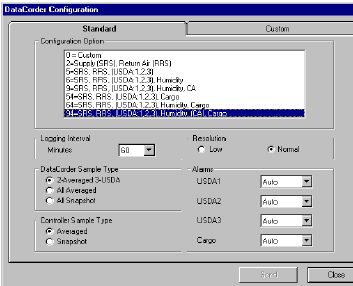
If configured for USDA probes, the following is a summary of the steps required to initiate a USDA Cold Treatment. Refer to the DataLINE User manual 62-10629 for more details.
1.Ensure the DataCORDER is configured as follows:
a.DataCORDER is configured for USDA probes, and logging interval set for 60 minutes.
b.Sensor is set to “2 Averaged 3-USDA.”
c.The resolution is set to “Normal.”
Figure 4.7 DataCorder Configuration Screen
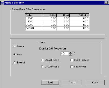
2.Calibrate the three USDA probes by ice bathing the probes and performing the calibration function with the DataLINE. This calibration procedure generates the probe offsets which are stored in the controller and applied to the USDA sensors for use in generating sensor type reports. See Figure 4.8.
Figure 4.8 DataCorder Probe Calibration Screen
3.Pre-cool the container to the treatment temperature or below.
4.Install the DataCORDER module battery pack (if not already installed).
5.Place the three probes. Refer to USDA Treatment Manual for directions on placement of probes in fruit and probe locations in container.
Sensor 1 |
Place the first sensor, labeled USDA1, in a box at the top of the stack of the fruit nearest to the air return intake. |
Sensor 2 |
Place the second sensor, labeled USDA2, slightly aft of the middle of the container, halfway between the top and bottom of the stack. |
Sensor 3 |
Place the third sensor, labeled USDA3, one pallet stack in from the doors of the container, halfway between the top and bottom of the stack. |
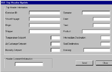
6.To initiate USDA recording, connect the personal computer and Enter ISO header information using the DataLINE software. See Figure 4.9.
a.Enter ISO header information.
b.Enter a trip comment if desired.
Figure 4.9 DataCorder ISO Trip Header Screen
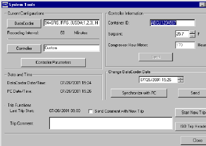
c.Using the System Tools screen in the DataLINE software perform a “trip start.” See Figure 4.10.
Figure 4.10 DataCorder Systems Tool Screen
4.8.1Automatic Cold Treatment (ACT) Cd51
Cold Treatment has been employed as an effective post-harvest method for the control of Mediterranean and certain other tropical fruit flies. Exposing infested fruit to temperatures of 2.2°C (3.6°F) or below for specific time periods results in the mortality of various life stages for this group of insects.
Automated Cold Treatment (ACT) in the Carrier Transicold unit is a method to simplify the task of completing cold treatment by automating the process of changing the setpoints. ACT is set up through function code Cd51. Refer to Function Code table in this manual for Cd51 menu processing and displays.
ACT, setup with Cd51, and Automatic Setpoint Change (ASC), setup with Cd53, will not work simultaneously. Setting one will deactivate the other.
Procedure to Set ACT:
1.Enter the required cargo setpoint. It must be lower than the treatment temperature discussed in step 5.
2.Press the CODE SELECT key.
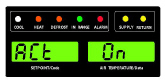
3.Use the Arrow keys to scroll to Cd51, and then press the ENTER key.
4."ACt" is now displayed in the left display and the right will display "Off". Use the Arrow keys to bring up "On" in the right display and press the ENTER key.
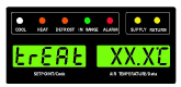
5.“trEAt" is now displayed in the left display and the right will be flashing the last setting (shown as XX.X°C). Use the Arrow keys to select the desired cold treatment setpoint and press the ENTER key.
"trEAt" is the maximum value that the USDA probes need to remain below, to pass the Cold Treatment protocol. For instance, if the treat value is set at 35.0°F (1.7°C) then the USDA probe temperatures must remain below 35.0°F (1.7°C) to pass.
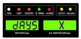
6."dAyS" is now displayed in the left display and the right will be flashing. Use the Arrow keys to select the desired days for cold treatment and press the ENTER key.
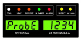
7."ProbE" is now displayed in the left display and the right will display the probe numbers that are connected. Press the ENTER key. For instance, if "1234" is displayed, then all four of the probes are connected.
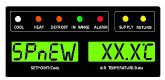
8."SPnEW" is now displayed in the left display and the right will be flashing. Use the Arrow keys to select the desired setpoint after the cold treatment process has successfully completed and press the ENTER key. This would be the final temperature prior to the delivery of the cargo.
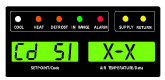
9.Cd51 is now displayed in the left display and the right will display days / hours remaining in cold treatment.
10.The unit will start to countdown once all detected USDA probes have reached the specified cold treatment temperature. The cold treatment process will continue until the specified number of days is reached. During operation, Cd51 will show the number of days and hours remaining in the cold treatment.
Once the cold treatment process has been initiated, setpoint change via the keypad is disabled.
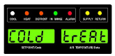
11.While the unit is operating in ACT mode, the left hand display will alternate between "COLd" and setpoint. The right hand display will alternate between "trEAt" and the cargo temperature. Once the treatment time has been completed, the setpoint temperature will increase to the "SPnEW" setting chosen in step 8.
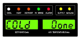
12.When the cold treatment process is complete, the "SPnEW" setpoint will be displayed in the left hand display and cargo temperature in the right hand display, alternating with "COLd" "Done". "COLd" "Done" will continue to alternate with the setpoint and cargo temperature until ACT is turned off.
Procedure to Turn ACT OFF:
ACT will be automatically turned off with a TripStart, or if a Pretrip is initiated.
1.To manually turn ACT Off, press the CODE SELECT key.
2.Use the Arrow keys to scroll to Cd51, and then press the ENTER key.
3.Use the Arrow keys to bring up "Off" in the right display and press the ENTER key.
4.8.2Automatic Setpoint Change (ASC) Cd53
Automatic Setpoint Change (ASC) allows up to 6 setpoint changes to be pre-programmed over defined periods of time using Cd53.
1.Press the CODE SELECT key.
2.Use the Arrow keys to scroll to Cd53, then press the ENTER key.
3.Use the Arrow keys to scroll to ON, then press the ENTER key. If ASC is already ON, selecting OFF will terminate ASC.
4.Select the desired number of setpoint changes (nSC) by scrolling through the available “flashing” options (1 – 6) in the right display, then press the ENTER key.
5.Select the initial setpoint: With (SP 0) in the left display, select by scrolling to the desired “flashing” setpoint in the right display and press ENTER.
6.Select the days desired for initial setpoint (SP 0): With (DAY 0) in the left display, select by scrolling to the desired “flashing” days (1 to 99) in the right display and press ENTER.
7.Select the next setpoint (SP 1): With (SP 1) in the left display, select by scrolling to the desired “flashing” setpoint in the right display and press ENTER.
8.Continue to select each additional setpoint.
9.Select a final setpoint (SP x): With (SP x) in the left display, select by scrolling to the desired “flashing” setpoint in the right display and press ENTER.
While the unit is operating in ASC mode, the left hand display will alternate between current unit setpoint and “ASC”. The right hand display will alternate between current control temperature and “ACtvE”. The user can determine the amount of time left at the current setpoint by selecting Cd53. The amount of time left will be displayed in the right display (XX (days) / XX (hours). By sequentially pressing ENTER, set parameters can be viewed.
At completion of ASC mode, the left hand display will alternate between current unit setpoint “ASC”. The right hand display will alternate between current control temperature and “Done”.
The display will remain this way until ASC is turned off. The user can determine the date of completion by selecting Cd53. With (done) in the left display, the date of completion will be displayed in the right display (Month / Day).
ASC can be manually turned off by selecting Cd53, scrolling to “Off” and pressing the ENTER key.
ACS will be automatically turned off after three days without power, or if a Pre-trip is initiated.
ACS (Cd53) will work independently of Automatic Cold Treatment (ACT) (Cd51). Setting one deactivates the other.
4.9Controller Configuration Variables
Configuration numbers not listed are not used in this application. These items may appear when loading configuration software to the controller but changes will not be recognized by controller programming.
Code |
Title |
Description |
|---|---|---|
If the function is not applicable, the display will read “-----” |
||
Display Only Functions |
||
Cd01 |
VFD (%) |
This is the percent capacity that the VFD is currently running at ranging from 0 - 100%. Therefore, this is the speed of the compressor as a percentage. |
Cd03 |
VFD Status |
This is the current feedback value from the VFD. This code will display output current (Amperes) by default. Press the ENTER key to take the interface down into a selection menu. The arrow keys will allow the operator to cycle forwards and backwards through the following VFD-related quantities: “CUr” (current draw in amps): x.x ranging from 0 to 99.9 “PEr” (speed of compressor as %): x ranging from 0 to 100 POW (power draw displayed in kilowatts): x.x ranging from 0.0 to 99.9 Press the ENTER key again to cause the selected quantity to be pulled up as default, in future code select operations. Press the CODE SELECT key in this selection menu to cancel the current selection activity, and ascend into the main code selection menu. |
Cd04
Cd05
Cd06 |
Line Current, Phase A
Line Current, Phase B
Line Current, Phase C |
The current is measured on three legs. The current measured is used for control and diagnostic purposes. For control processing, the highest of the Phase A and B current values is used for current limiting purposes. Phase C is used for compressor current draw measurement. For diagnostic processing, the current draws are used to monitor component generalization. Whenever a heater or a motor is turned ON or OFF, the current draw increase / decrease for that activity is measured. The current draw is then tested to determine if it falls within the expected range of values for the component. Failure of this test will result in a Pre-trip failure or a control alarm indication. |
Cd07 |
Mains Power Voltage |
The main supply voltage is displayed. |
Cd08 |
Mains Power Frequency |
The value of the main power frequency is displayed in Hertz. The frequency displayed will be halved if either fuse F1 or F2 is bad (alarm code AL21). |
Cd09 |
Ambient Air Temperature |
The ambient sensor reading is displayed. |
Cd10 |
Evaporator Refrigerant Temperature (ETS) |
The evaporator temperature of refrigerant measured leaving the evaporator. |
Cd11 |
Compressor Discharge Temperature (CPDS) |
The compressor discharge temperature is displayed in °C or (°F). |
Cd12 |
Compressor Suction Port Pressure (SPT) |
Bar (°C) presented with decimal. PSI (°F) no decimal. |
Cd13 |
Flash Tank Pressure (FPT) |
Bar (°C) presented with decimal. PSI (°F) no decimal. |
Cd14 |
Compressor Discharge Pressure (DPT) |
Bar (°C) presented with decimal. PSI (°F) no decimal. |
Cd15 |
Unloader |
The status of the valve is displayed (“OPEn” − “CLOSE”). |
Cd16 |
Compressor Motor Hour Meter, Unit Run Time Hour Meter |
This code displays the compressor motor hours. Unit run time can be viewed by pressing the ENTER key while in Cd16. Total hours are recorded in increments of 10 hours (i.e., 3000 hours is displayed as 300). Compressor Motor Hour Meter display can be reset to 0 by pressing and holding the ENTER key for 5 seconds. The Unit Run Time Hour Meter cannot be reset using this code. |
Cd17 |
Relative Humidity % |
Humidity Sensor (HS) reading is displayed. This code displays the relative humidity, as a percent value. |
Cd18 |
Software Revision Number |
The software revision number is displayed. |
Cd19 |
Battery Check |
Request battery test and display results. After selecting Cd19, press the ENTER key to run the battery test. “——“, “btESt”, “PASS”, “”LOW”, “FAIL”. Press and hold the ALT key for 2 seconds, then press the ENTER key with ALT key still held down to clear the “Chargeable Battery Required” flag and then the test is run. If ENTER is not pressed in 5 seconds, the controller returns to display the setpoint. |
Cd20 |
Container Unit Model Number / Configuration |
This code displays the model for which the controller is configured. (i.e., 69NT40-601-001 the display will show 01001. The model number for the unit is listed on the Unit Nameplate, see Figure 2.1. |
Cd21 |
Capacity Mode: Unloaded, Standard, Economized |
Displays the current mode of operation “Unloaded, Standard, Economized,” the mode of operation will be displayed as (“unld”, “Std”, “Econ”). |
Cd22 |
Compressor Run State |
Displays the current compressor run state (“OFF”, “ON”). |
Cd23 |
Evaporator Fan State |
Displays the current evaporator fan state (“OFF”, “LO”, “HI”). |
Cd25 |
Time Remaining Until Defrost |
This code displays the time remaining until the unit goes into defrost (in tenths of an hour). This value is based on actual accumulated compressor running time. |
Cd26 |
Defrost Termination Sensor Temperature |
Defrost Temperature Sensor reading is displayed. |
Configurable Functions |
||
Function codes Cd27 through Cd37 are user-selectable functions. The operator can change the value of these functions to meet the operational needs of the container. |
||
Cd27 |
Defrost Interval |
This is the desired period of time between defrost cycles. “AUTO”, “OFF”, 3, 6, 9, 12, 24 Hours. Factory default is “AUTO”. |
Cd28 |
Standard Temperature Unit |
This parameter determines the default units (metric or British) for the system. The opposite units may be temporarily displayed with the C/F key. This function code will display “—−“ if the controller Degree Celsius Lockout option is set to F. The factory default value is Celsius units. |
Cd29 |
User Selectable Failure Response Code |
This is the desired action to be taken should an alarm occur which severely limits the capability of the control system. Depending upon what alarm has occurred, the actual action taken may not be the same as the desired failure action. The user selects one of two possible actions as follows: A - Evaporator Fan Only (Evap fans on high speed, n/a with frozen setpoints.) d - Full System Shutdown - Factory Default (Shut down every component in unit.) |
Cd30 |
In-Range Tolerance |
The in-range tolerance will determine the band of temperatures around the setpoint which will be designated as in-range. If the control temperature is in-range, the in-range light will be illuminated. There are four possible values: 1 = +/- 0.5°C (+/- 0.9°F) 2 = +/- 1.0°C (+/- 1.8°F) 3 = +/- 1.5°C (+/- 2.7°F) 4 = +/- 2.0°C (+/- 3.6°F) - Factory Default |
Cd32 |
System Current Limit |
The highest current draw of 460VAC Line Current Phase A, B, C is compared to this limit and unit capacity may be reduced to limit current draw if current limit is exceeded. The five values for 460 VAC operation are: 15, 17, 19, 21, or 23 amperes. The factory default setting is 21 amperes. |
Cd33 |
Humidity Setpoint |
This is the value in percent to which the system will dehumidify. There are configuration variables that determine whether dehumidification is installed. In the test mode, the setpoint will be temporarily set to 1%, allowing the test of dehumidification. After 5 minutes, the normal setpoint is restored. If Pre-trip is initiated, this value will be set to “OFF” automatically. |
Cd35 |
Bulb Mode |
The current state of the bulb mode option. “−−−−“, “nOr”, “bULb” |
Cd36 |
Evaporator Fan Speed |
This is the desired evaporator fan speed for use during the bulb mode option. “−−−−“, “ALt”, “LOW”, “HI” |
Cd37 |
Variable DTT Setting |
This is the variable defrost termination thermostat setting to be used with the optional bulb mode functionality. “—−−“, “nOr” |
Display Only Functions |
||
Cd38 |
Secondary Supply |
This item is only displayed if the DataCORDER is configured OFF and configured for a four probe system. Dashes are displayed otherwise. |
Cd39 |
Secondary Return |
This item is only displayed if the DataCORDER is configured OFF and configured for a four probe system. Dashes are displayed otherwise. |
Cd40 |
Container ID |
Cd40 is configured at commissioning to read a valid container identification number. The reading will not display alpha characters; only the numeric portion of the number will display. See Section 7.19.3 Controller Programming Procedure for additional information. |
Cd45 |
Vent Position |
This function code will be dashed out if not configured for VPS. This function code displays current vent position in units of 5 CMH (units displayed as “CM”) or closes CFM (units displayed as “CF”) depending on the selection of Cd 46 (Airflow display units), Cd 28 (Metric/Imperial) or the pressing of the deg C/F key. CFM displayed as “CF”, CMH displayed as “CM”. Values: 0 to 240 for UPPER / 0 to 225 for LOWER |
Cd46 |
Air Flow Display Units |
Selects the airflow units to be displayed by Function Code 45 (Cd 45) if configured for Vent Position Sensor or displayed by “FLO” under Cd 43 if configured for Autoslide. CF= Cubic Feet per Minute, CM=Cubic Meters per Hour, bOth=Displays either CF or CM depending on the setting of Cd 28 (Metric/Imperial) or the pressing of the degree C/F key. Default − “bOth” If configured for Vent Position Sensor or Autoslide |
Cd48 |
Dehumidification / Bulb Cargo Mode Parameter Selection |
Initially Cd48 will display current dehumidification-mode; bUlb - bulb cargo mode, dEhUM - normal dehumidification, or OFF - off. This display is steady. Press the ENTER key to take the interface down into a hierarchy of parameter selection menus (mode, setpoint, evaporator speed, DTT setting). Press the ENTER key in any parameter selection menu to commit to selection of the currently displayed parameter and cause the interface to descend into the next parameter selection menu. All parameter selection menus alternate between a blank display and the current selection in the right hand display. Press the CODE SELECT key in a selection menu to cancel the current selection activity and ascend back up to the next higher selection menu (or to Cd48 display mode if that is the next higher). If the operator does not press any key for five seconds, the interface reverts to normal system display and the current selection menu is canceled, but any previously committed changes are retained. Available parameters and parameter ranges are a function of configuration options and previously selected parameters as indicated above. Whenever any Pre-trip test is initiated, dehumidification mode goes to OFF. Whenever dehumidification mode goes to OFF: •Dehumidification control setpoint goes to 0% RH internally but will then initialize to 95% RH when dehumidification mode leaves OFF. •Evaporator speed select goes to Alt for units without PWM Compressor Control (Cnf57 = Out), Evaporator speed select goes to Hi for units with PWM Compressor Control (Cnf57 = In). •DTT setting goes to 25.6°C or 18.0°C, depending on Cnf41. Whenever dehumidification-mode is set to bUlb, DTT setting goes to 18.0°C if it had been set higher. Whenever dehumidification-mode is set to dEhUM, DTT setting goes to 25.6°C or 18.0°C, depending on Cnf41. For units without PWM Compressor Control (Cnf57 = Out): •Whenever dehumidification control setpoint is set below 65% RH evaporator speed select goes to LO if it had been set to Hi. •Whenever dehumidification control setpoint is set above 64% RH evaporator speed select goes to Alt if it had been set to LO. For units with PWM Compressor Control (Cnf57 = In): •Whenever dehumidification control setpoint is below 60% RH, evaporator fan speed is set to LO, the user can set evaporator fan speed to Hi via the keypad. •Whenever dehumidification control setpoint is set equal to or above 60% RH, the evaporator fan speed is set to Hi, the user has the ability to set the evaporator fan speed to LO via the keypad. |
Cd49 |
Days Since Last Successful Pre-trip |
Display number of days since last successful completion. Press the ENTER key for number of days since successful Pre-trip completion for Auto1, Auto2, and Auto3 in sequence. Press the CODE SELECT key to step back through list and ultimately exit CD49 display. |
Cd51 |
Automatic Cold Treatment Parameter Selection |
Automatic Cold Treatment (ACT) mode: Cd51 increments of (1 day)_(1hr), Display: default “0_0 “ “done” mm-dd this will be display is ACT has completed “ACt” value “On” “OFF” or “----“Display / Select: default “OFF“ “trEAt” value °C / °F on 0.1 degree increments Display / Select: default “0.0°C“ “DAyS” value “0-99” increments of 1 Display / Select: default “0” “ProbE” value Probe positions ex ’1 2 _ 4’ ’1 _ 3 _’ Display: default “---- “ “SPnEW” value °C / °F on 0.1° increments Display / Select: default “10.0°C “ Initially Cd51 will display current countdown timer increments of (1 day)_(1hr), default “0_0”. See Section 4.8.1 for procedure to set ACT using Cd51. Pressing the ENTER key will take the interface down into a hierarchy of parameter selection menus (act, treat, days, probe and spnew setting). Pressing the ENTER key in any of the parameter selection menus commits to selection of the currently displayed parameter and causes the interface to descend into the next parameter selection menu. All parameter selection menus alternate between a blank display and the current selection in the right hand display. Pressing the CODE SELECT key in a selection menu cancels the current selection activity and ascends back up to the next higher selection menu (or to Cd51 display mode if that is the next higher). If the operator does not press any key for five seconds, the interface reverts to normal system display and the current selection menu is cancelled, but any previously committed changes are retained. Parameter with the exception of “Act” may not be altered if Cd51 is re-entered if “Act” is “On”. When ACT has completed including reaching the new setpoint “done” on the left display and the MONTH DAY of completion on the right display will be displayed as the second entry in the menu. Turning ACT off clears this entry. This action also resets Cd51 to initial time remaining. ACT must then be turned on to view or modify the additional parameters. Whenever any auto Pre-trip test or Trip Start is initiated, ACT mode goes to OFF. |
Cd53 |
Automatic Setpoint Change Mode Parameter Selection |
Automatic Setpoint Change (ASC) Mode: Cd53 increments of (1 day)_(1hr), Display: default “0_0” “done” mm-dd this will be display is ASC has completed “ASC” value “On” “OFF” Display / Select: default “OFF“ “nSC” value “1 - 6” (This is the value “n” for the subsequent entries). “SP (n-1)” value °C / °F on 0.1 degree increments Display / Select: default “10.0°C“ “DAY (n-1)” value “1 – 99” increments of 1 Display / Select: default “1“ “SP (n)” value °C / °F on 0.1 degree increments Display / Select: default “10.0°C Initially Cd53 will display current countdown timer increments of (1 day)_(1hr), default “0_0”. Pressing the ENTER key will take the interface down into a hierarchy of parameter selection menus, (mode, act, treat, days, probe and spnew setting). Pressing the ENTER key in any of the parameter selection menus selects the currently displayed parameter and causes the interface to descend into the next parameter selection menu. All parameter selection menus alternate between a blank display and the current selection in the right hand display. Pressing the CODE SELECT key in a selection menu cancels the current selection activity and ascends back up to the next higher selection menu (or to Cd53 display mode if that is the next higher). If the operator does not press any key for five seconds, the interface reverts to normal system display and the current selection menu is cancelled, but any previously committed changes are retained. Available parameters and parameter ranges are a function of configuration options and previously selected parameters as indicated above. Parameter with the exception of “ASC” may not be altered if Cd53 is re-entered if “ASC” is “On”. When ASC has completed including reaching the last setpoint “done” on the left display and the MONTH DAY of completion on the right display will be displayed as the second entry in the menu. Turning ASC off clears this entry. This action also resets Cd53 to initial time remaining. ASC must then be turned on to view or modify the additional parameters. Whenever any auto Pre-trip test or Trip Start is initiated, ASC mode goes to OFF. |
Cd54 |
Superheat Values |
Evaporator superheat: Evaporator leaving temperature minus suction saturation temperature as calculated from suction pressure. |
Cd55 |
Discharge Superheat |
Cd55 will display discharge superheat (discharge temperature minus discharge saturation temperature as calculated from discharge pressure) values in C / F as calculated by the discharge temperature minus the discharge saturation temperature as calculated from discharge pressure. “-----” will be displayed if selection is not valid. |
Cd58 |
Water Pressure Switch State |
This code is only displayed if the unit is configured for water-cooled condenser option. Values for this code are: “----”, “OPEN”, “CLOSE”. |
Cd61 |
VFD Bypass Mode |
When this code is active it signifies the unit is operating in a LIMP HOME MODE Condition. Cd61 is locked out, and should only be activated after the VFD bypass procedure has been completed (see Section 7.20.2). |
Cd68 |
EEV % Opening |
Displays the current percent opening of EEV (0-100%). |
Cd69 |
HPXV % Opening |
Displays the current percent opening of HPXV (0-100%). |
Figure 4.11 Alarm Troubleshooting Sequence
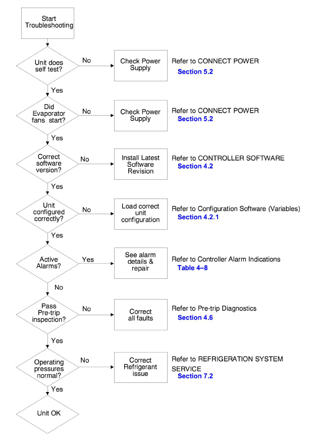
4.11Controller Alarm Indications
AL03 |
Loss of Superheat Control |
|
|---|---|---|
Cause: |
Superheat has remained below 1.66°C (3°F) degrees for five minutes continuously while the compressor is running. Compressor is drawing more than 2.0 amps, compressor pressure ratio is greater than 1.8, and Electronic Expansion Valve (EEV) is at 0% open. |
|
Component |
Electronic Expansion Valve (EEV) |
|
Troubleshooting |
Allow unit to run. Monitor superheat control (Cd54) and EEV position (Cd68). Remove the service panel and inspect the EEV for icing. Stepper driver may be installed to attempt to manually control the valve driver. Check connections between the EEV and power pack and also between the power pack and controller. Check resistance of EEV coils. |
|
Corrective Action |
If the problem may be corrected using a manual electronic stepper drive tool, replace the EEV control module. If the unit does not respond to icing on the EEV outlet (Evaporator inlet) it may indicate a physically damaged valve. Replace the EEV. |
|
Component |
Compressor |
|
Troubleshooting |
Check VFD Speed (Cd01), Suction Pressure (Cd12), and Flash Tank Pressure (Cd13). If the compressor speed is greater than 70% and the flash tank pressure is approximately equal to suction pressure with the HPXV controlling at less than 25% (Cd69), then there may be a compressor first stage failure. This condition will also increase compressor discharge temperature (Cd11) and may also demonstrate AL19 alarms. Heavy icing on flash tanks will also be seen. |
|
Corrective Action |
|
|
Component |
Evaporator Temperature Sensors (ETS and ETS1) |
|
Troubleshooting |
Verify the accuracy of the sensors ETS and ETS1. Refer to the Sensor Checkout Procedure (Section 7.22). |
|
Corrective Action |
Replace ETS or ETS1 if it is defective. |
|
Component |
Evaporator Fans |
|
Troubleshooting |
Confirm fans are operating properly. |
|
Corrective Action |
Replace fan(s) if it is defective. Refer to Evaporator Fan Motor Assembly (Section 7.13). |
|
AL05 |
Manual Defrost Switch Failure |
|
|---|---|---|
Cause: |
Controller has detected continuous Manual Defrost Switch activity for five minutes or more. |
|
Component |
Keypad |
|
Troubleshooting |
Power cycle the unit. |
|
Corrective Action |
Resetting the unit may correct problem. Monitor the unit. If the alarm reappears after 5 minutes, replace the keypad. |
|
AL06 |
Keypad or Keypad Harness Failure |
|
|---|---|---|
Cause: |
Controller has detected continuous activity from one of the keypad keys. |
|
Component |
Keypad or Harness |
|
Troubleshooting |
Power cycle the unit. |
|
Corrective Action |
Resetting the unit may correct problem. Monitor the unit. If the alarm reappears, replace the keypad and harness. |
|
AL07 |
Fresh Air Vent Open |
|
|---|---|---|
Cause: |
The Vent Position Sensor (VPS) is reading greater than 0 CMH while the unit is in frozen mode. |
|
Component |
Vent Position Sensor (VPS) |
|
Troubleshooting |
Manually reposition the vent and confirm the position using Cd45. Refer to VPS Service (Section 7.21). |
|
Corrective Action |
If unable to obtain a zero reading, replace the defective VPS. |
|
AL13 |
VFD Communication Alarm |
|
|---|---|---|
Cause: |
ML3 controller loses reliable communication with the VFD (no response for 3 seconds). Make sure that the latest unit software is installed and re-run the unit to see if the alarm comes back. If the alarm does not clear, then follow troubleshooting. |
|
Component |
VFD, VFD Bridge, Controller |
|
Troubleshooting |
Check continuity of the KH connector. Power cycle the unit. |
|
Corrective Action |
If the alarm immediately re-occurs after a few seconds, allow to remain active and perform the VFD Bypass procedure (Section 7.20.2). |
|
|
Component |
Compressor IP |
|
Troubleshooting |
Confirm motor IP and HPS is closed between KA2 and TP2. |
|
Corrective Action |
If IP is open, replace the compressor. If HPS is open, replace the HPS. |
AL14 |
Phase Sequence Detect Fault |
|
|---|---|---|
Cause: |
Controller is unable to determine the correct phase relationship. |
|
Component |
N/A |
|
Troubleshooting |
Power cycle the unit. |
|
Corrective Action |
Resetting the unit may correct the problem. Monitor the unit. |
|
Component |
Wiring |
|
Troubleshooting |
Check unit wiring. |
|
Corrective Action |
Correct wiring. |
|
Component |
Current Sensor |
|
Troubleshooting |
Compare function codes Cd04, Cd05, and Cd06 against manual current draw readings. |
|
Corrective Action |
Replace the current sensor if there is discrepancy between manual and display readings. |
|
AL15 |
Loss of Cooling |
|
|---|---|---|
Cause: |
Evaporator efficiency monitor has detected a loss of system capacity, likely due to a drop in refrigerant charge density. |
|
Component |
Refrigerant Charge |
|
Troubleshooting |
Check units for leaks, paying careful attention to high side fittings. Check Pressure Relief Valves (Section 7.7) to see if refrigerant has been released and replace if necessary. Check for signs of unit running short of refrigerant: Codes Cd12 and Cd13 along with high superheat at Cd54 and EEV open more than standard operation, up to 100% at Cd68. |
|
Corrective Action |
Rectify refrigerant leaks. Remove refrigerant charge (Section 7.2.5), evacuate the unit (Section 7.2.7), and recharge the unit to rated charge (Section 7.2.8). |
|
Component |
Evaporator |
|
Troubleshooting |
Check for excessive ice buildup on the coil, T-bar blockages, or fouling. |
|
Corrective Action |
Defrost the coil. |
|
AL18 |
Discharge Pressure High |
|
|---|---|---|
Cause: |
Discharge pressure is above 131 bar (1900 psig). |
|
Component |
High Pressure Expansion Valve (HPXV), Electronic Expansion Valve (EEV) |
|
Troubleshooting |
Power cycle the unit. Check operation of the valves during power up. Verify that the HPXV coil is fully seated on the stem of the HPXV body (see Section 7.15.2). |
|
Corrective Action |
Alarm will clear once pressures are within operating limits. |
|
|
Component |
Refrigerant Lines |
|
Troubleshooting |
Measure temperatures before and after all fittings and braze joints, paying careful attention to screen locations. Temperature drops may indicate internal blockages. Unit over-charge or under-charge may create pressure control problems related to charge density and compression ratio. Ensure that the unit refrigerant charge is within operational specifications for the model. |
|
Corrective Action |
Rectify system blockages. Remove refrigerant charge (Section 7.2.5), evacuate the unit (Section 7.2.7), and recharge the unit to rated charge (Section 7.2.8). |
|
Component |
Gas Cooler Fan and Motor |
|
Troubleshooting |
Check the gas cooler fan and motor for excessive coil fouling and proper operation. |
|
Corrective Action |
Replace the gas cooler fan motor. |
AL19 |
Discharge Temperature High |
|
|---|---|---|
Cause: |
Discharge temperature is above 135°C (275°F). |
|
Component |
Restrictions in the refrigeration system |
|
Troubleshooting |
Check the unit for air flow restrictions. |
|
Corrective Action |
Clean or remove any debris from the coils. |
|
Component |
Non-condensables in the refrigeration system. |
|
Troubleshooting |
With the unit off, allow system to stabilize to ambient temperature. Check system pressure against the Pressure / Temperature Chart for R744 (Table 7–4). Refer to function codes Cd12, Cd13 and Cd14. |
|
Corrective Action |
Remove refrigerant charge (Section 7.2.5), evacuate the unit (Section 7.2.7), and recharge the unit (Section 7.2.8). |
|
Component |
Compressor |
|
Troubleshooting |
Check VFD Speed (Cd01), Suction Pressure (Cd12), and Flash Tank Pressure (Cd13). If the compressor speed is greater than 70% and the Flash Tank pressure is approximately equal to suction pressure with the High Pressure Expansion Valve (HPXV) controlling at less than 25% (Cd69), there may be a compressor first stage failure. This condition will also increase compressor discharge temperature (Cd11) and may also demonstrate AL03 alarms. |
|
Corrective Action |
If the alarm persists, it may indicate a failing compressor. Replace the compressor, refer to Compressor Service (Section 7.3). |
|
Component |
Refrigerant Charge |
|
Troubleshooting |
Check unit for leaks, paying careful attention to high side fittings. Unit over-charge or under-charge may create pressure control problems related to charge density and compression ratio. Ensure the unit refrigerant charge is within operational specifications for the model. Check Pressure Relief Valves (Section 7.7) to see if refrigerant has been released and replace if necessary. Check for signs that the unit is running short of refrigerant. Check Compressor Suction Pressure (Cd12) and Flash Tank Pressure (Cd13). Check for high superheat (Cd54) and EEV open more than standard operation, up to 100% (Cd68). |
|
Corrective Action |
Rectify refrigerant leaks, vacuum and re-charge the system to rated charge. |
|
AL20 |
Control Contactor Fuse (F3) |
|
|---|---|---|
Cause: |
Control power fuse (F3A or F3B) is open. |
|
Component |
Fuse F3A |
|
Troubleshooting |
If fuse F3A is open, check PA, PB, and CH coils for short to ground. If a short is found, the coil is defective. Check ESV coil resistance at TP7 to TP9, and USV coil resistance at TP1 to TP9. If short to ground, or if resistance is less than 4 ohms, the coil is defective. |
|
Corrective Action |
Replace the defective coil. Replace the fuse. |
|
Component |
Fuse F3B |
|
Troubleshooting |
If fuse F3B is open, check contactor coils GF, GS, ES, EF, HR, for a short to ground. If a short is found, the coil is defective. |
|
Corrective Action |
Replace the defective coil. Replace the fuse. |
|
Component |
Controller |
|
Troubleshooting |
Check voltage at QC1. If voltage is present, it indicates a defective microprocessor. |
|
Corrective Action |
Refer to Controller Service (Section 7.19). |
|
AL21 |
Control Circuit Fuse (F1/F2) |
|
|---|---|---|
Cause: |
One of the 18 VAC controller fuses (F1 / F2) is open. Refer to code Cd08. |
|
Component |
System Sensors |
|
Troubleshooting |
Check system sensors for short to ground. |
|
Corrective Action |
Replace defective sensor(s). |
|
Component |
Wiring |
|
Troubleshooting |
Check wiring for short to ground. |
|
Corrective Action |
Repair as needed. |
|
Component |
Controller |
|
Troubleshooting |
Controller may have an internal short. |
|
Corrective Action |
Replace controller. Refer to Controller Service (Section 7.19). |
|
AL22 |
Evaporator IP |
|
|---|---|---|
Cause: |
Evaporator motor internal protector (IP) is open. |
|
Component |
Evaporator Motor |
|
Troubleshooting |
Shut down the unit, disconnect power and check evaporator motor IP at plug connection pins 4 & 6. |
|
Corrective Action |
Replace the defective evaporator fan motor. Refer to Evaporator Fan Motor Service (Section 7.13). |
|
AL23 |
Loss of Phase B |
|
|---|---|---|
Cause: |
Controller fails to detect current draw. |
|
Component |
Incoming Power |
|
Troubleshooting |
Check incoming power source. |
|
Corrective Action |
Correct power source as required. |
|
AL24 |
Compressor IP |
|
|---|---|---|
Cause: |
Compressor internal protector (IP) is open for greater than five seconds. |
|
Component |
Compressor |
|
Troubleshooting |
Confirm motor IP is open at KA2 to KB9. Verify the High Pressure Switch (HPS) is closed. |
|
Corrective Action |
Monitor the unit. If the alarm remains active or is repetitive, replace the compressor at the next available opportunity. Refer to Compressor Service (Section 7.3). |
|
AL25 |
Gas Cooler Motor IP |
|
|---|---|---|
Cause: |
Gas cooler fan motor internal protector (IP) is open. |
|
Component |
Insufficient Air Flow |
|
Troubleshooting |
Shut down the unit and check the gas cooler fan for obstructions. |
|
Corrective Action |
Remove obstructions. |
|
Component |
Gas Cooler Fan Motor |
|
Troubleshooting |
Shut down the unit, disconnect power and check the gas cooler fan motor IP at plug connection pins 4 & 6. Or, on the controller between TP3 and TP4 if the Water Cooled Condenser is not fitted or water is disconnected. |
|
Corrective Action |
Replace defective gas cooler fan motor. Refer to Gas Cooler Fan Motor Assembly Service (Section 7.9). |
|
AL26 |
All Sensors Failure: Supply/Return Probes |
|
|---|---|---|
Cause: |
Sensors detected as out of range. |
|
Component |
Sensors |
|
Troubleshooting |
Perform Pre-trip P5. |
|
Corrective Action |
If P5 passes, no further action is required. If P5 fails, replace the defective sensor as determined by P5. Refer to Temperature Sensor Service (Section 7.22). |
|
AL27 |
Analog to Digital Accuracy Failure |
|
|---|---|---|
Cause: |
Controller AD converter faulty. |
|
Component |
Controller |
|
Troubleshooting |
Power cycle the unit. If the alarm persists, it indicates a defective microprocessor. |
|
Corrective Action |
Replace the defective microprocessor. Refer to Controller Service (Section 7.19). |
|
AL28 |
Low Suction Pressure |
|
|---|---|---|
Cause: |
Suction pressure is less than 5.5 bar (80 psi), or less than 6.2 bar (90 psi) for 300 seconds. |
|
Component |
Refrigerant Charge |
|
Troubleshooting |
Check units for leaks, paying careful attention to high side fittings. Check Pressure Relief Valves (Section 7.7) to see if refrigerant has been released and replace if necessary. Check for signs that the unit is running short of refrigerant. Check Compressor Suction Pressure (Cd12) and Flash Tank Pressure (Cd13). Check for high superheat (Cd54) and Electronic Expansion Valve (EEV) open more than standard operation, up to 100% (Cd68). |
|
Corrective Action |
Rectify refrigerant leaks, vacuum and re-charge the system to rated charge. |
|
Component |
Suction Pressure Transducer (SPT) |
|
Troubleshooting |
Power cycle the unit. |
|
Corrective Action |
Resetting the unit may correct the problem. Monitor the unit. |
|
Troubleshooting |
Confirm accurate SPT pressure readings. Refer to Manifold Gauge Set procedures (Section 7.2). |
|
Corrective Action |
Replace SPT if it is defective. |
|
AL50 |
Air Vent Position Sensor (VPS) |
|
|---|---|---|
Cause: |
Vent Position Sensor (VPS) out of range. |
|
Component |
Vent Position Sensor (VPS) |
|
Troubleshooting |
Make sure the VPS is secure. |
|
Corrective Action |
Manually tighten the panel. |
|
Troubleshooting |
The user is allowed five minutes to make necessary adjustments to the vent setting, and then five minutes of stability are required following the last movement to consider the vent position stable. If vent position changes are detected during the required stability period, an alarm will be generated. The alarm will also be generated if the VPS is invalid. |
|
Corrective Action |
If the alarm persists, replace the VPS or the sensor assembly. |
|
AL51 |
EEPROM Failure |
|
|---|---|---|
Cause: |
Controller Memory Failure Alarm List Failure, bad queue marker, or EEPROM hardware error detected for 3 seconds. |
|
Component |
Controller |
|
Troubleshooting |
Press the ENTER key when “CLEAr” is displayed to attempt to clear the alarm. |
|
Corrective Action |
If the action to clear alarm is successful (all alarms are inactive), alarm 51 will be reset. |
|
Troubleshooting |
Power cycle the unit. If the alarm persists, it indicates defective controller memory. |
|
Corrective Action |
Replace the defective controller. Refer to Controller Service (Section 7.19). |
|
AL52 |
EEPROM Alarm List Full |
|
|---|---|---|
Cause: |
Alarm list queue is full. |
|
Component |
Active Alarms |
|
Troubleshooting |
Repair any alarms in the queue that are active. These are indicated by “AA”. |
|
Corrective Action |
Clear alarms. Refer to the Controller Alarms table (Section 4.5). |
|
AL53 |
Battery Pack Failure |
|
|---|---|---|
Cause: |
Battery voltage low. |
|
Component |
Battery |
|
Troubleshooting |
If this alarm occurs on start up, allow a unit fitted with rechargeable batteries to operate for up to 24 hours to charge rechargeable batteries sufficiently. Once fully charged, the alarm will deactivate. |
|
Corrective Action |
To clear the alarm, press the ENTER and ALT keys simultaneously at the startup of Cd19 (Battery Check). If the alarm persists, replace the battery pack. Refer to Battery Replacement procedure (Section 7.19.5). |
|
AL54 |
Primary Supply Sensor (STS) |
|
|---|---|---|
Cause: |
Invalid Supply Temperature Sensor (STS) reading. |
|
Component |
Supply Temperature Sensor (STS) |
|
Troubleshooting |
Perform Pre-trip P5. |
|
Corrective Action |
If P5 passes, no further action is required. |
|
|
If P5 fails, replace the defective sensor as determined by P5. Refer to Temperature Sensor Service (Section 7.22). |
|
AL56 |
Primary Return Sensor (RTS) |
|
|---|---|---|
Cause: |
Invalid Return Temperature Sensor (RTS) reading. |
|
Component |
Return Temperature Sensor (RTS) |
|
Troubleshooting |
Perform Pre-trip P5. |
|
Corrective Action |
If P5 passes, no further action is required. |
|
|
If P5 fails, replace the defective sensor as determined by P5. Refer to Temperature Sensor Service (Section 7.22). |
|
AL57 |
Ambient Sensor (AMBS) |
|
|---|---|---|
Cause: |
Invalid Ambient Temperature Sensor (AMBS) reading. |
|
Component |
Ambient Temperature Sensor (AMBS) |
|
Troubleshooting |
Test the AMBS. Refer to Temperature Sensor Service (Section 7.22). |
|
Corrective Action |
If AMBS is defective, replace it. Refer to Temperature Sensor Service (Section 7.22). |
|
AL58 |
Compressor High Pressure Safety (HPS) |
|
|---|---|---|
Cause: |
High pressure safety switch has opened and reset within five seconds, triggering a high pressure shutdown state. |
|
Component |
High Pressure Switch (HPS) |
|
Troubleshooting |
Test the HPS. Refer to Checking High Pressure Switch procedure (Section 7.5.1). Run a P7 test to verify the operation of the HPS. |
|
Corrective Action |
Replace the HPS if it is defective. Refer to Sensor Replacement procedure (Section 7.5.2). |
|
Component |
Refrigeration System |
|
Troubleshooting |
Measure temperatures before and after all fittings and braze joints paying careful attention to screen locations. Temperature drops may indicate internal blockages. Unit over-charge may create pressure control problems. Ensure unit refrigerant charge is within operational specifications for the model. Check unit for air flow restrictions. |
|
Corrective Action |
Clean or remove any debris from coils. Rectify system blockages. Remove refrigerant charge (Section 7.2.5), evacuate the unit (Section 7.2.7), and recharge the unit (Section 7.2.8). |
|
Component |
High Pressure Expansion Valve (HPXV) |
|
Troubleshooting |
Verify that the HPXV coil is fully seated on the stem of the HPXV body (see Section 7.15.2). Attempt to manually open the valve with magnet. If this rectifies the problem, replace the stepper motor. Check resistance of HPXV coils. |
|
Corrective Action |
Replace the HPXV. |
|
AL59 |
Heater Termination Thermostat (HTT) |
|
|---|---|---|
Cause: |
Heat Termination Thermostat (HTT) is open. |
|
Component |
Heat Termination Thermostat (HTT) |
|
Troubleshooting |
Check for 24 volts at test point TP10. If there is no voltage at TP10 after unit has reached setpoint, HTT is open. |
|
Corrective Action |
Replace HTT if it is defective. |
|
AL60 |
Defrost Termination Sensor (DTS) |
|
|---|---|---|
Cause: |
Failure of the Defrost Temperature Sensor (DTS) to open. This is an indication of a probable failure of the DTS. It is triggered by the opening of the HTT or the failure of the DTS to go above setpoint within two hours of defrost initiation. After 1/2 hour with a frozen range setpoint, or 1/2 hour of continuous compressor run time, if return air falls below 7°C (45°F), the controller checks to ensure the DTS reading has dropped to 10°C or below. If not, a DTS failure alarm is given and defrost mode is operated using the Return Temperature Sensor (RTS). Defrost mode will be terminated after one hour by the controller. |
|
Component |
Defrost Termination Sensor (DTS) |
|
Troubleshooting |
Test the DTS. Refer to Temperature Sensor Service (Section 7.22). |
|
Corrective Action |
Replace the DTS if it is defective. Refer to Temperature Sensor Service (Section 7.22). |
|
AL61 |
Heater Current Draw Fault |
|
|---|---|---|
Cause: |
Improper current draw during heat or defrost mode. |
|
Component |
Heater(s) |
|
Troubleshooting |
While in heat or defrost mode, check for proper current draw at the Heater Contactors (HR). Refer to Electrical Data (Section 3.4). |
|
Corrective Action |
Replace the heater(s) if it is defective. Refer to Evaporator Coil & Heater Assembly (Section 7.11). |
|
Component |
Contactor |
|
Troubleshooting |
Check voltage at the Heater Contactor (HR) on the heater side. |
|
Corrective Action |
If no voltage present, replace the Heater Contactor (HR) if it is defective. |
|
AL63 |
Current Limit |
|
|---|---|---|
Cause: |
Unit operating above current limit. |
|
Component |
Refrigeration System |
|
Troubleshooting |
Check unit for air flow restrictions. |
|
Corrective Action |
Clean or remove any debris from coils. |
|
Troubleshooting |
Check unit for proper operation. |
|
Corrective Action |
Repair as needed. |
|
Component |
Power Supply |
|
Troubleshooting |
Confirm supply voltage / frequency is within specification and balanced according to Electrical Data (Section 3.4). |
|
Corrective Action |
Correct power supply. |
|
Troubleshooting |
Current limit set too low. Check current limit setting at Cd32. |
|
Corrective Action |
The current limit can be raised (maximum of 23 amps) using Cd32. |
|
AL64 |
Discharge Temperature Sensor (CPDS) |
|
|---|---|---|
Cause: |
Discharge Temperature Sensor (CPDS) out of range. |
|
Component |
Discharge Temperature Sensor (CPDS) |
|
Troubleshooting |
Test the CPDS. Refer to Temperature Sensor Service (Section 7.22). Reference Cd11 for sensor values. |
|
Corrective Action |
Replace the CPDS if it is defective. Refer to Temperature Sensor Service (Section 7.22). |
|
AL65 |
Discharge Pressure Transducer (DPT) |
|
|---|---|---|
Cause: |
Compressor Discharge Pressure Transducer (DPT) is out of range. |
|
Component |
Compressor Discharge Pressure Transducer (DPT) |
|
Troubleshooting |
Confirm accurate DPT pressure readings. Refer to Manifold Gauge Set procedures (Section 7.2). Reference Cd14 for transducer values. |
|
Corrective Action |
Replace the DPT if it is defective. |
|
AL66 |
Suction Pressure Transducer (SPT) |
|
|---|---|---|
Cause: |
Suction Pressure Transducer (SPT) out of range. |
|
Component |
Suction Pressure Transducer (SPT) |
|
Troubleshooting |
Confirm accurate SPT pressure readings. Refer to Manifold Gauge Set procedures (Section 7.2). Reference Cd12 for transducer values. |
|
Corrective Action |
Replace SPT if it is defective. |
|
Troubleshooting |
Monitor the unit. |
|
Corrective Action |
If the alarm persists, it may indicate a failing compressor. Refer to Compressor Service (Section 7.3). |
|
AL67 |
Humidity Sensor (HS) |
|
|---|---|---|
Cause: |
Humidity Sensor (HS) reading out of range. Humidity Sensor (HS) below 2% or greater than four volts. |
|
Component |
Humidity Sensor (HS) |
|
Troubleshooting |
Make sure HS is properly connected in the socket. Make sure HS wires are not damaged. Reference Cd17 for sensor values. |
|
Corrective Action |
Monitor and replace the HS if the alarm persists. |
|
AL68 |
Flash Tank Pressure Transducer Alarm |
|
|---|---|---|
Cause: |
Flash Tank Pressure Transducer (FPT) is out of range. |
|
Component |
Flash Tank Pressure Transducer (FPT) |
|
Troubleshooting |
Confirm accurate FPT pressure readings. It is not possible to check FPT with gauges. Turn off the unit and let the pressure equalize, check that codes Cd12, Cd13 and Cd14 are all equal. |
|
Corrective Action |
Replace the FPT if it is defective. |
|
AL69 |
Evaporator Temperature Sensor (ETS1) |
|
|---|---|---|
Cause: |
Evaporator Temperature Sensor (ETS1) out of range. |
|
Component |
Evaporator Temperature Sensor (ETS1) |
|
Troubleshooting |
Test the ETS1. Refer to Temperature Sensor Service (Section 7.22). Refer to Cd10 for sensor values. |
|
Corrective Action |
Replace the ETS1 if it is defective. |
|
AL70 |
Secondary Supply Sensor (SRS) |
|
|---|---|---|
Cause: |
Secondary Supply Sensor (SRS) is out of range. |
|
|
Component |
Secondary Supply Sensor (SRS) |
|
Troubleshooting |
Perform Pre-trip P5. |
|
Corrective Action |
If P5 passes, no further action is required. If P5 fails, replace the defective sensor as determined by P5. Refer to Temperature Sensor Service (Section 7.22). |
AL71 |
Secondary Return Sensor (RRS) |
|
|---|---|---|
Cause: |
Secondary Return Sensor (RRS) is out of range. |
|
|
Component |
Secondary Return Sensor (RRS) |
|
Troubleshooting |
Perform Pre-trip P5. |
|
Corrective Action |
If P5 passes, no further action is required. If P5 fails, replace the defective sensor as determined by P5. Refer to Temperature Sensor Service (Section 7.22). |
AL72 |
Control Temperature Out of Range |
|
|---|---|---|
Cause: |
After the unit goes in-range for 30 minutes then out of range for a continuous 120 minutes. |
|
|
Component |
Refrigeration System |
|
Troubleshooting |
Ensure that the unit is operating correctly. |
|
Corrective Action |
Power cycle the unit. Control temperature is in-range. Any pre-trip mode resets the timers. |
AL92 |
VFD Internal Fault |
|
|---|---|---|
Cause: |
Internal fault occurred in the Variable Frequency Drive (VFD). |
|
Component |
VFD |
|
Troubleshooting |
Power cycle the unit. |
|
Corrective Action |
If alarm cannot be reset, perform a VFD bypass procedure (Section 7.20.2). |
|
AL93 |
VFD Fan Fault |
|
|---|---|---|
Cause: |
Variable Frequency Drive (VFD) temperature feedback exceeds 55°C (131°F). Make sure that the latest unit software is installed and re-run the unit to see if the alarm comes back. If the alarm does not clear, then follow troubleshooting. |
|
Component |
VFD Fan |
|
Troubleshooting |
Ensure that the fan inlet and outlets are clear and fan is free to rotate. |
|
Corrective Action |
Remove and replace the VFD Fan (Section 7.20.1). |
|
AL94 |
VFD Trip Alarm |
|
|---|---|---|
Cause: |
An internal Variable Frequency Drive (VFD) alarm has been detected. |
|
Component |
Compressor |
|
Troubleshooting |
Verify compressor oil level and condition. |
|
Corrective Action |
Charge compressor with oil. |
|
Component |
VFD |
|
Troubleshooting |
Power cycle the unit. |
|
Corrective Action |
If alarm cannot be reset, perform a VFD bypass procedure (Section 7.20.2). |
|
AL95 |
Gas Cooler Outlet Temperature |
|
|---|---|---|
Cause: |
Gas Cooler outlet temperature is out of range. |
|
Component |
Gas Cooler |
|
Troubleshooting |
Check for dirt, debris and blockage of the Gas Cooler. Check continuity at connector KH. |
|
Corrective Action |
Remove any blockage in the Gas Cooler coil. |
|
Component |
Gas Cooler Temperature Sensor (GCTS) |
|
Troubleshooting |
Check the operation of the GCTS. |
|
Corrective Action |
Replace the GCTS if necessary. See Section 7.8. |
|
AL97 |
High Flash Tank Pressure |
|
|---|---|---|
Cause: |
Flash tank pressure is greater than 104 bar (1508 psi). |
|
Component |
Electronic Expansion Valve (EEV) |
|
Troubleshooting |
Remove the service panel and inspect the EEV for icing. Stepper driver may be installed to attempt to manually control valve driver. |
|
Corrective Action |
If the problem may be corrected using a manual electronic stepper drive tool, replace the EEV control module. If the unit does not respond to icing on the EEV outlet (Evaporator inlet), it may indicate a physically damaged valve. Replace the EEV. Check resistance of EEV coils. |
|
Component |
Refrigerant Charge |
|
Troubleshooting |
High refrigerant charge will over-pressurize the flash tank and prevent economized operation. Check that Flash pressure is not higher than 69 bar (1000 psi) during operation. |
|
Corrective Action |
Remove refrigerant charge (Section 7.2.5), evacuate the unit (Section 7.2.7), and recharge the unit (Section 7.2.8) to rated charge. |
|
Component |
Gas Cooler |
|
Troubleshooting |
Check Gas Cooler fan and motor for excessive coil fouling and proper operation. |
|
Corrective Action |
Replace the Gas Cooler fan motor. |
|
If the controller is configured for four probes without a DataCORDER, the DataCORDER alarms AL70 and AL71 will be processed as Controller alarms AL70 and AL71. Refer to Table 4–5.
The controller performs self-check routines. If an internal failure occurs, an “ERR” alarm will appear on the display. This is an indication the controller needs to be replaced. In the event that a failure occurs and the display cannot be updated, the status LED will indicate the appropriate ERR code using Morse code as shown below.
ERR 0 |
. .−. .−. −−−−− |
|
|---|---|---|
Cause: |
RAM failure |
|
|
Description |
Indicates that the controller working memory has failed. |
ERR 1 |
. .−. .−. . −−−− |
|
|---|---|---|
Cause: |
Program Memory failure |
|
|
Description |
Indicates a problem with the controller program. |
ERR 2 |
. .−. .−. . . −−− |
|
|---|---|---|
Cause: |
Watchdog time-out |
|
|
Description |
The controller program has entered a mode whereby the controller program has stopped executing. |
ERR 3 |
. .−. .−. . . . −− |
|
|---|---|---|
Cause: |
N/A |
|
|
Description |
N/A |
ERR 4 |
. .−. .−. . . . . − |
|
|---|---|---|
Cause: |
N/A |
|
|
Description |
N/A |
ERR 5 |
. .−. .−. . . . . . |
|
|---|---|---|
Cause: |
A−D failure |
|
|
Description |
The controller’s Analog to Digital (A−D) converter has failed. |
ERR 6 |
. .−. .−. −. . . . |
|
|---|---|---|
Cause: |
IO Board failure |
|
|
Description |
Internal program/update failure. |
ERR 7 |
. .−. .−. −−. . . |
|
|---|---|---|
Cause: |
Controller failure |
|
|
Description |
Internal version/firmware incompatible. |
ERR 8 |
. .−. .−. −−−. . |
|
|---|---|---|
Cause: |
DataCORDER failure |
|
|
Description |
Internal DataCORDER memory failure. |
ERR 9 |
. .−. .−. −−−− . |
|
|---|---|---|
Cause: |
Controller failure |
|
|
Description |
Internal controller memory failure. |
Entr StPt |
Enter Set point (Press Arrow & Enter) |
|
|---|---|---|
Cause: |
The controller is prompting the operator to enter a setpoint. |
|
LO |
Low Main Voltage (Cd27-38 disabled, NO alarm stored.) |
|
|---|---|---|
Cause: |
This message will be alternately displayed with the setpoint whenever the supply voltage is less than 75% of its proper value. |
|
4.12Controller Pre-Trip Test Codes
Code |
Title |
Description |
|---|---|---|
“Auto” or “Auto1” menu
includes the: P0, P1, P2, P3, P4, P5, P6 and rSLts. |
||
P0-0 |
Pre-trip Initiated |
Setup: The display shows, in sequence, Container identifier code, software revision number (Cd18), container unit model number (Cd20), and configuration database identifier CFMMYYDD. Next the unit indicates the presence of an RMU according to whether any RMU inquiry messages have been received since the unit was booted. Units equipped with Autoslide (Cnf44) will position the vent to closed, followed by two sequences of opening to 100% and returning to the closed position. No other Autoslide mode of operation will be available until the two cycles of opening and closing have completed. Pass / Fail Criteria: Since the system cannot recognize lights and display failures, there are no test codes or results associated with this phase of Pre-trip. To know if the test passes the operator must visually observe that the LCD display elements and the indicator lights function. |
P1 Tests - Heaters Current Draw: Heater is turned on, then off. Current draw must fall within specified range. No other system components will change state during this test.
Code |
Title |
Description |
|---|---|---|
P1-0 |
Heaters Turned On |
Setup: Heater starts in the off condition, current draw is measured, and then the heater is turned on. After 15 seconds on, the current draw is measured again. The change in current draw is then recorded. Pass / Fail Criteria: Test passes if current draw change is within the range specified. |
P1-1 |
Heaters Turned Off |
Setup: Heater is then turned off. After 10 seconds the current draw is measured. The change in current draw is then recorded. Pass / Fail Criteria: Test passes if current draw change is within the range specified. |
P2 Tests - Gas Cooler Fan Current Draw: Gas Cooler fan is turned on, then off. Current draw must fall within specified range. No other system components will change state during this test. If the Water Pressure Switch is open this test will be skipped.
Code |
Title |
Description |
|---|---|---|
P2-0 |
Gas Cooler Fan, Low Speed On Test |
Setup: Gas Cooler fan starts in the off condition, current draw is measured, and Gas Cooler low speed fan is then turned on. After 10 seconds the current draw is measured again. The change in current draw is then recorded. After the current is measured the Gas Cooler fan is turned off and after 2 seconds a second off measurement is taken. Pass / Fail Criteria: Test passes if current draw is in the specified range. |
P2-1 |
Gas Cooler Fan, High Speed On Test |
Setup: Gas Cooler fan starts in the off condition, current draw is measured, and Gas Cooler high speed fan is then turned on. After 15 seconds the current draw is measured again. The change in current draw is then recorded. After the current is measured the Gas Cooler fan is turned off and after 15 seconds a second off measurement is taken. Pass / Fail Criteria: Test passes if current draw is in the specified range. |
P3 Tests - Low Speed Evaporator Fan Current Draw: Low speed evaporator fan is turned on, then off. Current draw must fall within specified range. No other system components will change state during this test.
Code |
Title |
Description |
|---|---|---|
P3-0 |
Low Speed Evaporator Fans On Test |
Setup: Evaporator fans start in the off condition, current draw is measured, and then low speed evaporator fans will be turned on. After 10 seconds the current draw is measured again. The change in current draw is then recorded. Pass / Fail Criteria: Test passes if current draw is in the specified range. |
P3-1 |
Low Speed Evaporator Fans Off Test |
Setup: Low speed evaporator fans are then turned off. After 2 seconds the current draw is measured. The change in current draw is then recorded. Pass / Fail Criteria: Test passes if current draw is in the specified range. |
P4 Tests - High Speed Evaporator Fan Current Draw: High speed evaporator fans are turned on, then off. Current draw must fall within specified range and measured current changes must exceed specified ratios. No other system components will change state during this test.
Code |
Title |
Description |
|---|---|---|
P4-0 |
High Speed Evaporator Fans On Test |
Setup: Evaporator fans start in the off condition, current draw is measured, and then high speed evaporator fans will be turned on. After 10 seconds the current draw is measured again. The change in current draw is then recorded. Pass / Fail Criteria: Test passes if current draw is in the range specified. |
P4-1 |
High Speed Evaporator Fans Off Test |
Setup: High speed evaporator fans are then turned off. After 2 seconds the current draw is measured. The change in current draw is then recorded. Pass / Fail Criteria: Test passes if current draw is in the range specified. |
P5 Tests - Air Stream Sensor Tests: Tests the validity of the Air Stream Temperature & Humidity Sensors (HS).
Code |
Title |
Description |
|---|---|---|
P5-0 |
Supply/Return Temperature Probe Test |
Setup: High Speed Evaporator Fan is turned on and run for eight minutes, with all other outputs de-energized. Pass / Fail Criteria: A temperature comparison is made between the return and supply probes. NOTE: If this test fails, “P5-0” and “FAIL” will be displayed. If both Probe tests (this test and the PRIMARY/ SECONDARY) pass, display will read “P5” “PASS.” |
P5-1 |
Primary vs Secondary Supply Temperature Test |
Requirements: For units equipped with secondary supply probe only. Pass / Fail Criteria: The temperature difference between Supply Temperature Sensor (STS) and supply recorder sensor (SRS) probe is compared. NOTE: If this test fails, “P5-1” and “FAIL” will be displayed. If both Probe tests (this and the SUPPLY/RETURN TEST) pass, because of the multiple tests, the display will read “P 5” “PASS.” |
P5-2 |
Primary vs Secondary Return Temperature Test |
Requirements: For units equipped with secondary return probe only. Pass / Fail Criteria: The temperature difference between Return Temperature Sensor (RTS) and Return Recorder Sensor (RRS) probe is compared. NOTES: 1. If this test fails, “P5-2”
and “FAIL” will be displayed. If both Probe tests (this test and
the SUPPLY/RETURN) pass, because of the multiple tests, the display
will read “P 5,” “PASS.” |
P5-10 |
Humidity Sensor Controller Configuration Verification Test |
Setup: This is a Pass / Fail / Skip test of the Humidity Sensor (HS) configuration. Pass / Fail Criteria: Test passes if the controller configuration has Humidity Sensor in. Test fails if the controller configuration has Humidity Sensor out and Humidity Sensor voltage is greater than 0. This test is skipped if the controller configuration has the Humidity Sensor out and Vout is less than 0.20 Volts. |
P5-11 |
Humidity Sensor Installation Verification Test |
Setup: This is a Pass / Fail test of Humidity Sensor (HS) installation, humidity sensor is present. Test P5-10 must pass before this test is run. Pass / Fail Criteria: Test passes if Humidity Sensor voltage is greater than 0.20. Test fails if the voltage is less than 0.20 Volts or if the humidity sensor is configured in and is not present. |
P5-12 |
Humidity Sensor Range Check Test |
Setup: This is a Pass / Fail test of the Humidity Sensor (HS) range. Test P5-11 must pass before this test is run. Pass / Fail Criteria: Test passes if Humidity Sensor voltage is between 0.33 Volts and 4 Volts. Otherwise the test fails. |
P6 Tests - Refrigerant Probes, Variable Frequency Drive, and Refrigeration Valves: Tests the VFD, EVXV, HPXV, Unloader Solenoid Valve, Economizer Solenoid Valve, and refrigerant pressure/temperature sensors.
Code |
Title |
Description |
|---|---|---|
P6-0 |
Discharge Thermistor Test |
Pass / Fail Criteria: If AL64 (Discharge Temperature Sensor) is activate, the test fails. Otherwise the test passes. |
P6-1 |
Suction Thermistor Test |
Pass / Fail Criteria: If the Suction Temperature Sensor (CPSS) is both configured ON and is invalid, the test fails. Otherwise the test passes. |
P6-2 |
Discharge Pressure Sensor Test |
Pass / Fail Criteria: If AL65 (Discharge Pressure Sensor, DPT) is active any time during the first 45 second period, the test fails. Otherwise, the test passes. |
P6-3 |
Suction Pressure Sensor Test |
Pass / Fail Criteria: If AL66 (Suction Pressure Sensor) is active the test fails. Otherwise the test passes. |
P6-4 |
Flash Tank Pressure Sensor Test |
Pass / Fail Criteria: If AL68 (Flash Tank Pressure Transducer Alarm), is active the test fails. Otherwise the test passes. NOTE: After P6-4 is complete, the unit will establish an initial operating condition. |
P6-5 |
Unloader Valve (USV) Test |
Setup: This test is run after P6-6. During this test, 50 seconds after the initial run condition USV will close while system pressures are checked. After meeting certain criteria the USV will be opened and system operating conditions will again be checked to confirm that USV has opened. |
P6-6 |
Variable Frequency Drive Test |
Setup: This test is run before P6-5. During this test, the unit will establish an initial operating condition. After 20 seconds at the initial condition compressor speed will be increased and system operating conditions will be recorded after which time the compressor speed will be decreased. Pass / Fail Criteria: Test passes when a pressure change has been detected. |
P6-7 |
High Pressure Expansion Valve (HPXV) Test |
Setup: After P6-6 is complete, the unit will establish an initial operating condition. After the initial operating condition the controller will slowly adjust HPXV and monitor discharge pressure. Pass / Fail Criteria: Test will pass provided an increase in discharge pressure has been detected. |
P6-8 |
Evaporator Expansion Valve (EEV) Test |
Setup: After P6-7 is complete, the unit will establish an initial operating condition. After the initial operating condition the controller will slowly adjust EEV. Pass / Fail Criteria: Once pressure difference has been determined, the test passes. |
P6-9 |
Economizer Solenoid Valve (ESV) Test |
Setup: Setup: After P6-8 has completed, the unit will establish an initial operating condition. The controller will then energize the Unloader Solenoid Valve (USV), followed by the economizer valve ESV. The controller will monitor system pressures Pass / Fail Criteria: Test will pass based on the change in pressure. |
P6-10 |
Low Charge Check |
Pass / Fail Criteria: Test will pass if the unit has adequate charge. Otherwise, test fails. |
P7-0 & P8 are included with “Auto2 & Auto3” only. P9-0 through P10 are included with “Auto2” only.
P7 Tests - High Pressure Tests: Unit is run at full capacity with low condenser fan running to make sure that the HPS opens and closes properly.
Code |
Title |
Description |
|---|---|---|
P7-0 |
High Pressure Switch Opening Test |
When test is running, the right display shows Discharge Pressure if the sensor is configured and valid, else Discharge Temperature. Setup: The unit will establish an initial operating condition, then will slowly adjust VFD and HPXV and control system pressure to reach test criteria. Pre-trip 7 will be skipped if any of the following conditions are met before the test: Return Temperature < -17.77°C. Water Pressure Switch is open (if equipped). Pass / Fail Criteria: Test passes if HPS opens any time after the compressor starts. Test fails if: HPS fails to open before 900 seconds total test time. Discharge Pressure greater than 2075 psig. If greater than 2075 psig shutdown compressor, turn on fans, fail test. Abort test if: Evaporator IP alarm. Compressor IP alarm. Water Pressure Switch opens (if equipped). Discharge Temperature exceeds 146.1°C Both Discharge Pressure and Discharge Temperature go invalid. Compressor Current exceeds operating parameters. |
P7-1 |
High Pressure Switch Close Test |
Setup: The controller will energize the gas cooler fan, open valves, and stop the compressor. Pass / Fail Criteria: The test passes if the high pressure switch closes within the 60 seconds. |
P8 Tests - Perishable Mode Tests: Pre-trip tests P7-0 and P7-1 must have passed or have been skipped for these tests to execute.
Code |
Title |
Description |
|---|---|---|
P8-0 |
Perishable Mode Heat Test |
Setup: If the control temperature is below 15.56°C, the set-point is changed to 15.56°C, and a 180 minute timer is started. The control will then be placed in the equivalent of normal heating. If the control temperature is above 15.56°C at the start of the test, then the test proceeds immediately to test 8-1. While in test 8-0 the right display will show the value of the control temperature. Pass / Fail Criteria: The test fails if the timer expires before the control temperature reaches set-point - 0.3°C. If the test fails, it will not auto-repeat. There is no pass display for this test. Once the control temperature reaches set-point, the test proceeds to test 8-1. |
P8-1 |
Perishable Mode Pulldown Test |
Requirements: Control temperature must be at least 15.6°C (60°F). Setup: Setpoint is changed to 0°C. The system will attempt to pull down the control temperature to setpoint using the equivalent of normal perishable cooling. During this test, the control temperature will be displayed on the right display. Pass / Fail Criteria: The test passes if the control temperature goes below the setpoint before the 180 minute timer expires and CO2 sensor calibration passes or is skipped. Otherwise, the test fails. |
P8-2 |
Perishable Mode Maintain Temperature Test |
Requirements: Test P8-1 must pass for this test to execute. This test is skipped if the DataCORDER is not configured or not available. Setup: 15-minute timer is started. The unit will be required to minimize control temperature error (supply temp minus setpoint) until timer expires. Control temperature is sampled at least once each minute starting at the beginning of P8-2. Pass / Fail Criteria: If the average recorded temperature is within +/- 1.0°C (1.8°F) of setpoint, the test passes. If the average temperature is outside of the tolerance range or if the DataCORDER supply temperature probe is invalid, the test fails and the control probe temperature will be recorded as -50.0°C. P8-2 will auto-repeat by starting P8-0 over. |
P9 Tests - DTT Close and Open Test: The DTT in this control is not a physical device, with actual metallic contacts, it is a software function that acts similar to a thermostat. Using various temperature inputs, the DTT function determines whether a thermostat mounted on the Evaporator Coil would have OPEN or CLOSED contacts. Primarily, the DTT function operates based on the temperature reading from the Defrost Termination Sensor.
Code |
Title |
Description |
|---|---|---|
P9-0 |
DTT Closed and Open Test |
Setup: System will run full cool for 30 minutes max while the DTT probe temperature is above 10°C. (opening threshold), allowing DTT to become considered closed. This step may not have to be executed. Once DTT is considered closed, system simulates defrost by running the heaters for up to 2 hours, or until DTT is considered open (25.6°C/18°C depending on configuration & defrost options). Successful opening of DTT causes the Defrost Interval Timer to be reset. Condenser Pressure Control logic should be used for this test if the controller is configured for it. Pass / Fail Criteria: The test fails if: the DTT is not considered closed after the 30 minutes of full cooling, HTT opens when DTT is considered closed or if return air temperature rises above 49°C (120°F). The test passes if the DTT is considered open within the 2 hour heat cycle time limit. |
- - - - -
P10 Tests - Frozen Mode Tests:
Code |
Title |
Description |
|---|---|---|
P10-0 |
Frozen Mode Heat Test |
Setup: If the container temperature is below 7.2°C, the setpoint is changed to 7.2°C., and a 180 Minute timer is started. The control will then be placed in the equivalent of normal heating. If the container temperature is above 7.2C. at the start of the test, then the test proceeds immediately to test 10-1. During this test, the control temperature will be shown on the right display. Pass / Fail Criteria: The test fails if the 180 Minute timer expires before the control temperature reaches setpoint - 0.3°C. If the test fails, it will not auto-repeat. There is no pass display for this test. Once the control temperature reaches setpoint, the test proceeds to test 10-1. |
P10-1 |
Frozen Mode Pulldown Test |
Requirements: Control temperature must be at least 7.2°C (45°F) Setup: The setpoint is changed to -17.8°C. The system will then attempt to pull down the control temperature to setpoint using normal frozen mode cooling. During this test, the control temperature will be shown on the right display. Pass / Fail Criteria: The test passes if the control temperature reaches setpoint minus 0.3°C before the 180 minute timer expires. Otherwise, the test fails. Upon failure and when initiated by an automatic Pre-trip sequence, P10-1 will auto-repeat once by starting P10-0 over again. |
P10-2 |
Frozen Mode Maintain Temperature Test |
Requirements: Test P10-1 must pass for this test to execute. Setup: Same as test 8-2 except control temperature is return probe. Pass / Fail Criteria: The average error must be +/-1.6°C. If the DataCORDER supply temperature probe is invalid, the test fails and the control probe temperature will be recorded as -50°C. Upon failure and when initiated by an automatic Pre-trip sequence, P10-2 will auto-repeat by starting P10-0 over again. |
- - - - -