Section 2
The Carrier Transicold model 69NT40-601-XXX series units are of lightweight aluminum frame construction, designed to fit in the front of a container and serve as the container’s front wall.
They are one piece, self-contained, all electric units, which include cooling and heating systems to provide precise temperature control.
The units are supplied with a complete charge of refrigerant R-744 (CO2) and compressor lubricating oil. Units are ready for operation upon installation.
The base unit operates on nominal 380/460 volt, 3-phase, 50/60 hertz (Hz) power. Power for the control system is provided by a transformer which steps the supply power down to 18 and 24 volts, single phase.
The controller is a Carrier Transicold Micro-Link 3 microprocessor. The controller will operate automatically to select cooling, holding or heating as required to maintain the desired set point temperature within very close limits.
The controller has a keypad and display for viewing or changing operating parameters. The display is also equipped with lights to indicate various modes of operation.
2.2Configuration Identification
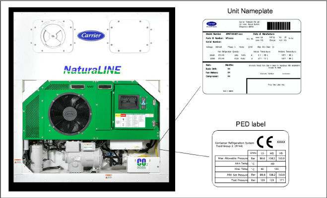
Unit information is provided on a unit nameplate and PED label (see Figure 2.1) located to the right of the compressor, on the side wall next to the Variable Frequency Drive (VFD) section. The nameplate provides the unit model number, serial number and parts identification number (PID). The model number (69NT40-601-XXX) identifies the overall unit configuration, while the PID number provides information on specific optional equipment, factory provisioned to allow for field installation of optional equipment, and differences in detailed parts.
If a problem occurs, please refer to the information on this nameplate and make a note of the model and serial number before calling for assistance. This information will be needed when you contact the technician so that he may properly assist you.
Figure 2.1 Unit Nameplate and PED Label Location
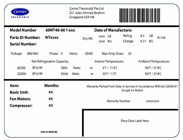
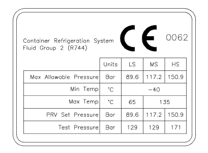
Figure 2.3 PED Label (from PID NT5010)
1.Refrigeration unit is provided by Carrier Transicold. Dimensional outline is available upon request.
2.Installation and material guidelines are the responsibility of the container box manufacturer. Refer to the box manufacturer for final instructions.
Installation: Refrigeration unit must be inserted into the container so that all four flanges contact the container at nearly the same time and no “wrenching” of the unit occurs. Inserting the unit into the container while the unit remains tilted on forks so that one flange of the unit hits hard against the container first can cause serious damage to the unit.
Units are equipped with a control box that may be fitted with a lockable door.
2.4.2Temperature Readout - Refrigerant Temperature
The unit is fitted with a Compressor Discharge Temperature Sensor (CPDS), an Evaporator Temperature Sensor (ETS), and a Gas Cooler Temperature Sensor (GCTS).
2.4.3Temperature Readout - Air Temperature
The unit is fitted with an Ambient Temperature Sensor (AMBS), a Return Temperature Sensor (RTS), a Return Recorder Sensor (RRS), a Supply Temperature Sensor (STS), a Supply Recorder Sensor (SRS), and a Defrost Temperature Sensor (DTS).
The unit is fitted with a Suction Pressure Transducer (SPT), a Flash Tank Pressure Transducer (FPT), and a Discharge Pressure Transducer (DPT).
The unit is fitted with a reciprocating compressor equipped with suction, discharge and mid-stage connections.
2.4.6Gas Cooler / Intercooler Coil
The unit is fitted with a three row Gas Cooler / Intercooler coil using heavy wall tubing.
The Evaporator section contains an evaporator coil and heaters, two three-phase fan motors, and is equipped with an Electronic Expansion Valve (EEV). Opening of an evaporator fan internal protector will shut down the unit.
The unit is fitted with a Flash Tank.
2.4.9Variable Frequency Drive (VFD)
The unit is fitted with a Variable Frequency Drive (VFD).
Units that use the DataCORDER function are fitted with interrogator receptacles for connection of equipment to download the recorded data. Two receptacles may be fitted; one is accessible from the front of the container and the other is mounted inside the container (with the USDA receptacles).
Each unit is equipped with a tethered set of wiring schematics and wiring diagram plates. The plate sets are ordered using a seven-digit base part number and a two-digit dash number.
Various options may be factory or field equipped to the base unit. These options are listed and described in the following sub-paragraphs.
The refrigeration controller may be fitted with standard replaceable batteries or a rechargeable battery pack. Rechargeable battery packs may be fitted in the standard or in a secure location.
The unit may be fitted with a Humidity Sensor (HS). This sensor allows setting of a humidity set point in the controller. In dehumidification mode, the controller will operate to reduce internal container moisture level.
The unit may be supplied with fittings for additional temperature probes, which allow recording of USDA Cold Treatment data by the integral DataCORDER function of the Micro-Link refrigeration controller.
The unit may be fitted with a remote monitoring receptacle. This item allows connection of remote indicators for COOL, DEFROST and IN RANGE. Unless otherwise indicated, the receptacle is mounted at the control box location.
2.5.5Communications Interface Module
The unit may be fitted with a communications interface module. The communications interface module is a slave module, which allows communication with a master central monitoring station. The module will respond to communication and return information over the main power line. Refer to the ship master system technical manual for further information.
The unit may be equipped with handles to facilitate access to stacked containers. These fixed handles are located on either side of the unit.
The unit may be fitted with ports in the front of the frame for insertion of a thermometer to measure supply and/or return air temperature. If fitted, the port(s) will require a cap and chain.
Aluminum back panels may have access doors and/or hinge mounting.
Various power cable and plug designs are available for the main 460 volt supply. The plug options tailor the cables to each customer’s requirements.
Various designs are available for storage of the power cables. These options are variations of the compressor section cable guard.
2.5.11Vent Position Sensor (VPS)
The unit may be fitted with a fresh air makeup assembly, upper or lower. The fresh air makeup assembly is available with a Vent Position Sensor (VPS) and may also be fitted with screens.
Safety instruction and function code listing labels differ, depending on the options installed. Labels available with additional languages are listed in the parts list.
2.5.13Gas Cooler / Intercooler Grille
The Gas Cooler / Intercooler grilles are direct bolted (standard) or hinged (option).