
3.1.1Refrigeration Unit - Front Section
The refrigeration unit is designed so that the majority of components are accessible from the front (see Figure 3.1).
The function of the upper fresh air makeup vent is to provide ventilation for commodities that require fresh air circulation. The venting system / Vent Position Sensor (VPS) is located in the upper left access panel.
Figure 3.1 Refrigeration Unit - Front Section
1)Upper Fresh Air Makeup Vent Panel. Located inside are Evaporator Fan #2, Defrost Temperature Sensor (DTS)
2)Access Panel. Located inside are Evaporator Fan #1, Electronic Expansion Valve (EEV), Heat Termination Thermostat (HTT)
7)Interrogator Connector (Front right)
8)Variable Frequency Drive (VFD)
9)Unit Nameplate: Serial Number, Model Number and Parts Identification Number (PID)
10)Power Cables & Plug location
11)Ambient Temperature Sensor (AMBS)
12)Unloader Solenoid Valve (USV)
17)TIR (Transports Internationaux Routiers) Sealing Provisions - Typical All Panels
- - - - -
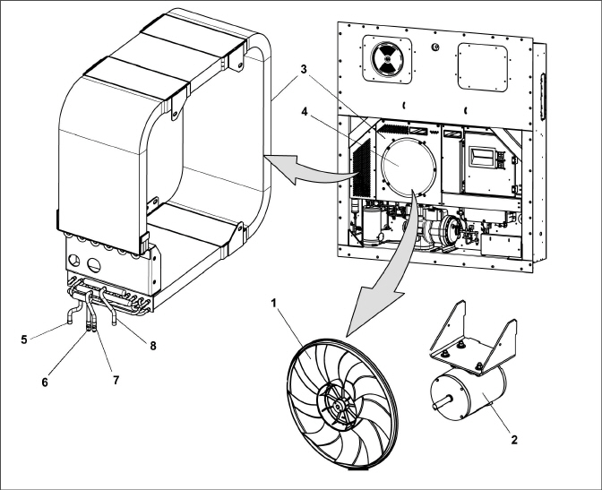
The two evaporator fans circulate air through the container by pulling air in from the top of the unit, directing the air through the evaporator coil where it is cooled or heated, and then discharging the conditioned air at the bottom of the unit.
Most evaporator components are accessible by removing the upper rear panel (as shown in Figure 3.2) or by removing the evaporator fan access panels (see Figure 3.1).
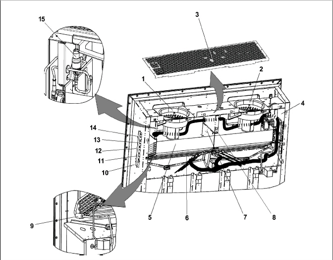
1)Evaporator Fan Motor #1 (EM1)
2)Evaporator Fan Motor #2 (EM2)
3)Return Recorder Sensor (RRS)
Return Temperature Sensor (RTS)
6)Evaporator Coil Heaters (Underside of Coil)
7)Heat Termination Thermostat (HTT)
8)Defrost Temperature Sensor (DTS)
9)Evaporator Temperature Sensor (ETS1)
10)Interrogator Connector (Rear) (ICR)
15)Electronic Expansion Valve (EEV)
- - - - -
3.1.4Compressor and Flash Tank Section
Figure 3.3 Compressor and Flash Tank Section - PIDs lower than NT5010
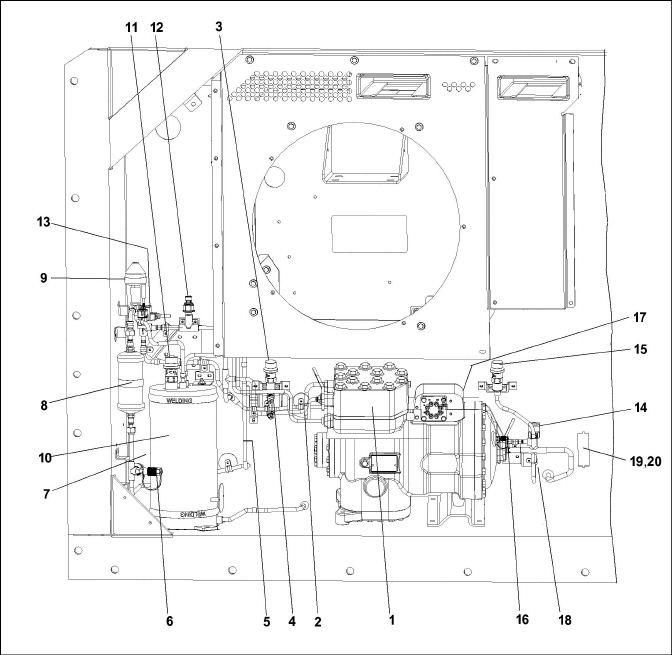
2)Compressor Discharge Temperature Sensor (CPDS)
3)High Pressure Relief Valve (HPRV)
5)Gas Cooler Temperature Sensor (GCTS)
6)High Side Service Connection
7)Discharge Pressure Transducer (DPT)
9)High Pressure Expansion Valve (HPXV)
11)Flash Tank Pressure Relief Valve (FTPRV)
12)Flash Tank Pressure Transducer (FPT)
13)Economizer Solenoid Valve (ESV)
14)Unloader Solenoid Valve (USV)
15)Low Pressure Relief Valve (LPRV)
16)Low Side Service Connection
17)Suction Pressure Transducer (SPT)
18)Ambient Temperature Sensor (AMBS)
19)Supply Recorder Sensor (SRS)
20)Supply Temperature Sensor (STS)
- - - - -
Figure 3.4 Compressor and Flash Tank Section - PIDs NT5010 and higher
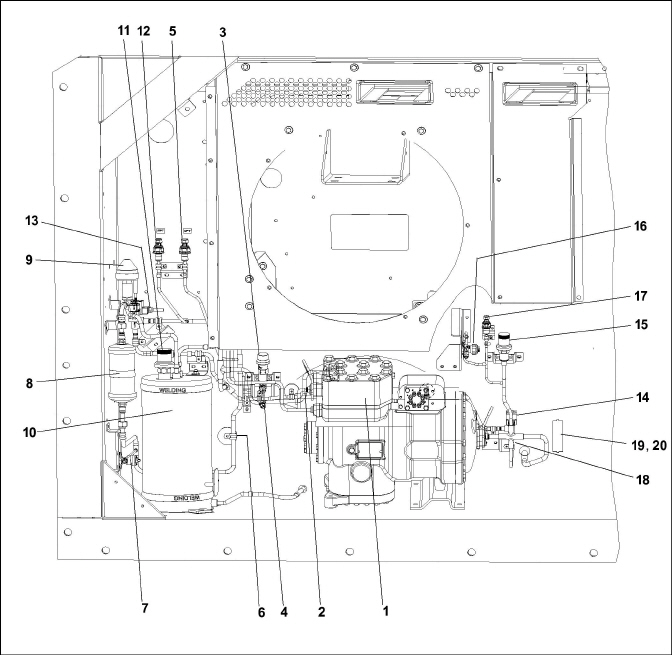
2)Compressor Discharge Temperature Sensor (CPDS)
3)High Pressure Relief Valve (HPRV)
5)Discharge Pressure Transducer (DPT)
6)Gas Cooler Temperature Sensor (GCTS)
7)High Side Service Connection
9)High Pressure Expansion Valve (HPXV)
11)Flash Tank Pressure Relief Valve (FTPRV)
12)Flash Tank Pressure Transducer (FPT)
13)Economizer Solenoid Valve (ESV)
14)Unloader Solenoid Valve (USV)
15)Low Pressure Relief Valve (LPRV)
16)Low Side Service Connection
17)Suction Pressure Transducer (SPT)
18)Ambient Temperature Sensor (AMBS)
19)Supply Recorder Sensor (SRS)
20)Supply Temperature Sensor (STS)
- - - - -
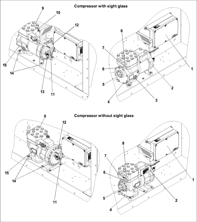
1)Variable Frequency Drive (VFD)
3)Moisture Indicator / Sight Glass (if equipped)
6)First Stage Discharge Port / Flange
7)Second Stage Suction Port / Flange
8)Second Stage Discharge Port / Flange
10)Suction Pressure Transducer (SPT)
13)Service Connection, Suction
15)Compressor Serial / Model Number Plate
- - - - -
The gas cooler / intercooler coil acts as a heat exchanger in which compressed refrigerant gas from the compressor is lowered in temperature as it circulates through the coil tubes. The gas cooler / intercooler fan pulls external, ambient air through all four sides of the coil, heat from the refrigerant is transferred to the air, and then the warm air is discharged horizontally through the front of the fan grille.
Figure 3.6 Gas Cooler / Intercooler
- - - - -
Figure 3.7 Control Box Section
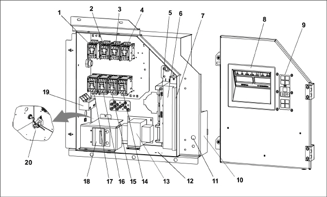
5)Communications Interface Module
6)Controller / DataCORDER Module (Controller)
7)Variable Frequency Interface Module (VIM)
10)Controller Battery Pack standard location
12)Interrogator Connector Box location
14)High Speed Evap. Fan Contactor - EF
15)Low Speed Evap. Fan Contactor - ES
16)High Speed Gas Cooler Fan Contactor - GF
17)Low Speed Gas Cooler Fan Contactor - GS
18)Circuit Breaker (CB-1) - 25 Amps
- - - - -
3.1.7Communications Interface Module
The optional communications interface module (see Figure 3.7) is a slave module that allows communication with a master central monitoring station. The module will respond to communication and return information over the main power line. Refer to the master central monitoring station technical manual for additional information.
3.1.8Water-Cooled Condenser Section
The water-cooled condenser section (Figure 3.8) consists of a water-cooled condenser, water couplings, and a water pressure switch.
Figure 3.8 Water-Cooled Condenser
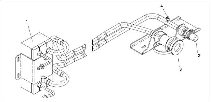
3)Self Draining Coupling (Water Out)
- - - - -
158 kg (348 lb) |
||
Carrier P/N 46-00025-06 Idemitsu FVC 100D |
||
2000 ml (67 ounces) |
||
The oil level range, while the unit operating, should be between 1/4 and 3/4 level of the sight glass. |
||
Variable |
||
Variable |
||
Opens |
54°(+/- 3) C& = 130°(+/- 5) F |
|
Closes |
38°(+/- 4) C = 100°(+/- 7) F |
|
Cut-Out |
138 (+7/-11) bar = 2000 (+100/-156) psig |
|
Cut-In |
99 (+/- 10) bar = 1430 (+/- 140) psig |
|
Charge according to nameplate specifications to ensure optimal unit performance. |
||
Unit Configuration |
Charge Requirements |
|
99.9% pure & CO2 with maximum 10 ppm of water (AHRI 700) |
For
servicing, charge to 9.5 lbs / 4.31kg. |
|
PIDs lower than NT5010 |
||
Opens, Low Side |
89.6 bar = 1300 psig |
|
Opens, Flash Tank |
108.2 bar = 1569 psig |
|
Opens, High Side |
150.9 bar = 2189 psig |
|
PIDs NT5010 and higher |
||
Opens, Low Side |
89.6 bar = 1300 psig |
|
Opens, Flash Tank |
117.2 bar = 1700 psig |
|
Opens High Side |
150.9 bar = 2189 psig |
|
Refer to nameplate, see Figure 2.2 |
||
Cut-In |
0.5 + 0.2 kg/cm3 (7 + 3 psig) |
|
Cut-Out |
1.6 + 0.4 kg/cm3 (22 + 5 psig) |
|
Pressure
Relief Valves
|
PIDs lower than NT5010 |
|
Low Side Pressure Relief Valve (LPRV) |
88.1-96.3 Nm (65-71 ft-lb) |
|
Flash Tank Pressure Relief Valve (FTPRV) |
29.8-32.5 Nm (22-24 ft-lb) |
|
High Side Pressure Relief Valve (HPRV) |
51.5-56.9 Nm (38-42 ft-lb) |
|
PIDs NT5010 and higher |
||
Low Side Pressure Relief Valve (LPRV) |
77.3-85.4 Nm (57-63 ft-lb) |
|
Flash Tank Pressure Relief Valve (FTPRV) |
29.8-32.5 Nm (22-24 ft-lb) |
|
High Side Pressure Relief Valve (HPRV) |
51.5-56.9 Nm (38-42 ft-lb) |
|
Pressure Transducers |
PIDs lower than NT5010 |
|
Suction Pressure Transducer (SPT) |
25.7-28.5 Nm (19-21 ft-lb) |
|
Flash Tank Pressure Transducer (FPT) |
9.5-12.2 Nm (7-8 ft-lb) |
|
Discharge Pressure Transducer (DPT) |
9.5-12.2 Nm (7-8 ft-lb) |
|
Service Fittings / Service Valves |
PIDs lower than NT5010 |
|
Suction Service Fitting |
25.7-28.5 Nm (19-21 ft-lb) |
|
Discharge Service Fitting |
9.5-12.2 Nm (7-8 ft-lb) |
|
PIDs NT5010 and higher |
||
Suction or Discharge Service Valve |
||
Top Cap |
10-14 Nm (7-10 ft-lb) |
|
Stem, Open |
Max. 2 Nm (1.5 ft-lb) |
|
Stem, Closed |
6-8 Nm (4-6 ft-lb) |
|
Flare Cap |
10-14 Nm (7-10 ft-lb) |
|
Filter Drier |
Filter Drier |
18.4-22.1 Nm (25-30 ft-lb) |
Pressure Switch |
High Pressure Switch |
17.6-19 Nm (13-14 ft-lb) |
Bolts |
Compressor Flange Bolts |
35.3-38 Nm (26-28 ft-lb) |
CB-1 |
25 amps |
||
Full Load Amps (FLA) |
13 amps @ 460 VAC |
||
Nominal Supply |
380 VAC, 3 Phase, 50 Hz +/- 2.5% Hz |
460 VAC, 3 Phase, 60 Hz +/- 2.5% Hz |
|
Full Load Amps, High Speed |
1.10 amps |
1.20 amps |
|
Full Load Amps, Low Speed |
0.68 amps |
0.69 amps |
|
Horsepower, High Speed |
0.35 hp |
0.60 hp |
|
Horsepower, Low Speed |
0.04 hp |
0.06 hp |
|
RPM, High Speed |
1450 rpm |
1725 rpm |
|
RPM, Low Speed |
700 rpm |
825 rpm |
|
Voltage |
360 - 460 VAC |
400 - 500 VAC |
|
Bearing Lubrication |
Factory lubricated, additional grease not required. |
||
Rotation |
Counter-clockwise when viewed from shaft end. |
||
Number of Heaters |
6 |
||
Rating |
750 watts +/- 5% each @ 230 VAC |
||
Resistance (cold) |
72 ohms +/- 5% @ 20°C (68°F) |
||
Type |
Sheath |
||
Nominal Supply |
380 VAC, 3 Phase, 50 Hz +/- 2.5% Hz |
460 VAC, 3 Phase, 60 Hz +/- 2.5% Hz |
|
Full Load Amps High Speed |
1.07 |
0.9 |
|
Full Load Amps Low Speed |
0.47 |
0.47 |
|
Nominal Horsepower High Speed |
0.36 |
0.63 |
|
Nominal Horsepower Low Speed |
0.05 |
0.08 |
|
Rotations Per Minute High Speed |
2850 rpm |
3450 rpm |
|
Rotations Per Minute Low Speed |
1425 rpm |
1725 rpm |
|
Voltage |
360 - 460 VAC |
400 - 500 VAC |
|
Bearing Lubrication |
Factory lubricated, additional grease not required |
||
Rotation |
CW when viewed from shaft end |
||
Control Circuit |
7.5 amps (F3A, F3B) |
||
Controller / DataCORDER |
5 amps (F1, F2) |
||
Electrical Output |
0.5 VDC to 4.5 VDC over 90 degree range |
||
Supply Voltage |
5 VDC +/- 10% |
||
Supply Current |
5 mA (typical) |
||
Nominal Resistance @ 20° C (68°F) |
12.4 ohms +/- 5% |
||
Maximum Current Draw |
0.7 amps |
||
Nominal Resistance |
100 ohms A-B and C-D |
||
Supply Voltage |
12 VDC +/- 10% |
||
High Pressure Expansion Valve (HPXV) |
Nominal Resistance |
30 ohms from Ground / Common 1 to 2, 3, 4 and 5 on the KE plug |
|
Supply Voltage |
12 VDC +/- 10% |
||
460 Volts |
Variable Frequency |
||
Orange wire |
Power |
||
Red wire |
Output |
||
Brown wire |
Ground |
||
Input voltage |
5 VDC |
||
Output voltage |
0 to 3.3 VDC |
||
Output voltage readings verses relative humidity (RH) percentage: |
|||
30% |
0.99 V |
||
50% |
1.65 V |
||
70% |
2.31 V |
||
90% |
2.97 V |
||
Controller |
Setpoint Range |
-40 to +30°C (-40 to +86°F) |
|
3.5Safety and Protective Devices
Unit components are protected from damage by safety and protective devices listed in Table 3–1. These devices monitor the unit operating conditions and open a set of electrical contacts when an unsafe condition occurs.
Open safety switch contacts on either or both of devices IP-CP or HPS will shut down the compressor.
Open safety switch contacts on device IP-CM will shut down the Gas Cooler fan motor.
The entire refrigeration unit will shut down if one of the following safety devices open: (a) circuit breaker(s); (b) fuse (F3A / F3B, 7.5A); or (c) evaporator fan motor internal protector(s) - (IP).
The NaturaLINE unit operates as a vapor compression refrigeration system using R-744 (CO2) as the refrigerant. The main components of the system are a Reciprocating Compressor, Gas Cooler/Intercooler, High Pressure Expansion Valve (HPXV), Flash Tank, Electronic Expansion Valve (EEV), Economizer Solenoid Valve (ESV), Unloader Solenoid Valve (USV) and an Evaporator.
The refrigeration system operates in one of three modes; Standard, Unloaded, or Economized. At system start up, and during periods of low refrigeration load, the unit will operate in Unloaded Mode. This allows the microprocessor to place the system in operation at reduced capacity in order to measure the actual load. If the microprocessor determines that further capacity is required, such as periods of high load or pull down, the system will transition to Economized Mode. Standard Mode is used to maintain temperature during stable load conditions.
At the compressor, the CO2 refrigerant is drawn in at the suction port and compressed into a higher pressure, higher temperature gas. The compressed gas exits the first stage of the Compressor, enters the Intercooler, then returns back to the Compressor at the second stage suction port, where the gas is compressed to a higher pressure and higher temperature. The compressed gas then exits the Compressor at the discharge port and flows through the Gas Cooler. Discharge temperature of the refrigerant is continuously monitored by the Compressor Discharge Temperature Sensor (CPDS).
As refrigerant travels through the tubes in the Gas Cooler, ambient air flowing across the coil fins and tubes removes heat from the refrigerant gas. As heat from the refrigerant is transferred to the ambient air, the refrigerant gas cools and then passes through the Filter Drier. The Filter Drier ensures that the refrigerant is clean and dry.
The flow of refrigerant from the Filter Drier to the Flash Tank is regulated by the High Pressure Expansion Valve (HPXV). The HPXV is controlled by the operating software for optimal performance and efficiency. As the microprocessor receives temperature and pressure data, the HPXV stepper motor will open or close in order to control and maintain maximum system efficiency. As refrigerant flows through the variable orifice of the HPXV, the reduced pressure causes the refrigerant to flash (flash gas) while entering the Flash Tank. In the Flash Tank, vapor and liquid are separated.
The liquid refrigerant from the Flash Tank continues through the liquid line to the Electronic Expansion Valve (EEV). The EEV is used to control the superheat of the refrigerant leaving the Evaporator. As the microprocessor receives suction pressure and temperature data, the microprocessor transmits electronic pulses to the EEV stepper motor which opens or closes the variable valve orifice in order to control and maintain proper superheat. Superheat is controlled to ensure that liquid refrigerant never enters the compressor.
The liquid refrigerant flows through the Evaporator, absorbing heat from the return air as the return air flows across the fins and tubes of the Evaporator coil. As the liquid refrigerant in the Evaporator coil absorbs heat, the refrigerant vaporizes, and the vapor flows through the suction port back to the compressor.
3.6.2First Stage Discharge Port & Suction Port
The high pressure, high temperature refrigerant that is discharged from the first stage discharge port flows directly to the Intercooler section of the Gas Cooler / Intercooler. As the refrigerant travels through the tubes in the Intercooler, ambient air flowing across the coil fins and tubes removes heat, cooling but not condensing the gas. The refrigerant leaving the Intercooler flows to three locations: the check valve (where it is stopped), the Unloader Solenoid Valve (USV) (which is normally closed in Standard and Economized Mode), and to the mid-stage suction port where refrigerant returns to the Compressor.
During system start up and periods of low cooling load, the unit will operate in Unloaded Mode to conserve energy. In Unloaded Mode, the normally closed USV opens. While in Unloaded Mode, a portion of the refrigerant leaving the Intercooler is redirected to the suction port, back to the Compressor. The remaining portion of the refrigerant leaving the Intercooler continues to the second stage suction port. To further reduce cooling, the Variable Frequency Drive (VFD) may reduce Compressor speed.
In Economized Mode, the main refrigeration system operates the same as in Standard Mode, except the microprocessor energizes (opens) the Economizer Solenoid Valve (ESV). When the ESV is open, frozen and pull down capacity of the unit is increased by allowing refrigerant vapor to flow from the Flash Tank through the check valve, and to the mid-stage suction port where the refrigerant returns to the Compressor. During Economized Mode, the USV will remained closed.
3.6.5Electronic Expansion Valve (EEV)
The microprocessor controls the superheat of refrigerant leaving the evaporator by opening and closing the variable orifice in the EEV. The microprocessor transmits electronic pulses to the EEV stepper motor, which opens or closes the valve orifice to maintain superheat. EEV control is based on inputs from the Suction Pressure Transducer (SPT) and the Evaporator Temperature Sensor (ETS).
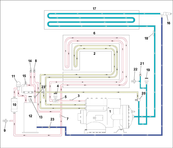
Figure 3.9 Refrigeration Circuit Schematic - PIDs lower than NT5010
3)Compressor Discharge Temperature Sensor (CPDS)
4)High Pressure Relief Valve (HPRV)
5)High Pressure Safety Switch (HPS)
7)Gas Cooler Temperature Sensor (GCTS)
8)Discharge Pressure Transducer (DPT)
11)High Pressure Expansion Valve (HPXV)
13)Flash Tank Pressure Relief Valve (FTPRV)
14)Flash Tank Pressure Transducer (FPT)
15)Economizer Solenoid Valve (ESV)
16)Electronic Expansion Valve (EEV)
18)Evaporator Temperature Sensor (ETS)
19)Low Pressure Relief Valve (LPRV)
20)Unloader Solenoid Valve (USV)
21)Suction Pressure Transducer (SPT), located on back of compressor
- - - - -
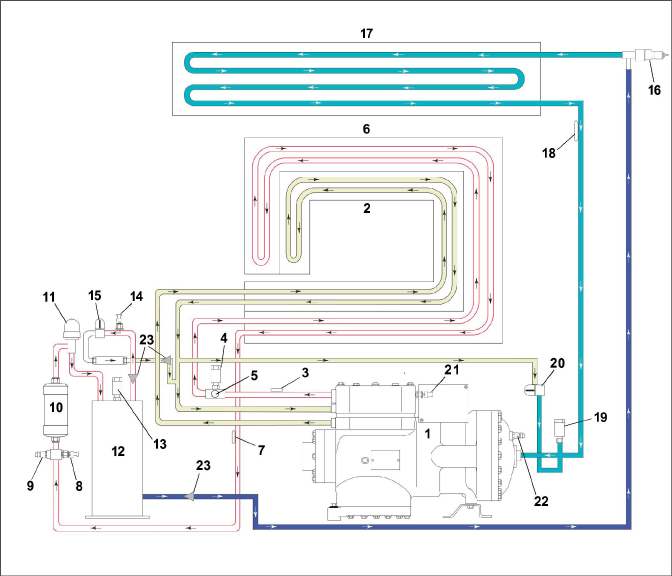
Figure 3.10 Refrigeration Circuit Schematic - PIDs NT5010 and higher
1)Compressor
2)Intercooler
3)Compressor Discharge Temperature Sensor (CPDS)
4)High Pressure Relief Valve (HPRV)
5)High Pressure Safety Switch (HPS)
6)Gas Cooler
7)Gas Cooler Temperature Sensor (GCTS)
8)Discharge Pressure Transducer (DPT)
9)High Side Service Valve
10)Filter Drier
11)High Pressure Expansion Valve (HPXV)
12)Flash Tank
13)Flash Tank Pressure Relief Valve (FTPRV)
14)Flash Tank Pressure Transducer (FPT)
15)Economizer Solenoid Valve (ESV)
16)Electronic Expansion Valve (EEV)
17)Evaporator
18)Evaporator Temperature Sensor (ETS)
19)Low Pressure Relief Valve (LPRV)
20)Unloader Solenoid Valve (USV)
21)Suction Pressure Transducer (SPT)
22)Low Side Service Valve
23)Filter Screens
- - - - -
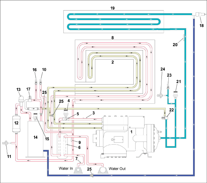
Figure 3.11 Refrigeration Circuit Schematic (WCC) - PIDs lower than NT5010
3)Compressor Discharge Temperature Sensor (CPDS)
4)High Side Pressure Relief Valve (HPRV)
5)High Pressure Safety Switch (HPS)
6)Water Cooled Condenser (WCC)
9)Gas Cooler Temperature Sensor (GCTS)
10)Discharge Pressure Transducer (DPT)
13)High Pressure Expansion Valve (HPXV)
15)Flash Tank Pressure Relief Valve (FTPRV)
16)Flash Tank Pressure Transducer (FPT)
17)Economizer Solenoid Valve (ESV)
18)Electronic Expansion Valve (EEV)
20)Evaporator Temperature Sensor (ETS)
21)Low Side Pressure Relief Valve (LPRV)
22)Unloader Solenoid Valve (USV)
23)Suction Pressure Transducer (SPT)
- - - - -
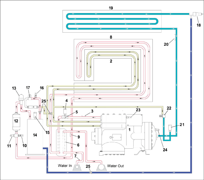
Figure 3.12 Refrigeration Circuit Schematic (WCC) - PIDs NT5010 and higher
1)Compressor
2)Intercooler
3)Compressor Discharge Temperature Sensor (CPDS)
4)High Side Pressure Relief Valve (HPRV)
5)High Pressure Safety Switch (HPS)
6)Water Cooled Condenser (WCC)
7)Water Pressure Switch (WPS)
8)Gas Cooler
9)Gas Cooler Temperature Sensor (GCTS)
10)Discharge Pressure Transducer (DPT)
11)High Side Service Valve
12)Filter Drier
13)High Pressure Expansion Valve (HPXV)
14)Flash Tank
15)Flash Tank Pressure Relief Valve (FTPRV)
16)Flash Tank Pressure Transducer (FPT)
17)Economizer Solenoid Valve (ESV)
18)Electronic Expansion Valve (EEV)
19)Evaporator
20)Evaporator Temperature Sensor (ETS)
21)Low Side Pressure Relief Valve (LPRV)
22)Unloader Solenoid Valve (USV)
23)Suction Pressure Transducer (SPT)
24)Low Side Service Valve
25)Filter Screens
- - - - -