Before servicing the unit, make sure the Start-Stop switch (ST) is in the OFF position. Verify the unit circuit breaker (CB-1) and external power sources are turned OFF and tagged to prevent accidental energizing of circuits.
Potential hazardous atmosphere and low oxygen levels may exist inside the container. Ventilate before entering. Stay away from doors and access panels while venting. See Section 3.7 for venting procedure.
Prior to performing service work, a thorough review and understanding of the entire manual is recommended.
5.1Maintenance Schedule
Table 5–1 Maintenance Schedule
|
Reference Section |
|
|---|---|
| Pre-Trip | |
|
Verify container meets leak specification. |
|
|
Replace poly sheet curtain. |
|
|
Run an “AutCA” to calibrate the O2 sensor and CO2 sensor and check mechanical integrity of components. |
|
| Annually | |
|
Replace the air compressor intake filter. |
|
|
Inspect and clean the water separator. |
|
|
Replace the particulate air filters. |
|
|
Replace the sensor air filter. |
|
|
Check compressor for damage on air compressor coating and repair as needed. Areas affected should be sanded and repainted. |
|
|
Note: Replace a sticker with date when making a filter change. |
|
| 5000 Hours | |
|
Perform minor rebuild of air compressor. |
5.2EverFRESH Air Compressor (EAC) Service
Refer to Warnings in the beginning of this Service section before performing maintenance.
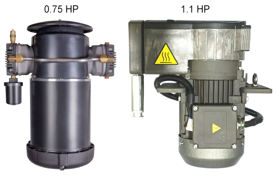
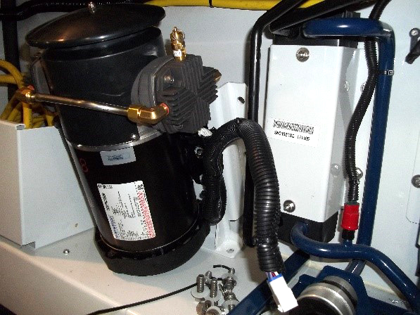
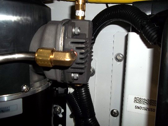
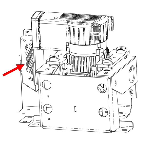
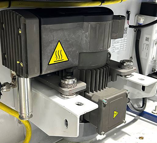
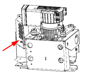
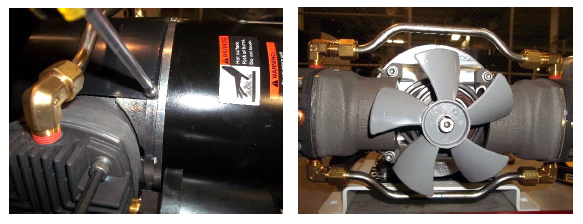
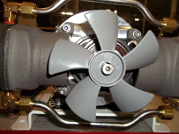
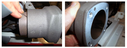
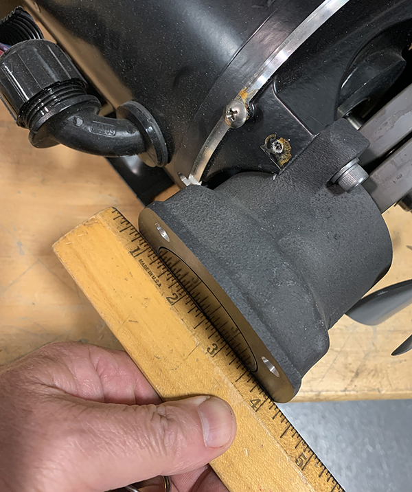
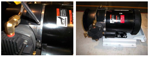
The EverFRESH air compressor is an oil-less, two cylinder compressor mounted on the front of the unit next to the power cord. A unit with EverFRESH will contain either a 0.75 HP air compressor or 1.1 HP air compressor, see Figure 5.1.
Procedures included below for air compressor service are:
•Replacing the air compressor filter
•Replacing the air compressor
•Rebuilding the air compressor (0.75 HP only)
Figure 5.1 Air Compressors - 0.75 HP / 1.1 HP
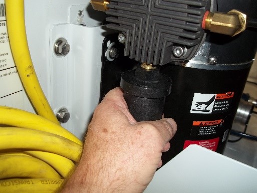
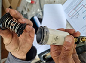
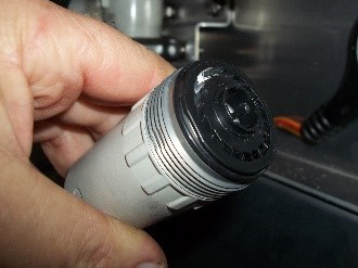
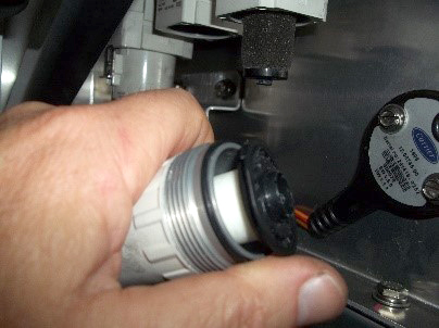
5.2.1Replacing the Air Compressor Filter (0.75 HP Compressor)
1.Rotate the filter housing a 1/4 turn counterclockwise and then pull down.
2.Remove the felt filter.
3.Clean any debris out of the filter housing.
4.Install the new felt filter and then replace the filter cap by pressing up into the slot and turn a 1/4 turn clockwise to lock.
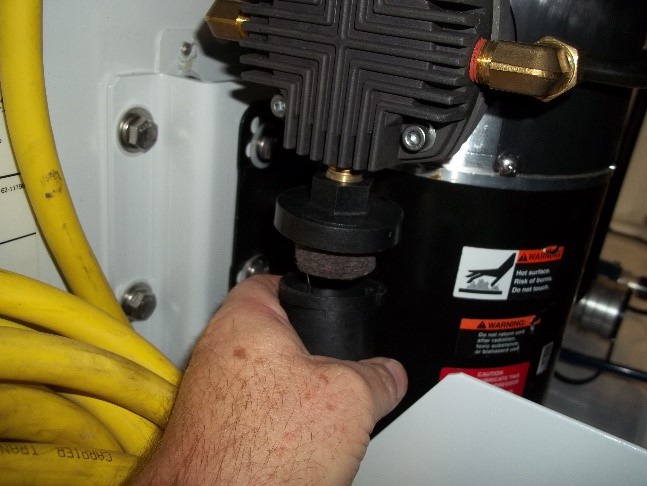
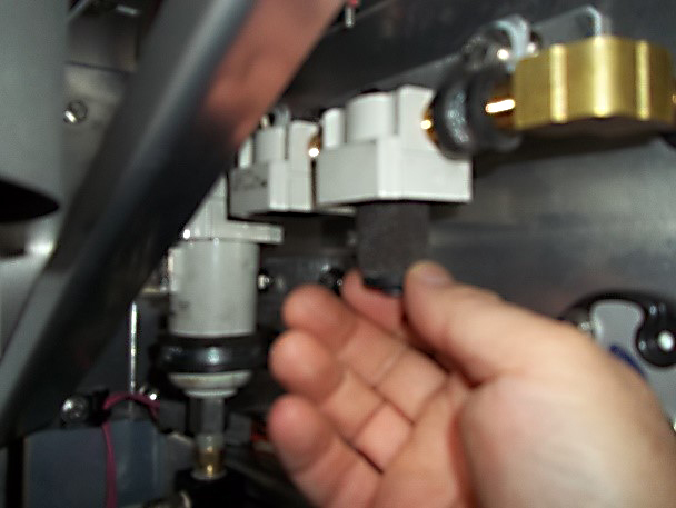
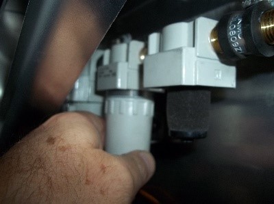
5.2.2Replacing the Air Compressor Filter (1.1 HP Compressor)
1.Pull down on the filter housing to remove it from the slot.
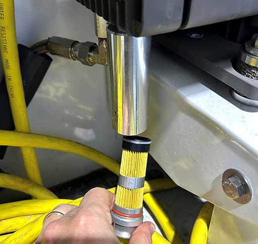
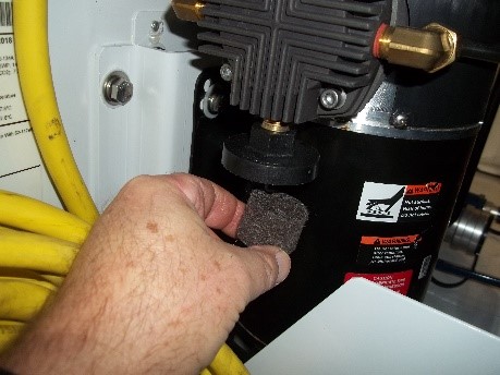
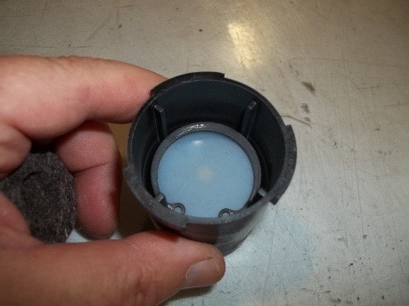
2.Replace the filter media.
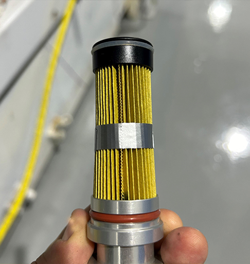
3.Insert the housing back into the slot.
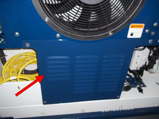
5.2.3Replacing the Air Compressor (0.75 HP Compressor)
Removing the Compressor:
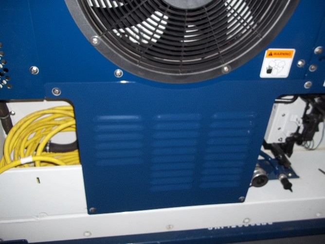
1.Remove the air compressor splash shield by removing the four 1/4” - 20 bolts.
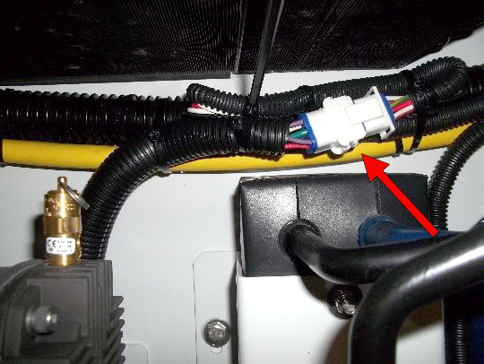
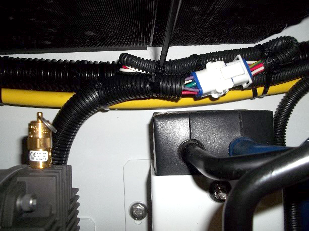
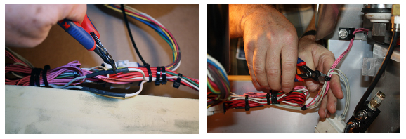
2.Unplug the compressor power connector and cut the wire ties holding the harness in place.
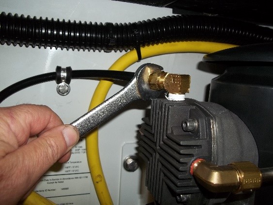
3.Using a 5/8” wrench, remove the air compressor discharge line.
4.Using a 9/16” socket, remove the eight bolts securing the compressor mounting bracket to container frame.
5.Pull the air compressor with the bracket away from the container frame to complete removal.
Installing the Compressor:
1.Place the air compressor with bracket in position and loosely install the upper right hand bolt to hold in place.
2.Install the remaining seven bracket bolts and then torque to 30 to 35 ft-lbs. (41 to 47 Nm).
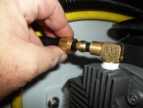
3.Install the discharge line. Tighten with a 5/8” wrench and then torque to 23 in-lbs. (2.6 Nm).
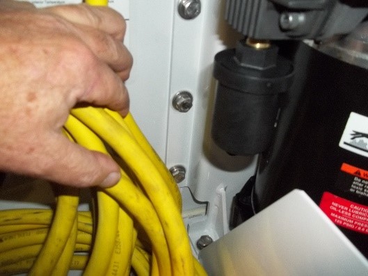
4.Connect the air compressor power connection and wire tie the harness to the drain line and yellow power cable. Maintain a drip loop on the power line prior to entering the compressor motor.
5.Replace the air compressor splash shield. Torque the four bolts to 60 in-lbs. (6.8 Nm).
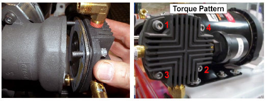
5.2.4Replacing the Air Compressor (1.1 HP Compressor)
Removing the Compressor:
1.Remove the air compressor splash shield by removing the four 1/4” - 20 bolts.
2.Unplug the compressor power connector and cut the wire ties holding the harness in place.
3.Using a 1/4 socket, remove the shield from the left of the compressor.
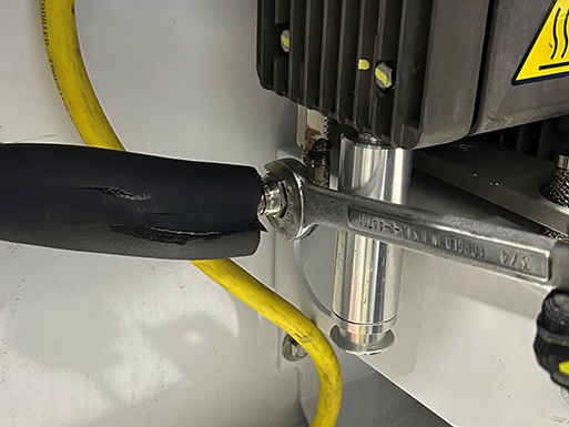
4.Using a 3/4" wrench, remove the air compressor discharge line.
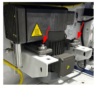
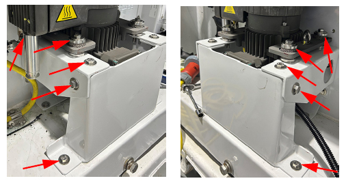
5.Using a 9/16” socket, remove the four mounting bolts from the compressor and six bolts securing the front bracket.
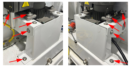
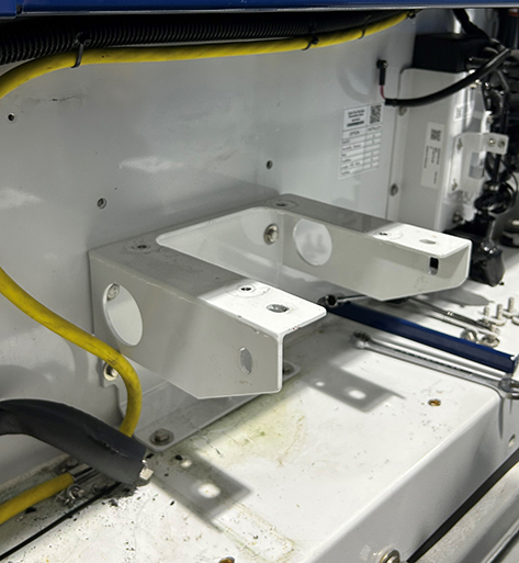
6.Remove the front bracket, compressor and dampers.
Installing the Compressor:
1.Place two bottom halves of damper assemblies on the still attached bracket. Place compressor on the dampers and slide it back. Tilt the compressor back and place two more bottom halves of damper assemblies under the front mounting holes.
2.Install the remaining four pieces of metal cushions + four pieces of cushion seats as shown and align to the holes on the bracket. Tighten the compressor to the bracket with the four saved 2.25" long screws using a 9/16" socket.
3.Insert the front bracket and secure with the six saved 1" long screws using a 9/16" socket.
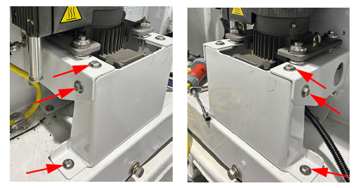
4.Torque all ten bolts to 40 Nm / 354 in-lbs / 29.5 ft-lbs.
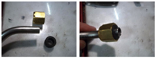
5.Connect the discharge line to the discharge fitting. Hand tighten the nut then tighten with a 3/4" wrench by a further 1/4 turn.
6.Reattach the shield with the four saved 3/4" long screws using a 1/4" socket. Torque to 3.05 Nm / 27 in-lbs.
7.Route and reconnect the compressor power connection.
8.Replace the air compressor splash shield. Torque the four bolts to 60 in-lbs. (6.8 Nm).
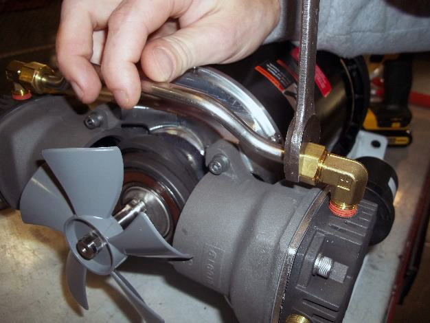
5.2.5Air Compressor Minor Rebuild (0.75 HP Compressor)
Before proceeding with installation, make sure the Start-Stop switch (ST) is in the OFF position. Verify unit circuit breaker (CB-1) and external power sources are turned OFF and tagged to prevent accidental energizing of circuits.
Required Supplies
•Minor Rebuild Kit (part number 18-10185-20)
•Loctite 222 or equivalent
•Torque Wrench capable of 200 in-lbs (22.6 Nm)
•Standard hand tools: 3/16” hex key, 3/4” wrench, phillips screwdriver, gasket removal tool
Procedure for Disassembly:
1.Remove eight phillips screws from the protective shield. Remove the shield. The fan is not part of a minor rebuild so use caution not to damage.
2.Loosen the two crossover pipe compression nuts for one of the heads using a 3/4” wrench.
3.Remove the head with loosened crossbar nuts using a 3/16” hex key. Remove the four head bolts and pull off the head assembly including valve plates. Discard bolts, do not reuse.
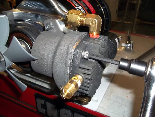
4.Remove crossbars from the air compressor using a 3/4” wrench.
5.Remove the cylinder from the air compressor by removing the 2 - 3/16” hex bolts and pulling off the piston. Use caution not to damage the fan. Discard bolts, do not reuse.
6.Remove the piston guide and rings from the piston.
7.Inspect the piston and cylinder walls for signs of damage, etching in either component. If damage is minor, lightly honing the cylinder is acceptable.
8.Remove the second head and cylinder, inspecting for damage following steps 3, 5, 6 and 7. If all components are satisfactory, complete the minor rebuild by reassembling.
9.Remove the old gasket material from the cylinder head and cylinder using a gasket removal tool. Ensure all parts are clean and free of debris.
1.Install silver rings on the piston first.
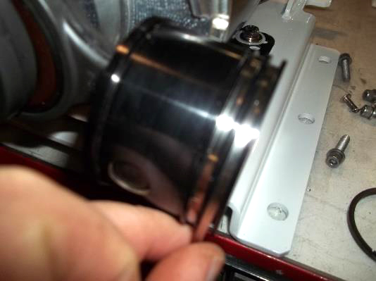
2.Install the black ring over the silver ring on the piston. Open slightly to get over the piston and slide into place. Offset the ring gap by 180 degrees.
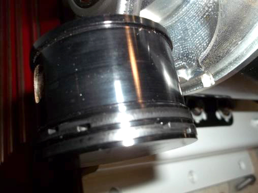
3.Hold the piston rider rings in place and slide the cylinder over the piston. Hold in place with two hex key bolts provided in the kit. Rotate the compressor until the piston is at the top of the cylinder. Position the cylinder so the piston does not go beyond the top of the cylinder. Torque to 150 to 160 in-lbs. (17 to 18 Nm).
Use a straight edge to check that it is flush with the top of the cylinder.
4.Lay the head upside down on a bench. Take the gasket with the material in the middle and place it on the head lettering up and align with the separation in the head and indicator hole.
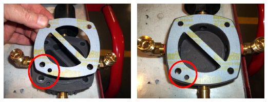
5.Take the outlet valve plate with the line down the center and align with the indicator hole.
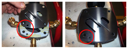
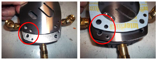
6.Install the new valve plate by aligning the indicator hole on the plate to the discharge valve. When properly installed, two holes will cover the discharge valve and two holes the head is visible. If you cannot see the head on two adjacent holes, the backer plate is not installed properly.
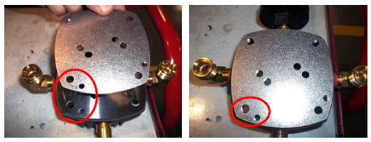
7.Lay the gasket without material in the center on the backer plate. Align the two indicator holes.
8.Place head bolts into two of the holes to maintain alignment of the gaskets and plates and install the head onto the cylinder. Hand tighten the four head bolts. Then rotate the crankshaft to verify the piston does not hit the head. If it doesn’t hit, torque the head bolts to 150 to 160 in-lbs. (17 to 18 Nm) and recheck. If the head does hit, return to step 3 and realign the cylinder.
9.Remove the old compression gaskets on the crossover tubes and replace the compression gaskets. Then install on the first head using a 3/4” wrench. Do not over tighten.
10.On the second head, repeat steps 4 through 8. When installing heads in step 8, ensure crossover pipes are properly seated into the head fittings prior to torquing head bolts. Tighten the crossover compression nuts. Re-torque the cylinder heads to 150 to 160 in-lbs. (17 to 18 Nm).
11.Replace the protective cover. Use thread locker on the eight screws holding the cover in place.
12.Reinstall the air compressor into the system.
13.Run the compressor for 10 minutes by setting the CO2 and O2 setpoints to 5% and turn on the EverFRESH option in Cd71.
14.Shut off the system and unplug main power to the container then re-torque heads to 150 to 160 in-lbs. (17 to 18 Nm).
15.Replace the splash shields.
Refer to Warnings in the beginning of this Service section before performing maintenance.
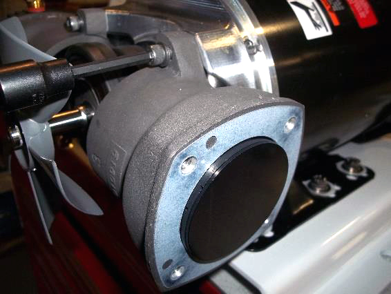
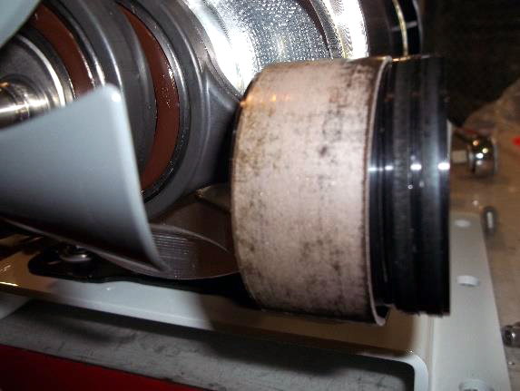
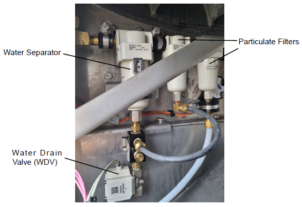
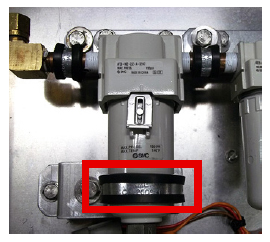
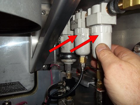
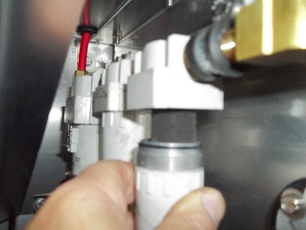
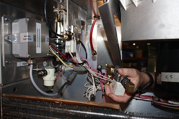
The filter assembly, as shown in Figure 5.2, consists of a water separator and two particulate filters. Any of the condensed moisture will be removed at the water separator. Immediately after the water separator are two particulate filters that removes solid debris from the air stream. The condensate and any solid material that settles to the bottom of the filter assembly is blown out of the line when the Water Drain Valve (WDV) opens.
Figure 5.2 Filter Assembly
5.3.1Removing the Water Separator and Water Drain Valve
1.Open the panel needed to gain access to the water separator, see Figure 5.2. This component can be accessed from the front of the unit through the upper left access panel, or from inside the container through the EverFRESH access panel door.
2.Cut the tie on the Vent Position Sensor (VPS) wiring to relieve tension. Unplug the VPS if installed and remove the access panel.
3.Remove the bolt holding the manifold to the frame, using a 1/4" socket and 11/32" nut driver or wrench.
4.Remove the cushion clamp from the Water Separator bowl.
5.Pull down the locking clamp and turn a 1/4 turn clockwise, and drop the Water Separator bowl.
6.Disconnect the air line and remove the complete assembly.
7.Remove the Water Drain Valve (WDV) from the manifold. Check the inlet for any debris and, if present, collect a sample. Blow out the WDV with shop air and set aside to reinstall after the Water Separator is inspected.
8.Remove the insert from the bowl, inspect the bowl for any foreign materials, wash out the bowl and dry with a clean cloth.
9.If the WDV needs to be replaced, cut the supporting cable ties and cut the wire at the harness splice.
10.Disconnect the WDV by turning it with a 3/4” wrench and using a 9/16” wrench to hold the mating connector.
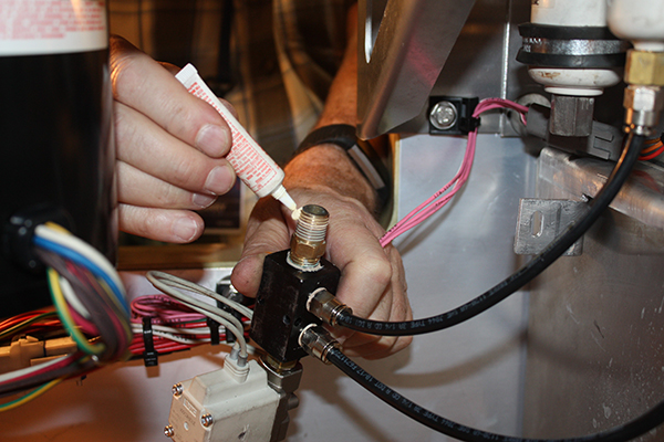
11.To install, follow removal steps in reverse. Make sure to apply a Teflon paste to the brass fitting when re-fitting the WDV to the manifold. Ensure that no Teflon gets into the fitting.
12.Reconnect the VPS apply cable tie and refit the access panel.
5.3.2Replacing the Particulate Air Filters
1.Open the panel needed to gain access to the particulate air filters, see Figure 5.2. This component can be accessed from the front of the unit through the upper left access panel, or from inside the container through the EverFRESH access panel door.
2.Remove both filter housings by turning counterclockwise until free. Carefully lay down each housing to prevent damage to evaporator fins. When removing the second filter housing, it will come off with the housing.
3.Remove the first filter by rotating the filter counterclockwise. Once removed, install the new filter by rotating clockwise.
4.Remove the second filter from the filter housing by pressing up on the locking tab holding the filter in place.
5.Check both filter housings for debris and remove if required. Ensure nothing is blocking the bottom drain on the filter housings.
6.Insert the new filter into the second housing and install the new O-ring on the housing. Prior to installing the O-ring place a thin layer of lubricant around it.
7.Then install the housing back onto the filter body by rotating clockwise until snug.
8.Lubricate the O-ring on the first filter housing and reinstall onto the filter body by rotating clockwise into the base.
Refer to Warnings in the beginning of this Service section before performing maintenance.
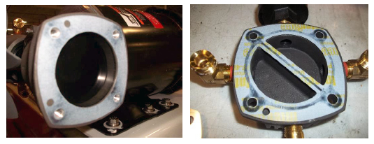
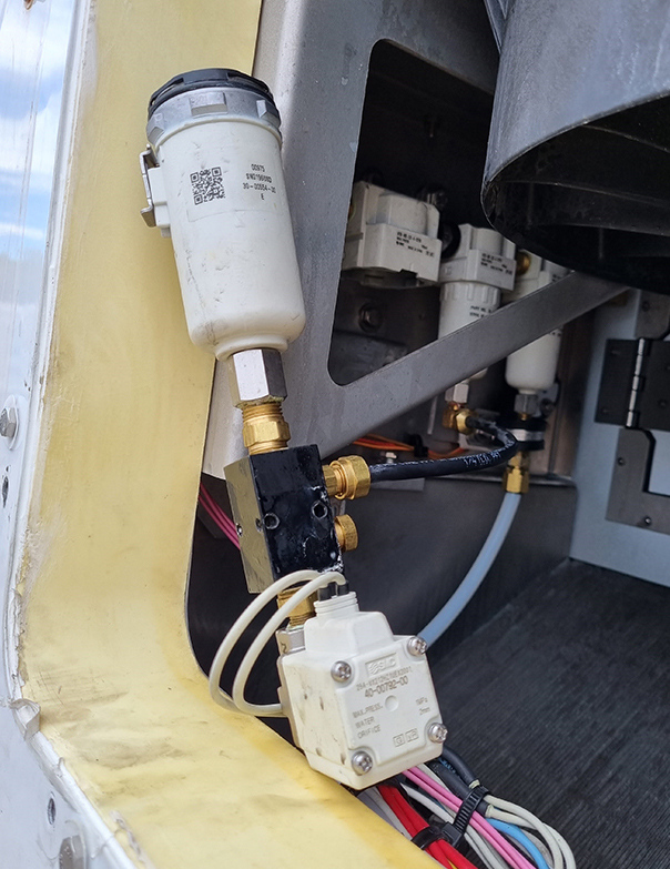
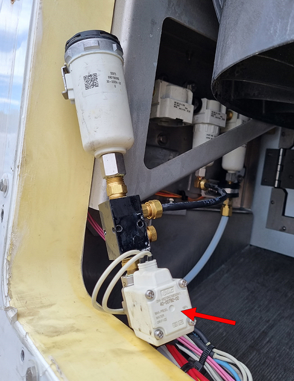
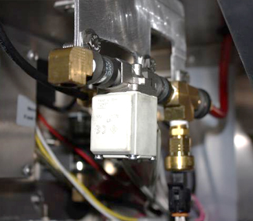
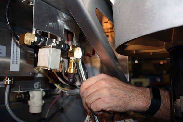
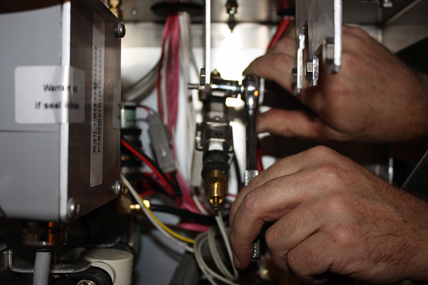
The EverFRESH Air Valve (EA), as shown in Figure 5.3, maintains the desired oxygen levels inside the cargo space. When the controller detects that oxygen levels are dropping below the threshold setting, it will open the EA valve to force the clean, dry, pressurized, air into the cargo space.
Figure 5.3 EverFRESH Air Valve (EA)
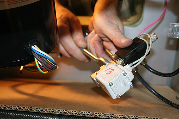
5.4.1Removing the EverFRESH Air Valve
Make note of the direction arrow on the valve body to ensure proper direction of flow.
1.Open the panel needed to gain access to the EverFRESH Air Valve (EA), see Figure 5.3. This component can be accessed from the front of the unit through the upper left access panel, or from inside the container through the EverFRESH access panel door.
2.Place cardboard on the evaporator to protect it from any components or tools that may fall.
3.Disconnect the Membrane Pressure Transducer (MPT) harness.
4.Cut wire ties back to location where coil is spliced into the harness, cut the two lines at the harness crimp, then remove the EA inlet hose using a 9/16” wrench to hold the brass fitting and 5/8” wrench to turn the compression nut. Pull the hose away from the fitting.
5.Remove the three 1/4” x 20 screws with a 7/16” socket and remove the coil assembly.
6.To install, follow the removal steps in reverse.
NOTE: When reinstalling the EA, remove the fittings from the existing valve body and place on the replacement valve body. This is best suited to be completed on a work bench using wrenches. It is not recommended to place the valve body in a vice as it could distort the valve preventing it from functioning properly.
5.5EverFRESH Nitrogen Valve (EN)
Refer to Warnings in the beginning of this Service section before performing maintenance.
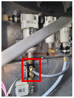
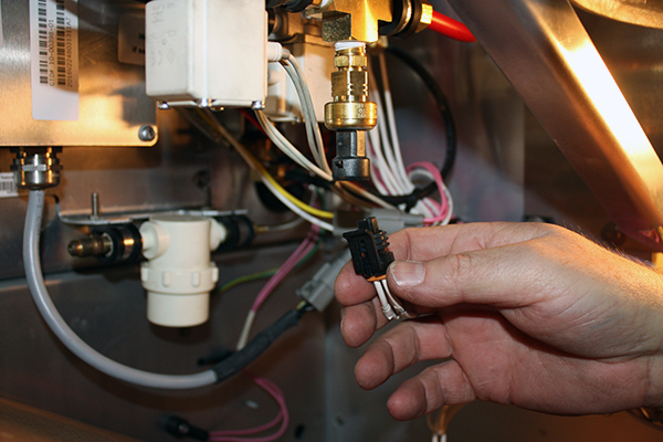
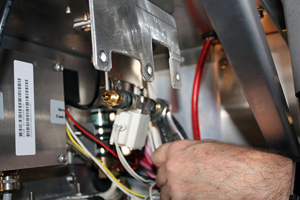
The EverFRESH Nitrogen Valve (EN), as shown in Figure 5.4, opens to allow gas to flow into the sensor package for testing at the O2 sensor.
Figure 5.4 EverFRESH Nitrogen Valve (EN)
5.5.1Removing the EverFRESH Nitrogen Valve
NOTE: Make note of the direction arrow on the valve body to ensure proper direction of flow.
1.Open the panel needed to gain access to the EverFRESH Nitrogen Valve (EN), see Figure 5.4. This component can be accessed from the front of the unit through the upper left access panel, or from inside the container through the EverFRESH access panel door.
2.Place cardboard on the evaporator to protect it from any components or tools that may fall.
3.When removing from the upper left access panel, remove the EA valve assembly first for easier access. Do not cut the wires on the EA coil. Removing the evaporator fan motor will allow for more space but not necessary. When removing from the back of the unit through the EverFRESH access panel, access to the components is easier.
4.Remove the hoses from both sides of the EN.
5.Cut the wire ties holding the EN coil wires to the harness back to where the coil is spliced into the unit. Then, cut the wires at the harness splice.
6.Remove the two 1/4” x 20 screws with a 7/16” socket and remove the coil assembly.
7.Remove the EN from the unit.
8.To install, follow removal steps in reverse.
NOTE: When reinstalling the EN, remove the fittings from the existing valve body and place on the replacement valve body. This is best suited to be completed on a work bench using wrenches. It is not recommended to place the valve body in a vice as it could distort the valve, preventing it from functioning properly.
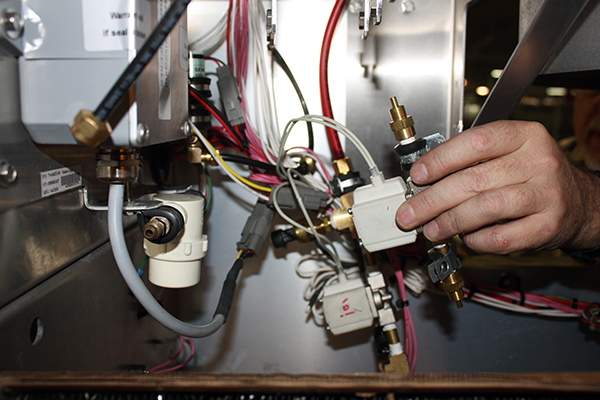
5.6Sensor Assembly
Refer to Warnings in the beginning of this Service section before performing maintenance.
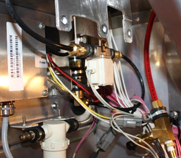
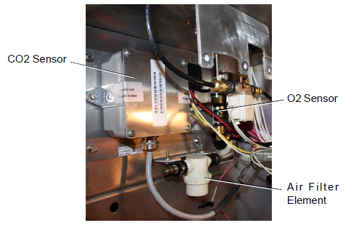
The sensor assembly, as shown in Figure 5.5, consists of an air filter, O2 sensor and CO2 sensor. The O2 sensor monitors O2 levels and allows the system to prevent O2 levels from dropping below the lower setpoint. A CO2 sensor provides CO2 levels to the controller to allow the control algorithm to activate the required EverFRESH components.
Figure 5.5 Sensor Assembly
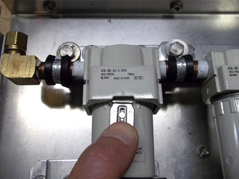
5.6.1Replacing the Sensor Air Filter Element
1.Follow container venting procedures before performing any maintenance on the sensor air filter element. See Section 3.7 for container venting procedure.
2.Open the panel needed to gain access to the sensor air filter element, see Figure 5.5. This component can be accessed from the front of the unit through the upper left access panel, or from inside the container through the EverFRESH access panel door.
3.Unscrew and remove the filter cup from the bottom of the sensor air filter assembly.
4.Remove the filter element from the filter assembly.
5.Install the sensor air filter element by reversing the above steps. Tighten by hand only.
1.Follow container venting procedures before performing any maintenance on the O2 sensor. See Section 3.7 for container venting procedure.
2.Open the panel needed to gain access to the O2 sensor, see Figure 5.5. This component can be accessed from the front of the unit through the upper left access panel, or from inside the container through the EverFRESH access panel door.
3.Remove the cushion clamp and screws that secure the O2 sensor.
4.Cut the wire tie that secures the wiring to the O2 sensor body.
5.Unplug the wiring connector from the receptacle.
6.Remove the O2 sensor from the O2 sensor housing.
7.Install the O2 sensor by reversing the above steps.
8.Perform an “AutCA” procedure to calibrate the oxygen sensor prior to operation. See Section 3.4 for procedure.
1.Follow container venting procedures before performing any maintenance on the CO2 sensor. See Section 3.7 for container venting procedure.
2.Open the panel needed to gain access to the CO2 sensor, see Figure 5.5. This component can be accessed from the front of the unit through the upper left access panel, or from inside the container through the EverFRESH access panel door.
3.Remove the electrical connector and the inlet and outlet tubes from the body of the sensor.
4.Loosen the screws which holds the CO2 sensor to the fan deck bracket.
5.Install replacement CO2 sensor by reversing steps 2 and 3.
6.Perform an “AutCA” procedure to calibrate the CO2 sensor. See Section 3.4 for procedure.
5.7Replacing the EverFRESH Condensing Loop
Refer to Warnings in the beginning of this Service section before performing maintenance.
1.Remove the back panel from the container unit.
2.Remove the rivets holding the return air deck in place.
3.Use a 11/16” and 13/16” wrench to remove the fittings on both ends of the condensing loop.
4.Cut the wire ties holding the condensing loop to the return air grill and remove the condensing loop.
5.Install in reverse: Use a 11/16” and 13/16” wrench to connect the condensing loop to the system piping.
6.Wire tie the condensing loop to the return air grille. Place a wire tie every 10 inches.
7.Replace the rivets in the return air deck.
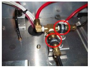
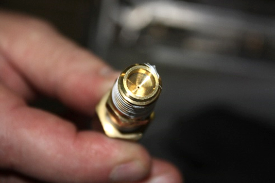
5.8Identifying and Replacing Orifices
The EverFRESH system has two orifices: nitrogen supply and nitrogen sampling, see Figure 5.6, located above the fan deck between the evaporator fan motors.
See Figure 2.3 for location of the orifices in relation to all of the EverFRESH components.
Refer to Warnings in the beginning of this Service section before performing maintenance.
Figure 5.6 Nitrogen Supply and Nitrogen Sampling Orifices
1.For a loaded unit, remove the left hand Evaporator Fan access panel.
For an empty unit, remove the interior upper panel.
2.Remove the left hand Evaporator Fan motor.
3.Remove the two clamps holding the nitrogen distribution block and move the block across to the opening where the fan motor was.
4.Disconnect the nitrogen lines and remove the distribution block.
5.The orifices can now be removed from the distribution block and cleaned or replaced as necessary.
6.Reverse the above steps to re-install the orifices. The orifice end of the connector faces away from the Tee when being re-installed.