EverFRESH and Container Pre-Trip Preparation
6.1Pre-Trip System Preparation
These instructions are provided for proper setup of the EverFRESH system prior to loading with cargo for controlled atmosphere loads. These instructions do not include box preparation.
Before proceeding with preparations, make sure the Start-Stop switch (ST) is in the OFF position. Verify unit circuit breaker (CB-1) and external power sources are turned OFF and tagged to prevent accidental energizing of circuits.
NOTE: This procedure is for Pre-Trip Inspection on a container that is empty and fully vented.
|
Procedure |
|
|---|---|
|
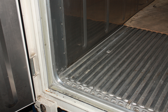
Check container for structural damage / clean T-bars of debris. |
|
|
Ensure floor drains are sealed. |
|
|
Ensure drain hose from evaporator section is not damaged. |
|
|
Ensure drain hose from evaporator section is filled with water. |
|
|
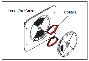
Ensure manual fresh air panel is equipped with collars (réf. 79-04064-00). |
|
|
Ensure manual fresh air panel Multilingual label is in place. |
|
|
Tighten access panel bolts to 60 inch-lbs. |
|
|
Load latest Container software version (6315 or greater). |
|
|
Verify EverFRESH option is enabled via code Cd71. |
|
|
Verify EverFRESH is operational via “AutCA” under PreTrip menu. |
|
|
Leak test box and ensure it meets leak specifications. See procedure below. |
|
|
Leak Test result ____________ minutes |
|
|
Select the desired CO2 and O2 levels via Code Cd71. |
6.2Container Preparation
Check the rear container doors and door handles for proper operating condition. Check for proper installation of labels on the container and refrigeration unit. Always visually check the inside of the container for occupants prior to closing the doors.
6.2.1Box Checkout / Leak Test
When using the EverFRESH system, the box must conform to leak rates in order to maintain control of the O2 and CO2 setpoints. The minimal box requirement is a pressure decay of 2 inch WG (50mm) to 1 inch WG (25mm) of four minutes or more for a 40 foot container. It is recommended that it be checked prior to the voyage.
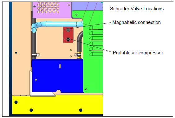
To perform this check, some units may be equipped with two pressure connection ports on the front of the unit, see Figure 6.1. One of the ports is connected to a pressurized air supply and the other is connected to a Magnehelic pressure gauge. The pressure gauge monitors the container leakage rate.
Figure 6.1 Pressure Connection Ports
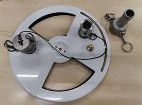
If the ports are not available, then a Manual Fresh Air panel disc assembly (part # 79-04098-03) with two charging ports should be installed, see Figure 6.2.
Figure 6.2 Disc Assembly (79-04098-03) with Charging Ports
Prior to performing the leak test:
•Seal the floor drains with plugs.
•Ensure the unit condensate drain line is filled with water.
•Ensure the manual fresh air vent panel is tightly closed.
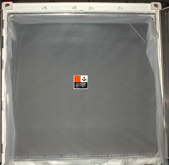
•Insert a plug in the drain hose. Install the container curtain at the rear door.
•Seal the door shut.
Install the door curtain (part number 76-50036-01) into the curtain track installed in the rear of the container. For instructions, see Section 6.3. Always use a new curtain as a small rip in the curtain can result in a test failure.
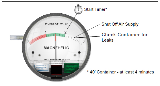
After connecting the gauges, turn on the air supply and regulate the air pressure to 40-60 psi. When the Magnehelic gauge, see Figure 6.3, reads 2.5 inches of water gauge, shut off the air supply. Do not exceed 3.5 inches of WG.
Monitor the Magnehelic pressure gauge for the drop in air pressure in the container. When the Magnehelic pressure gauge reads 2 inches, start a timer. When the Magnehelic pressure gauge reads 1 inch of WG, stop timing. The amount of time expired should be no less than four minutes or more for a 40 foot container. If it is less than the required time, then the container needs to be checked for leaks. Re-pressurize the box to 2.5” WG and spray potential leak areas with soapy water and seal leaks. Note the typical external and internal leak areas to check as described in the following paragraphs.
Figure 6.3 Magnehelic Gauge (Kit # 07-00177-20)
Check for leaks with the following recommended checks. Re-pressurize the container to 2 inches water gauge and look for leaks at the following areas using soapy water (mixture of dish detergent and water) looking for bubbles.
•Inspect the evaporator unit access panels. Check that gasket is properly in place. Tighten the access panel bolts to 60 inch-lbs. and caulk if necessary.
•Inspect the defrost drain outlet line. If it is leaking, complete other checks and re-inspect internally.
•Inspect the unit / container box joints. Caulk if necessary.
•Inspect the through-wire bulkhead connections. Secure and caulk if required.
•Inspect the container floor drains under the container (if accessible). If leaking is observed, complete external checks and reinspect internally.
•Inspect the rear door seals. Ensure the curtain is properly installed (curtain should be visible throughout the perimeter of the doors if installed without a curtain track). Remove and install a new curtain. De-pressurize the container prior to opening the container.
•Ensure Manual Fresh Air Panel is equipped with collars (part number 79-04064-01), see Figure 6.4.
Figure 6.4 Fresh Air Panel Collars
Remove pressure within the container and perform the inspections listed below. On completion of the checks and any associated repairs, it is recommended to test the unit again to verify it now meets the required level.
•Inspect the curtain for any rips. Replace the curtain.
•Inspect the container floor drains. Ensure they are properly sealed. Standard drains can not be used.
•Inspect the defrost drain outlet line. Confirm the drain line is filled with water.
•Inspect for any internal wall damage. Repair and caulk as required
•Inspect floor to side wall joint, floor to front bulkhead joint for any damage. Repair and caulk as required
6.3Container Curtain
Potential hazardous atmosphere and low oxygen levels may exist inside the container. Ventilate before entering. Stay away from doors and access panels while venting. Refer to Section 3.7 for venting procedure.
•CA Curtain Wedge Tool (pack of 5: 07-00573-00PK5)
•Curtain Clips (pack of 50: 34-50093-01)
•Sharp Hand Cutting Tool (purchase locally)
NOTE: Contact your local CAP representative for quantities.
•Curtain (58-04153-02)
•Ribbon Seal (58-66775-00)
•Warning label (69NT--35--1618)
•Instructions (62-11921-00)
1.Open the rear doors of the container box and inspect the curtain track for dirt or damage (edges on track). Clean dirt and remove any sharp edges found on the track.
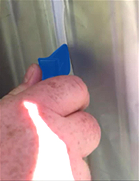
2.Fully unfold the door curtain. Align the arrow with the “CENTER” at the midpoint of the door opening (Figure 2a). Ensure “CENTER” can be read as this is the outside of the curtain.
![]()
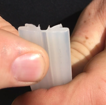
The flat side of the ribbon is pressed into the track.
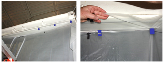
3.Use retaining clips to align the polysheet curtain line on the curtain into the track across the top of the container. Using the line will keep the curtain square.
4.Unroll the curtain ribbon and mark the mid-point.
5.At the midpoint of the ribbon, insert the curtain ribbon into the ribbon channel at the “CENTER” arrow on the curtain.
6.Press the ribbon into the back of the curtain track and seat the front of the ribbon into the track by pushing on the outer edge of the track.
NOTE: Use care when removing the retaining clips to avoid damaging (tearing) the curtain.
7.Insert the curtain into the side channels and across the bottom rail using the retaining clips as required. Make sure the curtain is stretched tight across the opening. Eliminate any folds or wrinkles that can lead to air leakage.
8.Use the Ribbon install tool to finish inserting the curtain ribbon.
9.Repeat steps 3 - 8 on the other side of the door.
10.At the ribbon mating point overlap, by approximately 6 inches (15 cm) and carefully cutoff the excess ribbon allowing for the overlap. Make sure that the ribbon is completely inserted and the curtain is secure.
11.Place warning label on the outside of the curtain.