3.1Introduction
This section addresses the operating requirements for the EverFRESH® controlled atmosphere option. Operating parameters are not changed except for EverFRESH settings. For information pertaining to the operation of the refrigeration system, refer to the Operation and Service Manual for your particular model.
The EverFRESH option offers enhanced functionality to help slow the ripening process of perishable cargo by controlling carbon dioxide (CO2) and oxygen (O2) levels to specified setpoints. This enables the fresh transport of perishables on longer voyages. The system controls the container atmosphere with a nitrogen membrane, a fresh air solenoid and an optional CO2 injection kit.
During the nitrogen control mode, CO2 and O2 are replaced with nitrogen proportionally. EverFRESH also utilizes the cargo’s natural respiration to control CO2 and O2 levels. Additionally, opening and closing a fresh air valve allows for raising O2 levels and controlling CO2 for high respiring cargos. An O2 sensor monitors O2 levels and allows the system to prevent O2 levels from dropping below the lower setpoint. A CO2 sensor provides CO2 levels to the controller to allow the control algorithm to activate the required EverFRESH components. For low respiring cargoes requiring high CO2 setpoints, an optional CO2 Injection system can be used to maintain CO2 levels.
NOTE: While the EverFRESH option is operating, the process of removing ethylene needs to be performed with an external ethylene scrubber (part # 30-50344-00).
The EverFRESH system, as shown in Figure 3.1, utilizes an EverFRESH air compressor (EAC) mounted under the condenser fan to increase the air pressure inside the system. The warm, moisture-laden air exits the compressor, is brought inside the refrigerated space and passes through a condensing loop, consisting of a single piece of copper tubing located above the fan deck. As the compressed air is exposed to the cooler temperature of the cargo space, moisture condenses and is carried to the filter assembly.
The filter assembly consists of a water separator and two particulate filters. Any condensed moisture is first removed at the water separator and then at the first of two particulate filters, to remove debris and any additional moisture. Any condensate and solid material settles to the bottom of the filter assembly and is blown out of the line when the water drain valve (WDV) opens. The water drips onto the evaporator coil and down the defrost drain line. The WDV energizes during the initial unit startup when the air compressor starts. It also opens periodically during air compressor operation to remove accumulated condensate and again before the air compressor is disengaged. The compressed air then passes through a second particulate filter to drain any remaining moisture from the system through the EverFRESH air valve (EA) solenoid. This opens after the WDV operates for draining moisture and when fresh air is required in the system.
The EA maintains the desired oxygen levels inside the cargo space. When the controller detects that oxygen levels are dropping below the threshold setting, it opens the EA valve to force clean, dry, pressurized, air into the cargo space. Since this air contains 21% oxygen, it increases the concentration of oxygen available for respiration. Located before the EA is the membrane pressure transducer (MPT) where the controller monitors system pressure and can determine if the nitrogen membrane separator is maintaining good flow. When the EA is closed, the clean, dry air exits the particulate filter and enters the bottom of the nitrogen membrane separator.
Inside the separator, the air enters thousands of tiny hollow fibers. The smaller, faster molecules of oxygen and carbon dioxide pass through the walls of the membrane fibers, exit the separator through a port on the side, and then are exhausted out the front of the refrigeration unit to the atmosphere. The larger, slower nitrogen molecules stay trapped in the fibers until they exit the top of the separator.
As the nitrogen leaves the separator, it is piped above the fan deck to the nitrogen orifices. The nitrogen supply orifice regulates nitrogen flow out to the air stream, where the evaporator fans blow it across the evaporator and down into the t-slots to enter the cargo space. The nitrogen sampling orifice regulates nitrogen flow to the EverFRESH nitrogen valve (EN).
The controller opens EN to allow the gas to flow into the sensor package for testing at the O2 sensor. Elevated amounts of oxygen indicate the nitrogen membrane may be clogged. The EN is only energized during Pre-trip test P20-5 N2 Check. Otherwise, when the EN is closed during normal operation, gas is forced out of the nitrogen supply orifice. After having the oxygen level tested, the nitrogen flows through the CO2 sensor and is then exhausted back into the cargo air stream above the fan deck.
On systems equipped with a CO2 injection option, the CO2 injection valve (CSV) will control to the CO2 setpoint. As CO2 levels drop below the setpoint, the CSV will open to raise CO2 levels.
Figure 3.1 EverFRESH Air and Gas Flow Diagram
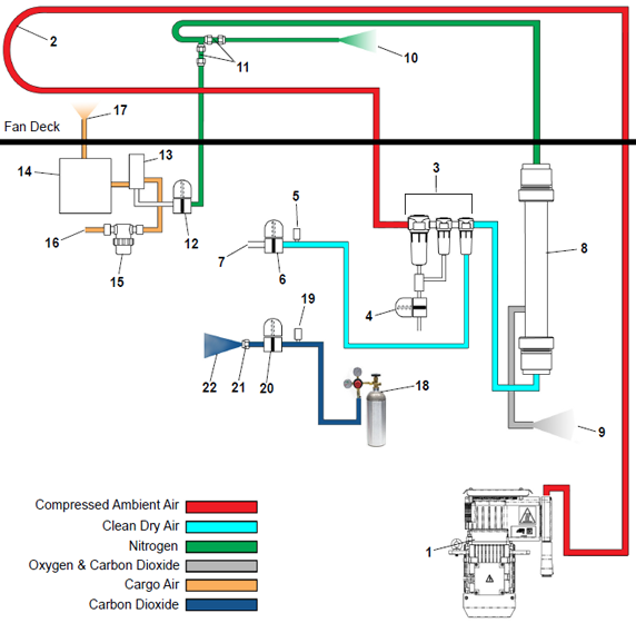
1)Air Compressor
2)Condensing Loop
3)Water Separator & Particulate Filters
4)Water Drain Valve (WDV)
5)Membrane Pressure Transducer (MPT)
6)EverFRESH Air Valve (EA)
7)Fresh Air Supply to Cargo Space
8)Nitrogen Membrane Separator
9)O2 and CO2 Sent to Ambient
10)Nitrogen Supply to Cargo Space
11)Nitrogen Orifices (Supply and Sampling
12)EverFRESH Nitrogen Valve (EN)
13)O2 Sensor
14)CO2 Sensor
15)Sensor Filter Assembly
16)Cargo Air Sensor Inlet
17)Cargo Air Sensor Outlet
18)CO2 Injection Bottle (not included with equipment)
19)CO2 Injection Pressure Transducer (IPT)
20)CO2 Injection Valve (CSV)
21)CO2 Supply Orifice Cap
22)CO2 Supply to Cargo Space
- - - - -
3.4Pre-Trip Inspection
An EverFRESH Pre-Trip Inspection (PTI) is required to run prior to cargo being loaded in order to test operation of mechanical components and calibrate the sensors.
NOTE: Before running a PTI, verify that the container box is well vented.
NOTE: It is not recommended to run a PTI after a frozen condition, including AUtO2.
There are two PTI test sequences that can be run:
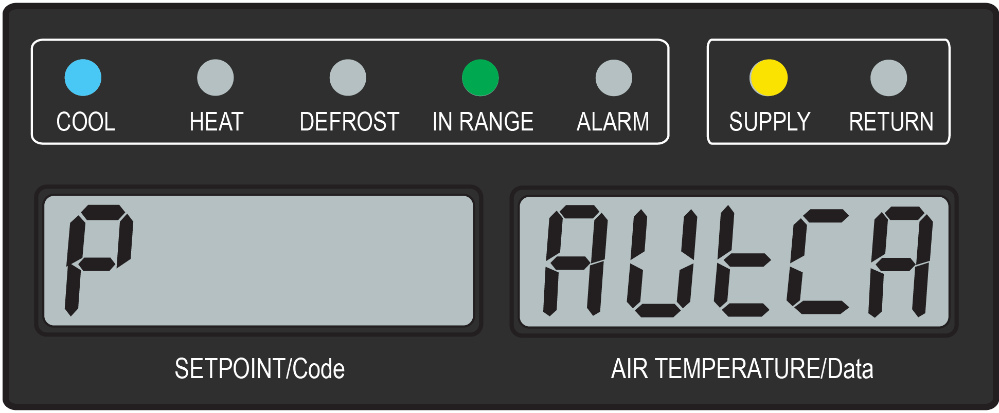
•“P” “AUtCA” initiates a test of all P20 codes: P20-0 through P20-5. This includes P20-4 sensor calibration.
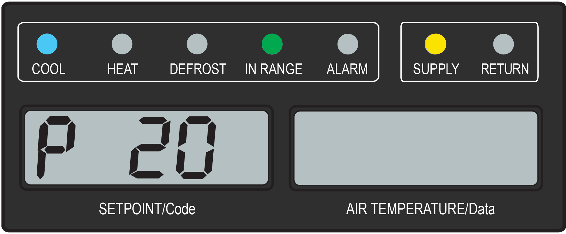
•“P20” initiates a test of codes P20-0 through P20-3 and P20-5, but test P20-4 sensor calibration is skipped.
•If the unit is equipped with CO2 injection, the PTI test sequences will also perform tests P20-6 and P20-7.
3.4.1Initiating a PTI of EverFRESH Components
Prior to performing a PTI, perform system maintenance checks as described in PTI Preparation, see Section 6.1.
1.Press the PRE-TRIP key to access the Pre-trip selection menu.
2.To run the test of all components and sensor calibration, use the Arrow keys to display “P” “AUtCA” and then press the ENTER key.
When the test has completed, the display will show “AUtCA” “End”. Press the ENTER key to resume normal operations.
3.To run the test of all components only, use the Arrow keys to display “P20” then press the ENTER key.
When the test has completed, normal operations resume automatically.
3.4.2PTI Individual Test Codes
When testing components and troubleshooting the system, selecting "P20" from inside the Pre-Trip menu will initiate testing of only EverFRESH components. Sensor calibration will be skipped. These P-20 tests are described below. They will occur in order and will run as a sequence. Current readings for the EverFRESH air compressor (EAC) contactor and solenoid valves are taken internally on the ML5 controller.
NOTE: Tests P20-6 and P20-7 are only run if CO2 injection is installed as an option.
Component acronyms referenced in the below P20 descriptions are: Membrane Pressure Transducer (MPT), EverFRESH Air Compressor (EAC), Water Drain Valve (WDV), EverFRESH Air Valve (EA), and EverFRESH Nitrogen Valve (EN).
P20-0 Membrane Pressure Transducer (MPT) Test
Test Sequence: Test initiates with all EverFRESH and refrigeration machinery off.
Pass Criteria: Validate the MPT. Verifies the sensor is not in alarm status and reading -5 to 5 psig.
P20-1 EverFRESH Air Compressor (EAC) Test
Test Sequence: Start the EAC, open the WDV and run for 10 seconds. Close the WDV and run up to 5 minutes or until pressure reaches 60 PSIG.
Pass Criteria: EAC Current draw > 1.0 amps, MPT in range 60 to 135 PSIG, EAC contactor current in range 350 to 760 mA.
P20-2 EverFRESH Air Valve (EA) Solenoid Test
Test Sequence: EAC continues running from the previous test. Record the MPT. Open the EA for 5 seconds. Record the MPT. Shut off the EAC, wait 5 seconds and close the EA.
Pass Criteria: MPT pressure change > 40 PSI when the EA opens. EA current between 100 and 200mA.
P20-3 Water Drain Valve (WDV) Solenoid Test
Test Sequence: Energize the EAC and allow the system to run up to 5 minutes to build pressure. Record the MPT. Open the WDV and record the pressure. Shut down the EAC. Wait 5 seconds, then check the WDV current. At the end of the test, close the WDV.
Pass Criteria: MPT pressure change > 40 PSI when the WDV opens. WDV current is between 100 and 200mA.
P20-4 CO2 and O2 Sensor Calibration
NOTE: This calibration is only run when AutCA selected. This is skipped if P20 selected.
Test Sequence: “CAL” will be displayed on the left display and a 10-minute countdown timer is displayed on the right display. The unit will run the high speed evaporator fans.
Pass Criteria: The CO2 sensor and O2 sensor will perform an auto calibration provided the sensor signal is valid and values are consistent with ambient air.
Error messages when calibration fails:
The CO2 sensor will be validated and then needs to read between 0.9 and 1.15 VDC to ensure fresh air is present in the sensor prior to calibration. If the level is not reached, “NoCAL” will be displayed.
If CO2 or O2 calibration fails, “O2 Fail” or “CO2 Fail” will be displayed and the test will stop.
The O2 sensor will be validated to verify it is within a specific range suitable for calibration. If voltage is outside of this range, “O2 Fail” will be displayed.
During calibration, the stability of the sensor will be monitored and must be within 20mV over one minute to ensure the sensing chamber is properly flushed with fresh air. If it’s not stable, “NoCAL” will be displayed.
In the event of a “NoCAL”, it indicates that fresh air is not going through the sensors. Verify there is no cargo in the contained space, the sensor filter is not clogged and sensor hoses are properly connected. Then re-run the Pre-trip “AutCA” test under the PRE-TRIP key menu.
P20-5 EverFRESH Nitrogen Valve (EN) Solenoid Test
Test Sequence: Test will start with EAC off. Energize EN and wait 5 seconds. Energize EAC. Test will run up to an additional 300 seconds or until N2 reaches acceptable limit. Then the EAC and EN will be de-energized.
Pass Criteria: EN current is between 100 and 200mA. N2 concentration is at minimum acceptable level.
P20-6 CO2 Injection Valve Solenoid (CSV)
Test Sequence: Open the CSV and wait 5 seconds. Record CSV current.
Pass Criteria: CSV current is between 100 and 200 mA.
P20-7 CO2 Injection Pressure Transducer (IPT)
Test Sequence: Shut off all machinery outputs. Validate the IPT is present. Validate the IPT at 0.0 PSIG.
Pass Criteria: Validate that the IPT reads between -5 and 5 PSIG.
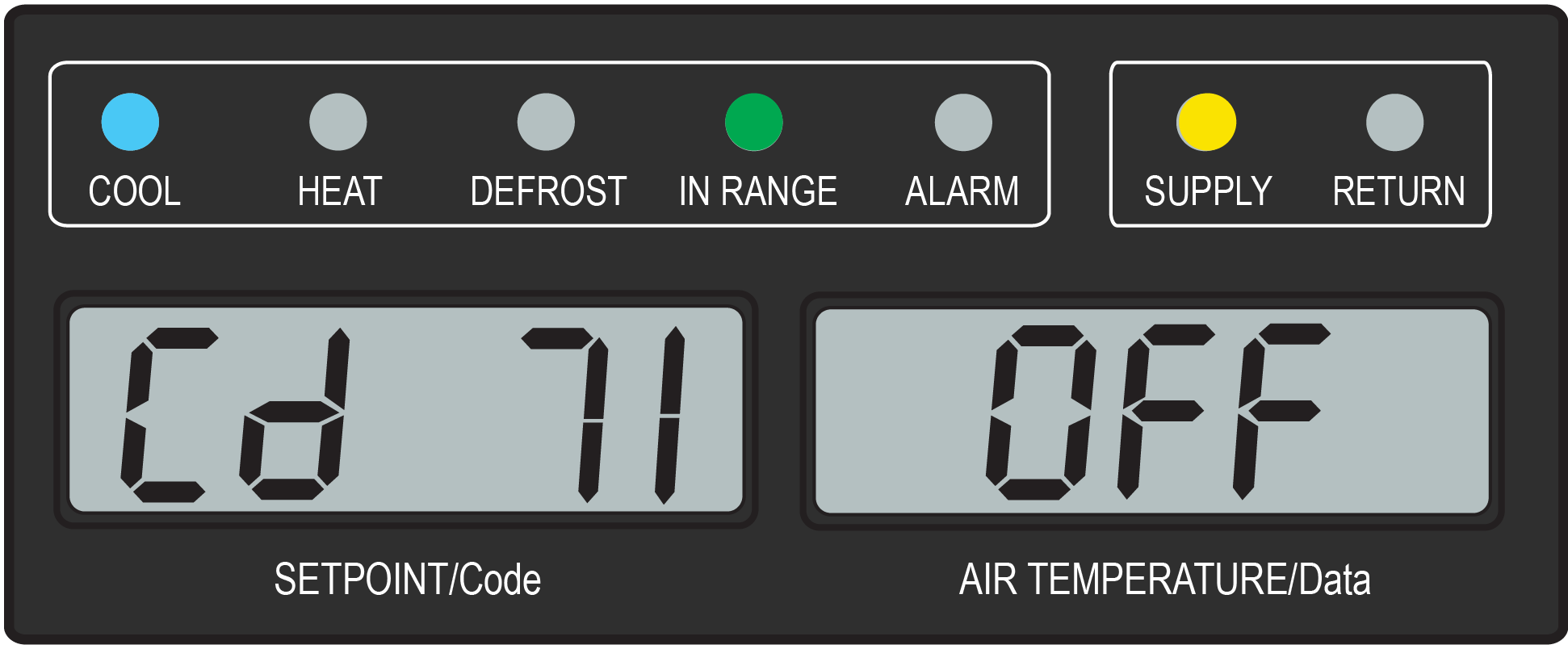
EverFRESH is activated via function code Cd71. This code allows the user to select a specific mode of operation and the associated parameters. The modes of operation are: “FrESh”, “OFF” and “PUrgE”. Fresh mode and Purge mode contain sub menus that have selectable parameters. When setting any mode of operation, the entire process must be followed to ensure all parameters are set.

When Fresh mode is active, the menu will toggle between the messages “FrESH ACtiV” and supply / return temperatures. If the optional Cd76 CO2 Injection is available and enabled, then the display will toggle between the selected CO2 mode (“FrESH” “A-CO2” or “FrESH” “PrCON”) and supply / return temperatures.
3.5.1Fresh Mode
In Fresh mode, all EverFRESH operations are enabled and setpoints for CO2 and O2 can be edited.
NOTE: The CO2 setpoint is the CO2 level allowed for the cargo. The range is 1 to 19% with a default setting of 5%.
NOTE: The O2 setpoint is the minimum level of oxygen allowed for the cargo. The range is 1 to 17% with a default setting of 10%.
1.Press the CODE SELECT key on the keypad.
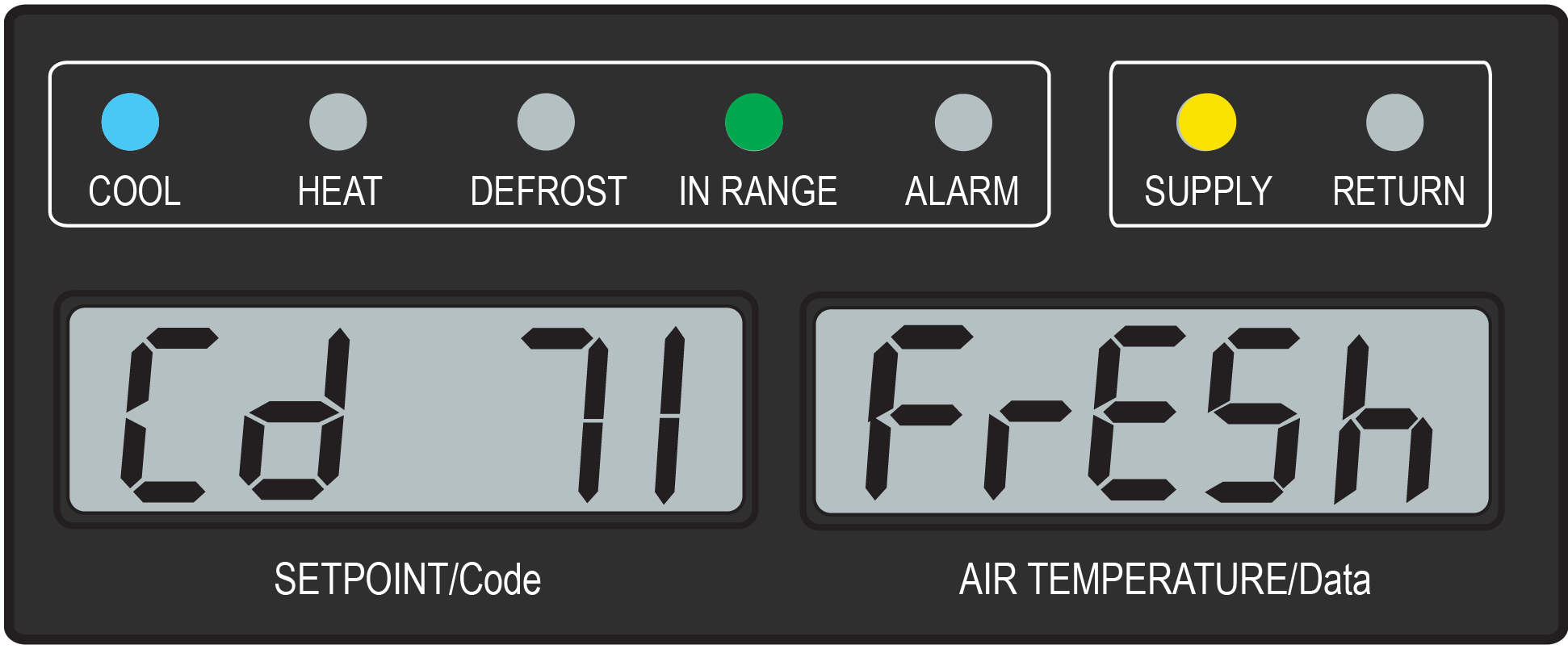
2.Use the Arrow keys until “Cd 71” is displayed, then press the ENTER key.
3.Use the Arrow keys until “FrESh” is in the right display, then press the ENTER key.
4.“CO2SP” appears in the left display with the setpoint value flashing in the right display. Press ENTER to keep the originally displayed value. Or, use the Arrow keys to change the CO2 setpoint and press ENTER to confirm.
Setpoint values in the 1.0 to 2.8 range are in 0.2 increments, while values in the 3.0 to 19.0 range are in 0.5 increments.
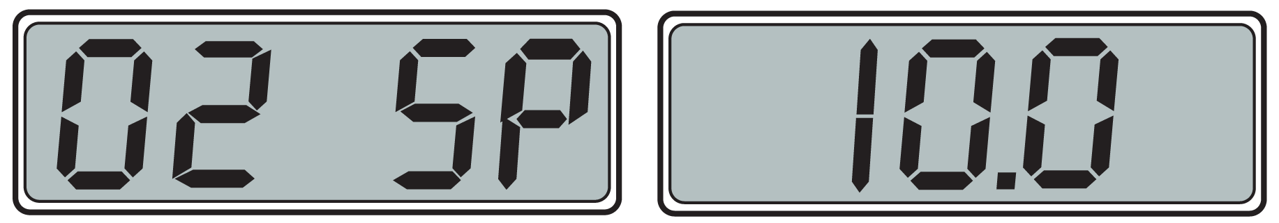
5.“O2 SP” appears in the left display with the setpoint value flashing in the right display. Press ENTER to keep the originally displayed value. Or, use the Arrow keys to change the O2 setpoint and press ENTER to confirm.
Setpoint values in the 1.0 to 2.8 range are in 0.2 increments, while values in the 3.0 to 17.0 range are in 0.5 increments.
When Off mode is selected, all EverFRESH operations will be disabled. The EverFRESH solenoids will be closed.
When a setpoint less than -1.0°C (30.2°F) is selected on the unit, Off mode is automatically enabled and the display will show dashes “-----”. The current EverFRESH setting will be saved.
1.Press the CODE SELECT key on the keypad.
2.Use the Arrow keys until “Cd 71” is displayed, then press the ENTER key.
3.Use the Arrow keys until “OFF” is displayed and press the ENTER key.
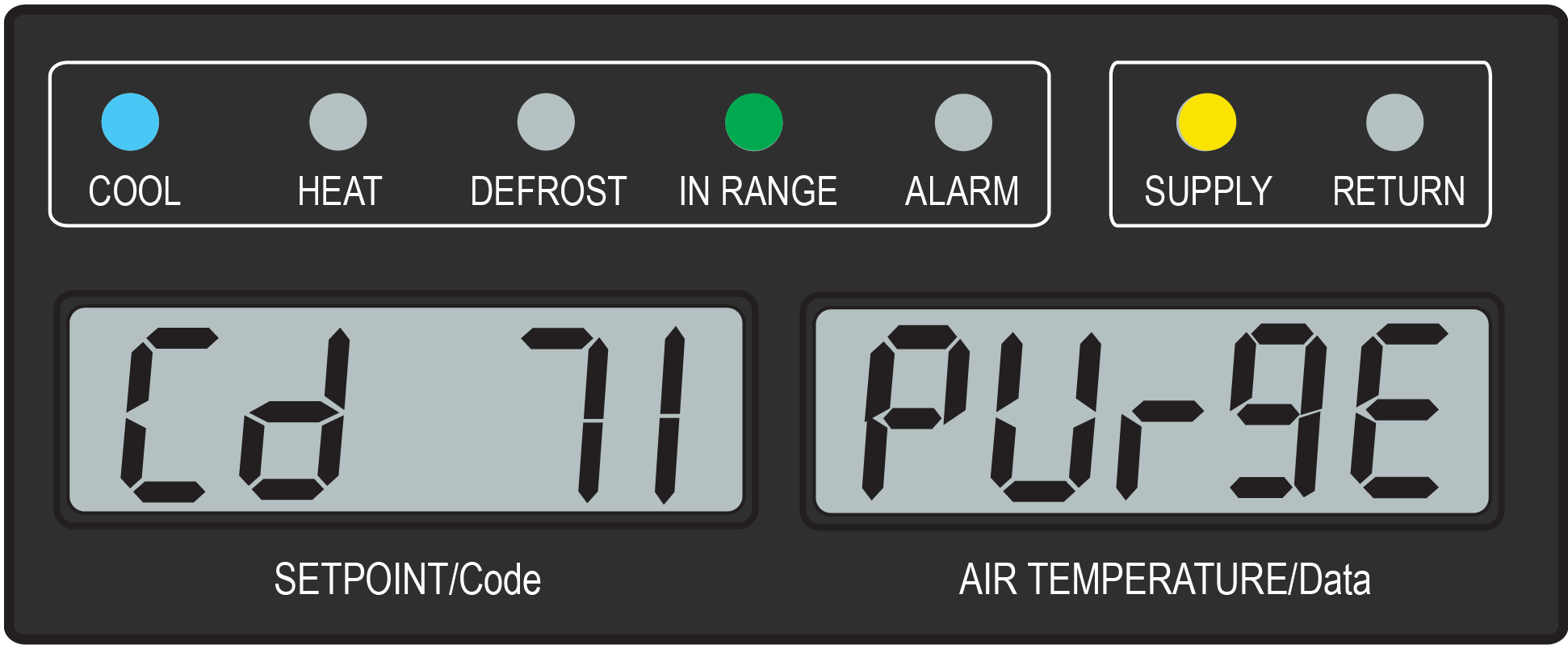
3.5.3Purge Mode
Purge mode is active, EverFRESH operations are suspended while gas levels are pre-charged in the container. All EverFRESH control actions and alarm 929 is suspended to purge the container to a desired gas concentration. When activated, Purge mode remains active for a period of time chosen from the Purge mode sub menu.
NOTE: The CO2 setpoint is the level of CO2 allowed for the cargo. The range is 1 to 19% with a default setting of 5%.
NOTE: The O2 setpoint is the minimum level of oxygen allowed for the cargo. The range is 1 to 17% with a default setting of 10%.
1.Press the CODE SELECT key on the keypad.
2.Use the Arrow keys until “Cd 71” is displayed, then press the ENTER key. The selection in the right display will blink.
3.Use the Arrow keys until “PUrgE” mode is displayed, then press the ENTER key.
4.“CO2SP” is in the left display with the setpoint value in the right display. Press ENTER to keep this value. Or, use the Arrow keys to change the CO2 setpoint and press ENTER to confirm.
Setpoint values in the 1.0 to 2.8 range are in 0.2 increments, while values in the 3.0 to 19.0 range are in 0.5 increments.
5.“O2 SP” in the left display with the setpoint value in the right display. Press ENTER to keep this value. Or, use the Arrow keys to change the O2 setpoint and press ENTER to confirm.
Setpoint values in the 1.0 to 2.8 range are in 0.2 increments, while values in the 3.0 to 17.0 range are in 0.5 increments.
6.With “PUrgE” in the left display, use the Arrow keys to toggle the right display to “On” or “OFF”, then press ENTER.
When “OFF” is selected, Purge mode is either not activated or terminated if it was previously activated.
When “On” is selected, “tim” is in the left display with the current purge time flashing in 1 to 10 hour increments selectable in 1 hour intervals (default 5 hours) in the right display. The “tim” value is the amount of time EverFRESH will be held off to allow charging and settling of gases.
7.Use the Arrow keys to change the time value and press the ENTER key to confirm and enter Purge mode.
8.Purge mode is now active. During Purge mode, while the timer is counting down the display toggles between the following:
•left display shows “PUrgE” and right display shows how much time remaining.
•left display shows temperature setpoint and right display shows the supply air temperature.
NOTE: If there is an alarm in the alarm list, the Purge mode countdown will not be displayed but Purge mode is still enabled.
9.When the Purge mode timer expires, Fresh mode is enabled and the unit reverts to normal temperature control display. Purge mode is terminated on power cycle, trip start, defrost or pre-trip.
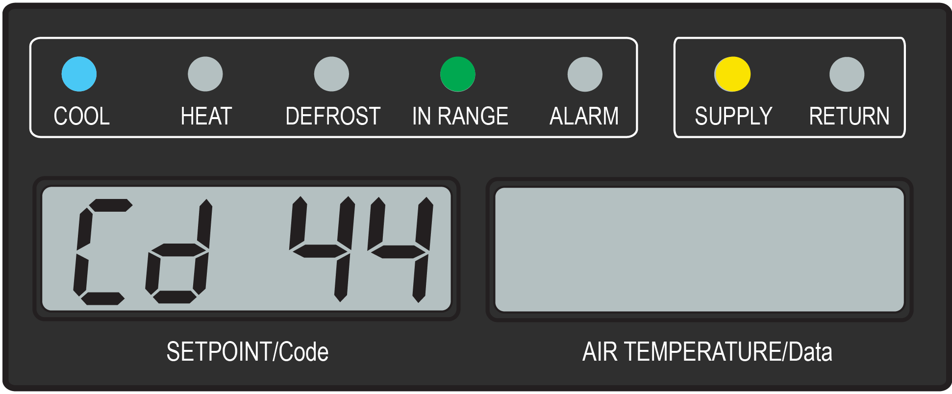
10.To view CO2 and O2 values during Purge mode, exit Cd71 by pressing the CODE SELECT key until “Cd 71” is in the left display. Then, use the Up Arrow key to bring up Cd44 and press ENTER.
3.5.4CO2 Injection Mode (Cd76)
CO2 Injection mode actively injects CO2 into the cargo space during transport. This mode is only available if the unit is configured with the CO2 injection option and Cd71 has been set to Fresh mode.
With the release of software 6326, there are two selectable modes of CO2 injection available: A-CO2 and PrCON (Pre-Conditioning).
1.Press the CODE SELECT key on the keypad.
2.Use the Arrow keys until “Cd 76” is in the left display, then press the ENTER key.
3.There are two selectable modes of operation available along with disabling CO2 injection (OFF). Use the Arrow keys and press ENTER to select the mode or turn off:
•“A-CO2”. In this mode, O2 pull down is completed by the assistance of CO2 injection until the CO2 levels reach setpoint, then setpoint is maintained. This mode remains active for the trip.
•“PrCON”. This mode follows A-CO2 logic to assist CO2 injection. When CO2 levels reach setpoint during O2 pull down, this mode is complete and CO2 injection is turned OFF. The EverFRESH operating mode will then revert to normal operation (Fresh mode).
•“OFF”. CO2 injection is disabled.
4.When A-CO2 Mode is active, the display will toggle between the message “FrESH” | “A-CO2” and the setpoint (left) with supply or return temperature (right).
When PrCON Mode is active, the display will toggle between the message “FrESH” | “PrCON” and the setpoint (left) with supply or return temperature (right).
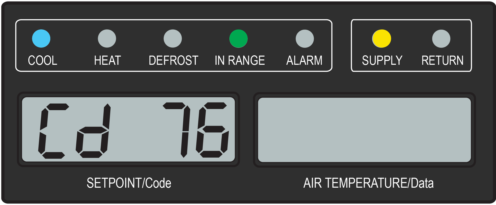
3.6Viewing EverFRESH System Values
3.6.1Code 44 (Cd44)
Cd44 is for viewing the following EverFRESH values: CO2 setpoint, CO2 percentage, O2 setpoint, O2 percentage, O2 voltage and Membrane Pressure Transducer (MPT) pressure.
1.Press the CODE SELECT key on the keypad. Use the Arrow keys until “Cd 44” is in the left display, then press the ENTER key.
2.Press the Down Arrow key to begin viewing the values available in this sub menu. Once navigation begins, use either Up or Down Arrow key to navigate.
NOTE: Once scrolling through all values brings up Cd44 again in the left display, ENTER will need to be pressed to re-enter the sub menu.
|
|
|
|
|
|
|
|
|
|
|
|
|
|
|
|
Membrane Pressure Transducer (Bar / PSIG) |
|


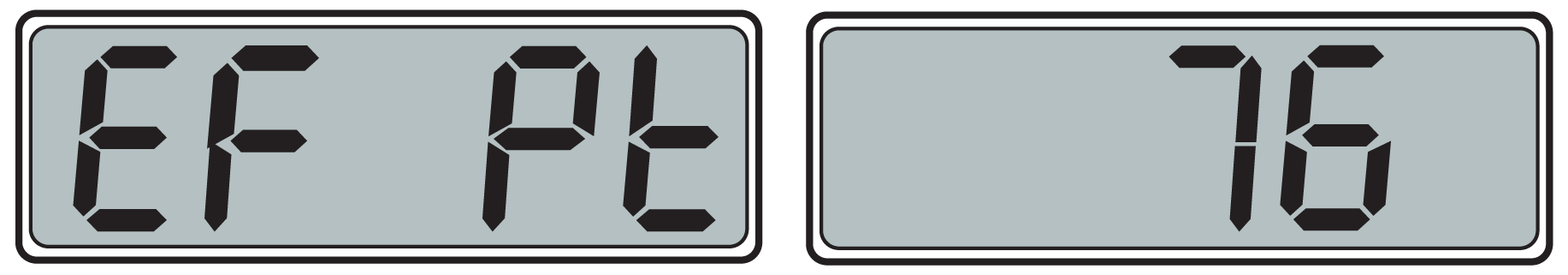
Cd72 displays the total hours of air compressor run time since last service. When the timer exceeds 5000 hours since last reset, the display will cycle the message “CA” “ChECk” until the timer is reset again. If a unit does not have the EverFRESH option, Cd72 displays dashes “-----”.
1.Press the CODE SELECT key on the keypad. Use the Arrow keys until “Cd 72” “ACHrS” is on the display, then press the ENTER key.
2.Use the Arrow keys to toggle between the following selections:
•“####” - Number of hours of air compressor run time since service.
•“rESEt” - Prompt to reset the hours. Press the ENTER key for five seconds to reset the counter to 0.
Cd73 displays the total hours of operational hours for the EverFRESH system and air compressor. The total hours are displayed in increments in 10 hours (i.e. 3000 hours will be displayed as 300). If a unit does not have the EverFRESH option, Cd73 displays dashes “-----”.
1.Press the CODE SELECT key on the keypad. Use the Arrow keys until “Cd 73” “ACHrS” is on the display, then press the ENTER key.
2.Use the Arrow keys to toggle between the following selections:
•“####” - Number of hours of total air compressor run time.
•“rESEt” - Prompt to reset the hours. Press the ENTER key for five seconds to reset the counter to 0.
Cd78 displays the state of the EverFRESH air compressor as On or OFF. This code has no sub menu.
Cd79 displays the state of the EverFRESH water drain valve (WDV) as On or OFF. This code has no sub menu.
Cd80 displays the state of the EverFRESH air valve (EAV) as On or OFF. This code has no sub menu.
Cd81 displays the state of the EverFRESH CO2 valve as On or OFF. This code has no sub menu.
3.7Container Venting Procedure
Potential hazardous atmosphere and low oxygen levels may exist inside the container. Ventilate before entering. Stay away from doors and access panels while venting.
1.Set the Start-Stop (ST) switch to the “I” position to turn the unit On.
2.Fully open the manual fresh air vent.
NOTE: Avoid any direct breathing of the venting gases from the manual fresh air vent.
3.Go to Cd71, select Fresh mode and set the operating parameters to 17% O2. See Section 3.5.1 for Fresh mode procedure.
4.Allow the refrigeration unit to run. This allows the evaporator fans to exchange low-oxygen level air with ambient air.
5.Monitor the container internal environment via Cd44. See Section 3.6.1 for Cd44 description.
6.When the oxygen level reaches a safe level of approximately 20%, open both of the container rear doors and pull back the curtain to facilitate the clearing of the hazardous atmosphere. Step away from the container rear doors. Continue refrigeration operation for five minutes prior to entry or unloading of the container.