Section 6
Before servicing unit, make sure the Start-Stop switch (ST) is in the OFF position. Unit circuit breaker (CB-1) and external power sources are turned OFF and tagged to prevent accidental energizing of circuits.
Potential hazardous atmosphere and low oxygen levels inside the container, ventilate before entering. Stay away from doors while venting (refer to Section 4.7).
Prior to performing service work, a thorough review and understanding of the entire manual is recommended.
6.2.1Removing the Panel Air Filter(s)
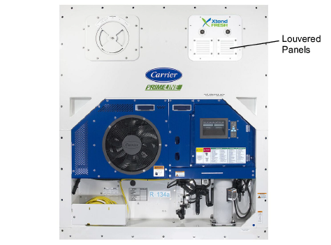
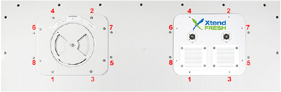
1.Remove the louvered panels from the right-hand side refrigeration evaporator access panel (Figure 6.1) by removing the bolts, flat washers, and rubber washers.
2.Loosen two #10-32 nuts that secure the brackets holding the air filter in place.
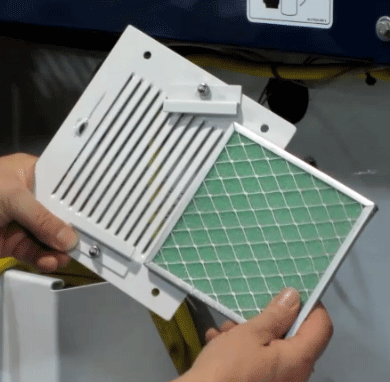
3.Slide the panel air filter(s) out (Figure 6.2).
Figure 6.2 Panel Air Filter(s)
6.2.2Replacing the Panel Air Filter(s)
1.Install the panel air filter by reversing the above steps. Be sure the filter is fully inserted until it hits the stop. Also be sure to install the filters in the correct air flow direction. The filter’s wire mesh must be facing towards the inside of the container.
Potential hazardous atmosphere and low oxygen levels inside the container, ventilate before entering. Stay away from doors while venting. Refer to Section 4.7.
Before servicing unit, make sure the Start-Stop switch (ST) is in the OFF position. Unit circuit breaker (CB-1) and external power sources are turned OFF and tagged to prevent accidental energizing of circuits.
6.3.1Removing the Sensor Air Filter Element
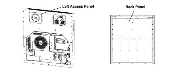
When replacing the Sensor Air Filter element it can be accessed in two ways: through the left-hand side evaporator access panel or through the inside of the container by removing the upper back panel (Figure 6.4). Refer to Section 6.6 for procedures to remove and install the left access panel.
Figure 6.4 Left Access Panel and Back Panel (Inside of Container)
1.Follow container venting procedures before performing any maintenance on the sensor air filter element. Refer to Section 4.7.
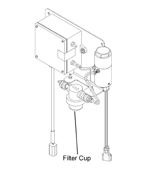
2.By hand, unscrew and remove the filter cup from the bottom of the sensor air filter assembly (Figure 6.5).
3.Remove the filter element from the filter assembly.
6.3.2Replacing the Sensor Air Filter Element
1.Install the sensor air filter element by reversing the above steps.
6.4.1Removing the Oxygen Sensor
When replacing the oxygen sensor it can be accessed in two ways: through the left-hand side evaporator access panel or through the inside of the container by lowering the upper evaporator panel (Figure 6.4). Refer to Section 6.6 for procedures to remove and install the left access panel.
Potential hazardous atmosphere and low oxygen levels inside the container, ventilate before entering. Stay away from doors while venting. Refer to Section 4.7.
Before servicing unit, make sure the Start-Stop switch (ST) is in the OFF position. Unit circuit breaker (CB-1) and external power sources are turned OFF and tagged to prevent accidental energizing of circuits.
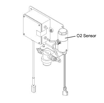
1.Follow container venting procedures before performing any maintenance on the oxygen sensor (Figure 6.6).
2.Remove the cushion clamp, if equipped, and screws that secure the oxygen sensor.
3.Cut the wire tie that secures the wiring to the oxygen sensor body.
4.Unplug the wiring connector from the receptacle.
5.Remove the oxygen sensor from the oxygen sensor housing.
6.4.2Replacing the Oxygen Sensor
1.Install the oxygen sensor by reversing the above steps.
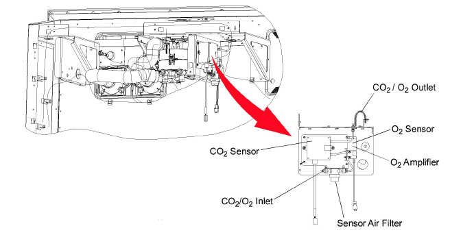
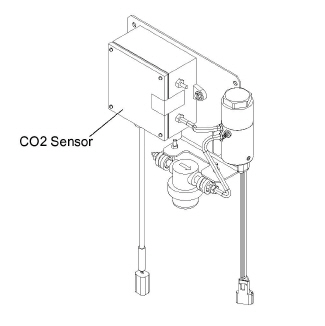
When replacing the CO2 sensor it can be accessed in two ways: through the left-hand side evaporator access panel or through the inside of the container by removing the upper back panel (Figure 6.4). Refer to Figure 6.3 for the physical location of the CO2 sensor. Refer to Section 6.6 for procedures to remove and install the left access panel.
Potential hazardous atmosphere and low oxygen levels inside the container, ventilate before entering. Stay away from doors while venting. Refer to Section 4.7.
Before servicing unit, make sure the start-stop switch (ST) is in the OFF position. Unit circuit breaker (CB-1) and external power sources are turned OFF and tagged to prevent accidental energizing of circuits.
1.Follow container venting procedures before performing any maintenance on the CO2 sensor.
2.Remove the electrical connector and the inlet and outlet tubes from the body of the sensor (Figure 6.3).
3.Loosen the screws which holds the CO2 sensor to the fan deck bracket.
4.Install replacement CO2 sensor by reversing steps 2 and 3.
5.Calibrate the CO2 sensor, following the test procedure. Refer to Section 4.5.3.
Before servicing unit, make sure the Start-Stop switch (ST) is in the OFF position. Unit circuit breaker (CB-1) and external power sources are turned OFF and tagged to prevent accidental energizing of circuits.
6.6.1Removing the XtendFRESH Access Panel
1.Remove the two louvered panels from the upper right access panel (Figure 6.1) by removing the mounting bolts and T.I.R locking device if used.
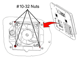
2.Remove the eight #10-32 nuts holding the ducts in place. Leave the blower fan mounted to its duct. Gently push the duct away from the back of the panel (Figure 6.8).
Figure 6.8 Blower Fan Nut Locations
3.Remove the access panel mounting bolts and T.I.R. locking device if used.
4.Carefully pull the access panel out slightly to reach inside of the unit and unplug the fresh air solenoid and fan connectors.
5.Set the panel aside to make any necessary repairs.
6.6.2Re-installing the XtendFRESH Access Panel
1.Plug in the fresh air solenoid and fan connections, on the back of the access panel.
2.Install the access panel and secure with mounting hardware.
3.Reach into the access panel and pull the transition ducts into position of the access panel. Make sure the gasket is properly seated.
4.Secure the ducts in place with eight #10-32 nuts (Figure 6.8).
5.Re-attach the louver panels. Torque the panel bolts to 60 in/lbs. (6.8 Nm), using the torque sequence shown in Figure 6.9. Repeat the torque sequence twice for a proper seal.
6.6.3Replacing the XtendFRESH Fan(s)
1.Remove the two louvered panels from the upper right access panel (Figure 6.1) by removing the mounting bolts and T.I.R. locking device if used.
2.Unbolt the defective fan from the panel. Unplug the blower connections. Make note of the fan direction.
3.Replace the defective fan, making sure the fan will be turning in the proper direction. The fan on the right side should have the label showing, and the left fan the label should be on the inside facing the transition.
4.Re-attach the fan wiring connections.
5.Inspect the air filter(s). Clean or replace as needed.
6.Install the louvered panel with filters to the access panel.
6.7.1Removing the Scrubber Filter
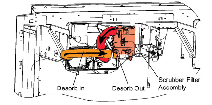
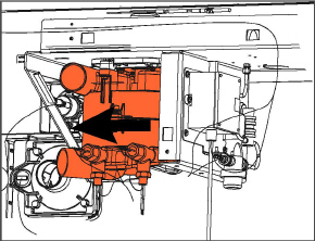
When replacing the Scrubber it can be accessed through the inside of the container. Refer to Figure 6.10 for the physical location of the Scrubber.
Figure 6.10 Hose/Scrubber Locations
1.Lower the back panel (Figure 6.4).
2.Unplug the scrubber heaters.
3.Loosen the hose clamps and remove the hose from the scrubber filter assembly, top and bottom (Figure 6.10).
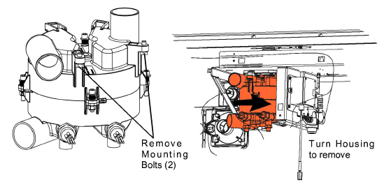
4.Remove the two bolts securing the scrubber housing to the top mounting bracket. Turn the scrubber housing 10 degrees to remove it from the unit (Figure 6.11).
Original XtendFRESH units have a tall exhaust port and port cap (Figure 3.2) and need to be removed in order to remove the housing.
Figure 6.11 Removing the Scrubber Housing
5.Move the scrubber housing to a clean area for disassembly.
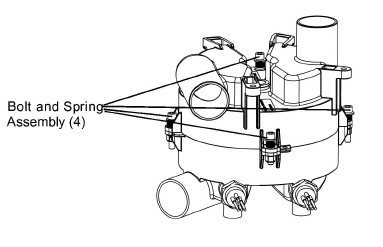
6.Remove the four bolt and spring assemblies holding the scrubber housing together (Figure 6.12).
Figure 6.12 Scrubber Bolt/Spring Assemblies
7.Separate the upper and lower halves of the scrubber housing.
8.Remove the carbon filter from the scrubber housing along with the gaskets and aluminum seal plate (Figure 6.13).
Figure 6.13 Scrubber Separated with Filter
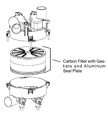
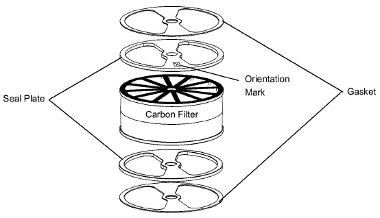
9.Install the seal plates and gaskets. Replace if damaged. Reinstall the new filter, making sure the gasket and seal plate are in the proper position. The side of the seal plate with the X must be installed towards the gasket (Figure 6.14).
Figure 6.14 Carbon Filter with Gasket and Seal Plate
10.Place the top plate and gasket on the top of the filter. Align the top housing so that the gasket and aluminum plate fit into the recess in the housing.
11.Bolt the housing together with the bolt and spring assemblies (Figure 6.12).
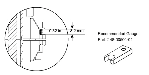
12.When tightening the spring assemblies the spring gap must be 0.310 inches (8mm) between the bottom of the washer and the housing tab surface (Figure 6.15).
Figure 6.15 Bolt / Spring Assembly Dimension
1.Align the scrubber shaft in the slot of the coupling attached to the motor.
It will aid in the installation if the shaft coupling (on top of the shaft) is loose to help with self-alignment. It will tighten during motor rotation.
2.The scrubber requires a ten degree turn in order to secure the back portion into the mounting tabs (Figure 6.16).
3.Connect the hoses from the air ducts to the scrubber housing (Figure 6.10).
4.Make sure the hose is completely on the housing, tighten the hose clamps and use cable ties to secure the hoses to the gusset. Be sure the hoses are level.
5.Reconnect the scrubber heaters. Use cable ties to secure the wiring to prevent chafing.
6.7.3Replacing the Scrubber Motor
When replacing the Scrubber motor it can be accessed through the inside of the container. Refer to Figure 6.10 for the physical location of the motor.
1.Start by removing the scrubber housing. Refer to Section 6.7.1
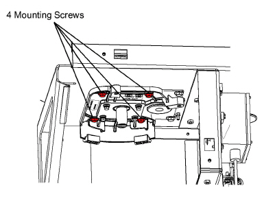
2.After removing the scrubber housing remove the four 1/4-20 mounting screws that attach the scrubber mounting plate to the fan deck (Figure 6.17).
Figure 6.17 Scrubber Mounting Plate
3.Carefully lower the plate while unplugging the scrubber motor connection. It may be necessary to cut the wire ties.
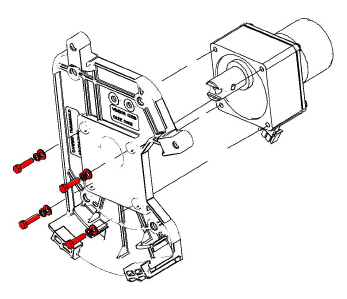
4.Remove the four hex head screws holding the motor to the mounting plate (Figure 6.18).
Figure 6.18 Motor and Mounting Plate
5.Replace the motor and follow the instructions in reverse order.
6.8.1Replacing the Fresh Air Solenoid
1.Remove the right-hand evaporator panel. Refer to Section 6.6.1.
2.There are two solenoids in the panel. The one on the left, as facing the panel from the back, requires the removal of a cover plate to access the four mounting screws. Remove the four 10-24 mounting screws.
3.Remove the 10-24 nuts and replace the defective solenoid by reversing steps 1-3.
For units equipped with XtendFRESH and a Vent Position Sensor, there is a solid state switch that will change depending on unit operation. If the unit is in XtendFRESH mode (Cd43 set to “FrESH”), the signal provided to the controller will be sent from the Oxygen sensor. If Cd43 is set to “OFF”, the signal to the controller will be sent from the Vent Position Sensor (VPS).
To check the operation of the VPS switch, bring up Cd43 set the option to “OFF”. Navigate to Cd45 and then open the manual fresh air panel and verify the sensor is reading in Cd45. Go back to Cd43 and activate XtendFRESH (“FrESH”). Cd44 should now show the CO2 and O2 values. Cd45 should display “----“.
Depending on equipment owner configuration, XtendFRESH may be turned “ON” or “OFF” after an AUTO PTI or TripStart. An individual Pre-Trip test or Cd43 “tESt” mode will not change the current state of XtendFRESH.
To ensure a successful XtendFRESH trip the following pre-trip steps should be performed prior to each trip. The following procedure is to be used in alignment with the 5369 release or higher.
1.Remove the rear upper back panel.
2.Press the CODE SELECT key on the keypad.
3.Press the Arrow keys until Code Select Cd18 is displayed then press the ENTER key. Verify that the container has software version (5369 or higher).
4.Then go to Code Select Cd43 and select “tESt” mode. Refer to Section 4.5.3 for procedure.
5.This initiates a mechanical component operational test which is a visual inspection, followed by a CO2 calibration and O2 sensor check.
Refer to Cd43 Test Mode described under Section 4.5.3 for description of mechanical and sensor tests.
Do not run the Calibration tests under loaded conditions.
6.On completion of the Cd43 test, prepare the box for an air leak test.
7.Check the defrost drain hose for any damage and ensure that the trap is filled with water.
8.Reinstall the upper back panel and ensure the floor drains within the container are sealed.
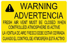
9.Ensure the manual fresh air panel is closed tight and that the warning label is in place on the unit.
10.Check air tightness of the box following the Box Checkout/Leak Test procedure. Refer to Section 6.11.1. The box must meet or exceed the air tightness requirement.
11.Load cargo, install the new curtain and select the desired O2 and CO2 levels via Code Select Cd43 “FrESh” modes. Refer to Section 4.5.1.
12.Immediately after the cargo is loaded it is recommended to perform a second leak test on the box.
Check the rear container doors and door handles for proper operating condition. Check for proper installation of labels on the container and refrigeration unit. Always visually check the inside of the container for occupants prior to closing the doors.
When using the XtendFRESH system, the box must conform to leak rates in order to maintain control of the O2 and CO2 setpoints. The minimal box requirement is a pressure decay of 2 inch WG (50mm) to 1 inch WG (25mm) of eight minutes or more for a 40 foot container and four minutes or more for a 20 foot container. It is recommended that it be checked prior to the voyage.
To perform this check some units may be equipped with two pressure connection ports on the front of the unit. If the ports are not available then a Manual Fresh Air panel (part number 79-04098-00) with two Schrader ports should be installed.
Figure 6.20 Container Leakage Test Ports
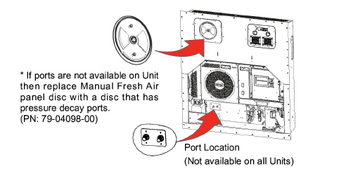
One of the ports is connected to a pressurized air supply and the other is connected to a Magnehelic pressure gauge. The pressure gauge monitors the container leakage rate.
Prior to performing the leak test:
•Seal the floor drains with plugs
•Ensure the unit condensate drain line is filled with water
•Ensure the air makeup panel is tightly closed
•Insert plug in drain hose. Install container curtain at the rear door
•Seal the door shut
When installing the door curtain (part number 76-50036-01), place the curtain around the door and seal the curtain along the top and sides of the box and close the door. The curtain should be visible throughout the perimeter of the doors. Tape may be used to assist in holding the curtain in position. Always use a new curtain as a small rip in the curtain can result in a failure of the test.
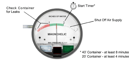
After connecting the gauges, turn on the air supply and regulate the air pressure to 40-60 psi. When the Magnehelic gauge reads 2.5 inches of water gauge, shut off the air supply. Do not exceed 3.0 inches of WG.
Monitor the Magnehelic pressure gauge for the drop in air pressure in the container. When the Magnehelic pressure gauge reads 2 inches, start a timer. When the Magnehelic pressure gauge reads 1 inch of WG, stop timing. The amount of time expired should be no less than eight minutes or more for a 40 foot container and four minutes or more for a 20 foot container. If it is less than the required time (i.e six minutes), then the container needs to be checked for leaks.
Figure 6.21 Magnehelic Gauge (Kit # 07-00177-20)
External Checks:
Check for leaks with the following recommended checks. Re-pressurize the container to 2 inches water gauge and look for leaks at the following areas using soapy water (mixture of dish detergent and water) looking for bubbles.
•Inspect evaporator unit access panels. Check gasket is properly in place. Tighten access panel bolts to 60 inch-lbs. and caulk if necessary.
•Inspect at condensate drain outlet line. If leaking, complete other checks and re-inspect internally.
•Inspect unit/container box joints. Caulk if necessary.
•Inspect the through-wire bulkhead connections. Secure and caulk if required.
•Inspect the container floor drains under container (if accessible). If leaking, complete external checks and reinspect internally.
•Inspect the rear door seals. Ensure curtain is properly installed (curtain should be visible throughout the perimeter of the doors). Remove an install new curtain. De-pressurize the container prior to opening the container.
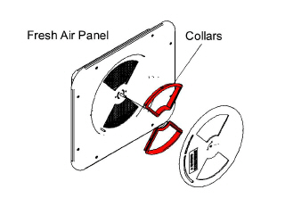
•Ensure manual fresh air panel is equipped with collars (Part # 79-04064-00).
Figure 6.22 Fresh Air Panel Collars
Internal Checks:
Remove pressure within the container and perform inspections at the following locations.
•Inspect curtain for any rips. Replace curtain
•Inspect the container floor drains. Ensure they are properly sealed. Standard drains can not be used.
•Inspect condensate drain outlet line. Confirm drain line is filled with water.
•Inspect for any internal wall damage. Repair and caulk as required
•Inspect floor to side wall joint, floor to front bulkhead joint for any damage. Repair and caulk as required
On completion of the checks and any associated repairs it is recommended that the unit be tested again to verify it that it now meets the required level.
6.11.2Initialize XtendFRESH Atmospheric Conditions
The purpose of this procedure is to create optimal conditions that have been studied and shown to slow the ripening cycle of some commodities by the use of nitrogen (N2) and carbon dioxide (CO2) gas cylinders.
Procedure:
1.Open the manual fresh air vent to allow for charging of gas.
If unit is equipped with a Vent Position Sensor (VPS):
a.Bring up Cd43 on the display and set to Off mode to disable all XtendFRESH operations.
b.Bring up Cd45.
c.Open the manual fresh air vent until the display reads 10 CFM.
If unit is not equipped with a Vent Position Sensor (VPS):
a.Open the manual fresh air vent until the indicator points to approximately 9 CFM.
Do not inject gas into the container unless the manual fresh air vent is opened. Damage to the unit and risk of personal injury exists if a pressure relief pathway is not established.
2.Enable Purge mode using Cd43. This is done to establish the amount of time to purge the unit of O2 and CO2. Refer to Section 4.5 for procedure.
If not using Purge mode, the CO2 and O2 levels can be viewed in Cd44.
3.Purge mode is now active.
4.To establish the proper level of O2 in the unit, charge with N2 gas. Connect the hose from the N2 regulator to the unit equipped gas injection port. Then, start releasing N2 gas until the O2 levels reach the desired level.
If injection pressure is too high, then there is a risk of clearing the unit defrost condensate trap. If this happens, the condensate trap will need to be refilled with water. If condensate trap has been cleared of water, then a leak exists that will hinder atmosphere control.
5.To establish the proper level of CO2 in the unit, charge with CO2 gas. Connect the purging hose to the CO2 regulator. After injection, the sensor may read much lower than this for at least a half hour.
Increasing the CO2 pressure too high will run the risk of freezing the regulator. Due to mixing and sensor lag, the CO2 level will continue to rise for some time after stopping the CO2 regulator.
6.Once the Purge mode timer is expired, remove the gas injection hose connections and close the manual fresh air vent. If gas concentrations reach desired levels prior to the timer expiring, set Purge mode in Cd43 to OFF prior to closing the manual fresh air vent. When the timer is expired or Purge mode is set to OFF to disable it, the unit will revert to Fresh mode using the setpoints entered for Purge mode.
Potential hazardous atmosphere and low oxygen levels inside the container, ventilate before entering. Stay away from doors while venting. Refer to Section 4.7.
1.Open the rear doors of the container.
2.Use a new curtain.
3.Fully unfold the door curtain package and hold it up to the container opening. Tape maybe be used to assist holding the curtain in position.
4.Place curtain around door and seal curtain along top and sides of box. Install in track if available.
5.Close the rear doors of the container.