Service
EXPLOSION HAZARD Failure to follow this WARNING can result in death, serious personal injury and / or property damage. Never use air or gas mixtures containing oxygen (O2) for leak testing or operating the product. Charge only with refrigerants R-134a or R-513A as specified for the unit model number: Refrigerant must conform to AHRI Standard 700 specification.
The scroll compressor achieves low suction pressure very quickly. Do not use the compressor to evacuate the system below 0 psig. Never operate the compressor with the suction or discharge service valves closed (frontseated). Internal damage will result from operating the compressor in a deep vacuum.
To prevent trapping liquid refrigerant in the manifold gauge set, make sure set is brought to suction pressure before disconnecting.
When charging the unit with R-513A refrigerant, charge as a liquid only. R-513A is an azeotrope blend containing R-1234yf and R-134a. Charging or topping off as a vapor will result in an incorrect mixture of blend in the system.
NOTE: Use a refrigerant recovery system whenever removing refrigerant. When working with refrigerants you must comply with all local government environmental laws. In the U.S.A., refer to EPA section 608.
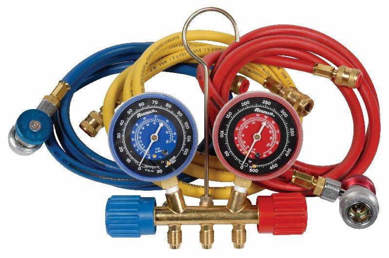
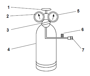
The manifold gauge set, as shown in Figure 7.1, contains self-sealing hoses and couplers. The manifold gauge set connects to a refrigeration system to determine system operating pressures, add refrigerant charge and to equalize or evacuate the system. The set is available from Carrier Transicold, part number 07-00294-00 or 07-00294-05 (metric). Hoses are refrigeration and/or evacuation hoses (SAE J2196/R-134a).
NOTE: It is recommended to dedicate the manifold gauge set to a specific refrigerant (R-134a or R-513A).
Figure 7.1 Manifold Gauge Set
The gauge set layout with hoses and couplings is shown in Figure 7.2. The gauge set connects to the service connections on the refrigeration unit using the blue and red hoses. Service connections are described in Section 7.1.3. The yellow hose is a utility connection that can be connected to a a refrigerant cylinder or vacuum pump.
Once connected, the following procedures can be performed:
•Checking system operating pressures. When the hand valves on the gauge set are frontseated (turned clockwise), the gauges will read system pressure.
•Removing refrigerant charge
•Evacuating and dehydrating the system
•Adding refrigerant charge
Turning the hand valves clockwise will frontseat the valve (closed) to read system pressures at the gauge.
Turning the hand valves counter-clockwise will backseat the valve (open) to allow flow to the rest of the gauge set and hoses.
Figure 7.2 Manifold Gauge Set Layout
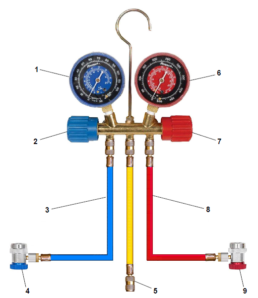
1)Suction Pressure Gauge (low side)
2)Suction Hand Valve (low side)
3)Suction Hose (low side)
4)Suction Coupling (low side)
5)Utility connection
6)Discharge Pressure Gauge (high side)
7)Discharge Hand Valve (high side)
8)Discharge Hose (high side)
9)Discharge Coupling (high side)
- - - - -
7.1.2Evacuating the Manifold Gauge Set
If a manifold gauge set is new or was exposed to the atmosphere, it will need to be evacuated to remove contaminants and air. This is done while the gauge set blue and red hoses are not connected to the service connections. Follow the procedure below.
1.Backseat (turn counterclockwise) both service couplings
2.Midseat both hand valves.
3.Connect the yellow hose to a vacuum pump and refrigerant cylinder.
4.Evacuate to 10 inches of vacuum
5.Charge with refrigerant to a slightly positive pressure of 0.1 kg / cm2 (1.0 psig).
6.Frontseat (turn clockwise) both hand valves.
7.Disconnect from the cylinder. The gauge set is now ready for use.
7.1.3Service Connections
There are three service valves on the unit for connecting to the manifold gauge set and performing refrigerant service: compressor suction section valve and compressor discharge service valve and the liquid line (king) service valve. The service valves are provided with a double seat and an access valve which enables servicing of the compressor and refrigerant lines. See Figure 7.3 for diagram.
See Figure 3.18 for compressor suction valve and discharge valve.
See Figure 3.19 for liquid line valve.
Figure 7.3 Service Valve
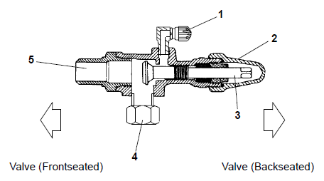
1)Access Valve
2)Service Valve Stem Cap
3)Service Valve Stem
4)Compressor or Filter Drier Inlet Connection
5)Line Connection
- - - - -
Turning the service valve stem clockwise will frontseat the valve to close off the line connection and open a path to the access valve.
Turning the service valve stem counterclockwise will backseat the valve to open the line connection and close off the path to the access valve.
With the service valve stem midway between frontseat and backseat, both of the service valve connections are open to the access valve path. For example, the valve stem is first fully backseated when connecting a manifold gauge to measure pressure. Then, the valve is opened 1/4 to 1/2 turn to measure the pressure.
7.1.4Connecting the Manifold Gauge Set
Connection of the manifold gauge set is dependent on the procedure performed or components serviced.
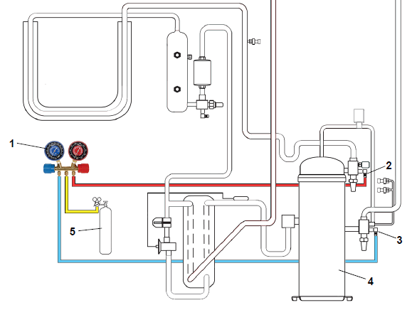
For reading system pressures, performing a manual pump down, or checking refrigerant charge, the manifold gauge set connects to the suction service valve (blue hose) and discharge service valve (red hose):
See Figure 7.4 for illustration.
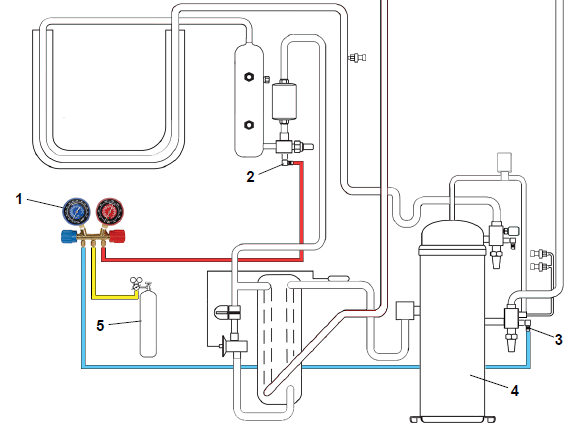
For the procedure for adding a partial refrigerant charge, the manifold gauge set connects to the suction service valve (blue hose), discharge service valve (red hose) and refrigerant cylinder (yellow hose).
See Figure 7.5 for illustration.
For the procedure for adding a full refrigerant charge, the manifold gauge set connects to the suction service valve (blue hose), liquid line service valve (red hose) and refrigerant cylinder (yellow hose).
See Figure 7.6 for illustration.
For the procedure to evacuate and dehydrate the system, see Section, the manifold gauge set connects to the refrigerant recovery system (blue hose), vacuum micron gauge (red hose) and vacuum pump (yellow hose). The service valves (suction, discharge, liquid line) all connect with evacuation hoses directly to the vacuum pump.
See Figure 7.7 for illustration.
Figure 7.4 Connection for Reading Pressures, Manual Pump Down and Checking Charge
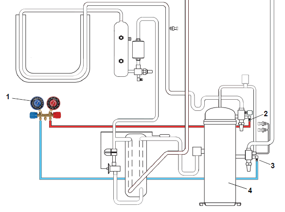
1)Manifold Gauge Set
2)Discharge Service Valve
3)Suction Service Valve
4)Compressor
- - - - -
Figure 7.5 Connection for Adding a Partial Charge
1)Manifold Gauge Set
2)Discharge Service Valve
3)Suction Service Valve
4)Compressor
5)Refrigerant Cylinder
- - - - -
Figure 7.6 Connection for Adding a Full Charge (Liquid)
1)Manifold Gauge Set
2)Liquid Line Service Valve
3)Suction Service Valve
4)Compressor
5)Refrigerant Cylinder
- - - - -
Figure 7.7 Connection for Evacuation and Dehydration
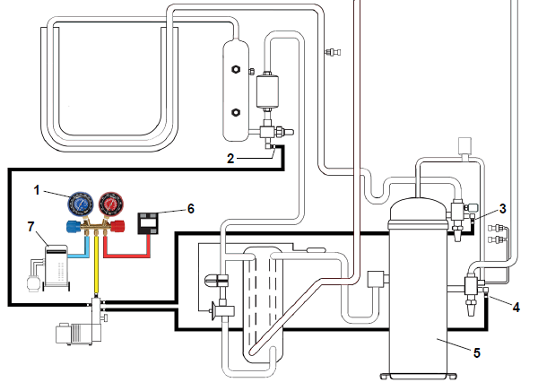
1)Manifold Gauge Set
2)Liquid Line Service Valve
3)Discharge Service Valve
4)Suction Service Valve
5)Compressor
6)Vacuum Micron Gauge
7)Refrigerant Recovery System
8)Vacuum Pump
- - - - -
7.1.4.1 Connect the Manifold Gauge Set to Access Valves
1.Verify that both hand valves on the manifold gauge set are fully closed.
2.Remove the service valve stem cap and make sure the service valve is backseated.
3.Remove the service access valve cap.
4.Connect the hose coupling to the service access valve; blue for suction (low side), red for discharge (high side).
5.Repeat the steps to connect the gauges to both suction (low side) and discharge (high side).
7.1.4.2 Removing the Manifold Gauge Set from Access Valves
1.While the compressor is still ON, backseat the discharge (high side) service valve.
2.Midseat both gauge set hand valves and allow the pressure in the gauge set to be drawn down to suction (low side) pressure. This returns any liquid that may be in the discharge (high side) hose to the system.
To prevent trapping liquid refrigerant in the manifold gauge set, make sure set is brought to suction pressure before disconnecting.
3.Backseat the suction (low side) service valve.
4.Backseat both service couplings.
5.Frontseat both hand valves on the manifold gauge set.
6.Remove both couplings from the access valves.
7.Install both service valve stem caps and service port caps, finger-tight only.
1.Connect the manifold gauge set to the suction service valve and discharge service valve.
See Section 7.1.4.1 for procedure to connect to valves. See Figure 7.4 for connection diagram.
2.Make sure both hand valves on the manifold gauge set are fully closed.
3.For suction pressure, turn the blue coupling (low side) knob clockwise to open the system to the manifold gauge set.
4.Slightly midseat the suction service valve to read system low side pressure at the manifold gauge set.
5.For discharge pressure, turn the red coupling (high side) knob clockwise to open the system to the manifold gauge set.
6.Slightly midseat the discharge service valve to read system high side pressure at the manifold gauge set.
7.1.6Pump Down the Unit
The pump down procedure is to pump the refrigerant into the high side of the unit to service components. These components include the filter drier, electronic expansion valve (EEV), economizer, economizer expansion valve (EXV), economizer solenoid valve (ESV), digital unloader valve (DUV) or evaporator coil.
The scroll compressor achieves low suction pressure very quickly. Do not use the compressor to evacuate the system below 0 psig. Never operate the compressor with the suction or discharge service valves closed (frontseated). Internal damage will result from operating the compressor in a deep vacuum.
1.To perform an automatic pump down, use function code Cd59 Pump Down Logic. See Cd59 description for more detailed information.
2.If the automatic pump down succeeds within 25 minutes, the display will alternate the messages “P dN” | “DOnE” and “SHUT” | “OFF” to notify that pump down is complete. Turn the unit off.
3.When opening up the refrigerant system, certain parts may frost. Allow the part to warm to ambient temperature before dismantling. This avoids internal condensation which puts moisture in the system.
4.After the system has been opened up and repairs have been made, perform a refrigerant leak check. See Section 7.1.8.
5.Evacuate and dehydrate the low side. See Section 7.1.9.
6.Check refrigerant charge. See Section 7.1.7.
1.Connect the manifold gauge set to the suction service valve and discharge service valve.
See Section 7.1.4.1 for procedure to connect to valves. See Figure 7.4 for connection diagram.
2.Start the unit and run in frozen mode, with the controller setpoint below -10°C (14°F), for 10 to 15 minutes.
3.The economizer solenoid valve (ESV) should be open. If not, continue to run until the valve opens. Function code Cd21 will state if economized mode is active.
4.Frontseat the liquid line service valve. When the suction reaches a positive pressure of 0.1 bar (1.4 psig), turn the unit Off (“0”) at the Start-Stop switch (ST).
5.Frontseat the suction service valve and discharge service valve. The refrigerant will be trapped between the discharge service valve and the liquid line service valve.
6.Before opening up any part of the system, a slight positive pressure should be indicated on the pressure gauge. Remove power from the unit before opening any part of the system. If a vacuum is indicated, emit refrigerant by cracking the liquid line valve momentarily to build up a slight positive pressure.
7.When opening up the refrigerant system, certain parts may frost. Allow the part to warm to ambient temperature before dismantling. This avoids internal condensation which puts moisture in the system.
8.After the system has been opened up and repairs have been made, perform a refrigerant leak check. See Section 7.1.8.
9.Evacuate and dehydrate the low side. See Section 7.1.9.
10.Check refrigerant charge. See Section 7.1.7.1.
7.1.7Refrigerant Charge
EXPLOSION HAZARD Failure to follow this WARNING can result in death, serious personal injury and / or property damage. Never use air or gases containing oxygen (O2) for leak testing or operating the product. Charge only with refrigerants R-134a or R-513A as specified for the unit model number: Refrigerant must conform to AHRI Standard 700 specification.
When charging the unit with R-513A refrigerant, charge as a liquid only. R-513A is an azeotrope blend containing R-1234yf and R-134a. Charging or topping off as a vapor will result in an incorrect mixture of blend in the system.
NOTE: When working with refrigerants you must comply with all local government environmental laws. In the U.S.A., refer to EPA Section 608.
7.1.7.1 Checking the Refrigerant Charge
1.Connect the manifold gauge set to the suction service valve and discharge service valve.
See Section 7.1.4.1 for procedure to connect to valves. See Figure 7.4 for connection diagram.
2.For units operating on a water-cooled condenser, change over to air-cooled operation. Disconnect the water supply and the discharge line to the water-cooled condenser. The refrigeration unit will shift to air-cooled condenser operation when the water pressure switch (WPS) closes.
3.Bring the container temperature to approximately 0°C (32°F) or below. Then, set the controller unit setpoint to -25°C (-13°F).
4.Partially block the condenser coil inlet air. If covering the lower portion of the coil is not sufficient, remove the left hand infill panel and cover the left side of the coil. Increase the area blocked until the compressor discharge pressure is raised to approximately 12.8 bar (185 psig). This is viewed at code Cd14.
5.The level on the receiver should be between the glasses. On units equipped with a water-cooled condenser, the level should be at the center of the glass. If the refrigerant level is not correct, add or remove refrigerant as required.
7.1.7.2 Adding Refrigerant to System - Full Charge
1.Evacuate the unit and leave in a deep vacuum. See Section 7.1.9.
2.Place the refrigerant cylinder on a scale.
3.Connect the manifold gauge set to the suction service valve, liquid line service valve and refrigerant cylinder.
See Section 7.1.4.1 for procedure to connect to valves. See Figure 7.6 for connection diagram.
4.Purge the charging line at the liquid line service valve and then note the weight of the cylinder and refrigerant.
5.Open the liquid valve on the cylinder. Open the liquid line service valve halfway and allow liquid refrigerant to flow into the unit until the correct weight of refrigerant has been added as indicated by scales.
6.It may be necessary to finish charging the unit through the suction service valve in gas form, due to pressure rise in the high side of the system.
7.Backseat the liquid line service valve to close off the gauge port. Close the liquid valve on the cylinder.
8.Start the unit in cooling mode. Run for approximately 10 minutes and check the refrigerant charge.
7.1.7.3 Adding Refrigerant to System - Partial Charge
1.Examine the refrigerant system for any evidence of leaks, and repair as necessary. See Section 7.1.8.
2.Maintain the conditions outlined in the beginning of this section. See Section 7.1.7.1.
3.Fully backseat the suction service valve and remove the service port cap.
4.Connect the charging line from the refrigerant cylinder to the suction service valve port.
5.Open the vapor valve.
6.Partially frontseat (turn clockwise) the suction service valve and slowly add charge until the refrigerant appears at the proper level.
NOTE: Be careful not to frontseat the suction service valve fully. If the compressor is operating in a vacuum, internal damage may result.
7.1.8Refrigerant Leak Checking
EXPLOSION HAZARD Failure to follow this WARNING can result in death, serious personal injury and / or property damage. Never use air or gas mixtures containing oxygen (O2) for leak testing or operating the product. Charge only with refrigerants R-134a or R-513A as specified for the unit model number: Refrigerant must conform to AHRI Standard 700 specification.
NOTE: Only refrigerant R-134a or R-513A, as specified for the unit model number, should be used to pressurize the system. Any other gas or vapor will contaminate the system, which will require additional purging and evacuation of the system.
NOTE: The recommended procedure for finding leaks in a system is with an appropriate electronic leak detector. Testing joints with soapsuds is satisfactory only for locating large leaks.
1.If the system is without refrigerant, charge the system with refrigerant to build up pressure between 2.1 to 3.5 bar (30.5 to 50.8 psig). To ensure complete pressurization of the system, refrigerant should be charged at the compressor suction valve and the liquid line service valve. Remove refrigerant cylinder and leak-check all connections.
2.If required, remove refrigerant using a refrigerant recovery system and repair any leaks. Check for leaks.
3.Evacuate and dehydrate the unit. See Section 7.1.9.
4.Charge the unit with refrigerant. See Section 7.1.7.
7.1.9Evacuation and Dehydration
Moisture is detrimental to refrigeration systems. The presence of moisture in a refrigeration system can have many undesirable effects. The most common are copper plating, acid sludge formation, “freezing-up” of metering devices by free water, and formation of acids, resulting in metal corrosion.
Tools Required:
•Refrigerant recovery system. Carrier part # 07-00609-00.
•Vacuum pump, 2 stage, 3 to 5 cfm capacity. Carrier part # 07-00176-11.
•Electronic micron vacuum gauge. Carrier part # 07-00414-00.
7.1.9.1 Preparation
•Make necessary repairs to the unit and perform a refrigerant leak check to the system. See Section 7.1.8 for procedure.
•If possible, keep the ambient temperature above 15.6°C (60°F) to speed evaporation of moisture. If the ambient temperature is lower than 15.6°C (60°F), ice might form before moisture removal is complete. Heat lamps or alternate sources of heat may be used to raise the system temperature.
•Additional time may be saved during a complete system evacuation by replacing the filter drier with a section of copper tubing and the appropriate fittings. Installation of a new filter drier may be performed during the charging procedure.
7.1.9.2 Evacuating and Dehydrating - Complete System
1.Connect a manifold gauge set to a refrigerant recovery system (blue hose), electronic micron gauge (red hose) and a vacuum pump (yellow hose). Then, connect the suction service valve, discharge valve and liquid line service valve to the vacuum pump with service hoses suitable for evacuation.
See Figure 7.4 for connection diagram.
2.Remove all refrigerant using the refrigerant recovery system. First recover liquid refrigerant from the receiver. Then, finish the recovery procedure in vapor mode.
3.The recommended method to evacuate and dehydrate the system is to connect evacuation hoses at the compressor suction and liquid line service valve. Make sure the service hoses are suited for evacuation purposes.
NOTE: To prevent the area between the economizer solenoid valve (ESV) and the compressor from being isolated during evacuation, it is necessary to open the ESV using a magnet tool (Carrier Transicold P/N 07-00512-00).
4.Remove the ESV coil from the valve body. Place the magnet tool over the valve stem. An audible click will be heard when the ESV opens.
NOTE: Make sure to replace the valve coil before restarting the unit. Starting the unit with the coil removed from the valve will burn out the coil.
5.Test the evacuation setup for leaks by backseating the unit service valves and drawing a deep vacuum with the vacuum pump and gauge valves open. Shut off the pump and check to see if the vacuum holds. Repair leaks if necessary.
6.Midseat the refrigerant system service valves.
7.Open the vacuum pump and electronic vacuum gauge valves, if they are not already open.
8.Start the vacuum pump and evacuate the unit until the electronic vacuum gauge indicates 2000 microns. Close the electronic vacuum gauge and vacuum pump valves. Shut off the vacuum pump. Wait a few minutes to be sure the vacuum holds.
9.Break the vacuum with either clean refrigerant (R-134a or R-513A as specified for the unit model number) or dry nitrogen. Raise system pressure to roughly 0.14 bar (2 psig), monitoring it with the compound gauge.
10.If refrigerant was used, remove using a refrigerant recovery system. If nitrogen was used, relieve the pressure.
11.Repeat steps 6 and 7 one time.
12.Remove the copper tubing and change the filter drier. Evacuate unit to 500 microns. Close the electronic vacuum gauge and vacuum pump valves. Shut off the vacuum pump. Wait five minutes to see if vacuum holds. This procedure checks for residual moisture and/or leaks.
13.With a vacuum still in the unit, the refrigerant charge may be drawn into the system from a refrigerant container on weight scales.
7.1.9.3 Evacuating and Dehydrating - Partial System
1.If refrigerant charge has been removed from the low side only, evacuate the low side by connecting the evacuation set-up at the compressor suction valve and the liquid service valve but leave the service valves frontseated until evacuation is completed.
2.Once evacuation has been completed and the pump has been isolated, fully backseat the service valves to isolate the service connections and then continue with checking and, if required, adding refrigerant in accordance with normal procedures.
7.1.10Converting to R-513A Refrigerant
This procedure only applies to units with a R-513A-ready compressor. This conversion is only by approval of the equipment owner.
1.Recover all R-134a refrigerant from the unit, by following procedure in Section 7.1.9.
2.Change the filter drier.
3.Evacuate to 500 microns by placing the vacuum pump on the liquid line service valve and suction service valve.
4.Charge the unit with a full charge of R-513A refrigerant, by following procedure in Section 7.1.7. Charge amounts are found in Section 3.9 refrigeration system data.
When charging the unit with R-513A refrigerant, charge as a liquid only. R-513A is an azeotrope blend containing R-1234yf and R-134a. Charging or topping off as a vapor will result in an incorrect mixture of blend in the system.
5.Upon completion, change the refrigerant label (Carrier P/N 76-50235-00) on the front of the unit indicating the change in refrigerant.
7.2Compressor
Before servicing the unit, make sure the circuit breakers (CB1 & CB2) and start-stop switch (ST) are in the OFF position and the unit is disconnected from power.
Before disassembly of the compressor, be sure to relieve the internal pressure very carefully by slightly loosening the couplings to break the seal.
The scroll compressor achieves low suction pressure very quickly. Do not use the compressor to evacuate the system below 0 psig. Never operate the compressor with the suction or discharge service valves closed (frontseated). Internal damage will result from operating the compressor in a deep vacuum.
The PrimeLINE unit has a hermetically sealed compressor that should not be opened and/or repaired. Doing so can cause a loss in performance and premature system failure due to the precision machinery and assembly required within the compressor. To repair the unit, remove the faulty compressor and replace with an approved Carrier compressor. If the return of the compressor is not required, follow local waste collection & recycling regulations in discarding the compressor.
7.2.1Removing and Replacing the Compressor
The compressor and related components are described in Section 3.3.1. See Figure 7.8 for compressor kit illustration.
Figure 7.8 Compressor Kit
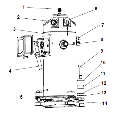
1)O-Ring (Unloader Connection)
2)Teflon Seal for Valve Connection (2)
3)Compressor
4)Power Cable Gasket, Ground Connection Screw
5)Power Cable Lubricant - Krytox (not shown)
6)Compressor Discharge Temperature Sensor
7)O-Ring (Economizer Connection)
8)Teflon Seal for Valve Connection (2)
9)Base Mounting Bolts
10)SST Washers
11)Resilient Mount
12)SST Washers
13)Mylar Washers
14)Wire Ties
- - - - -
Procedure:
1.Turn the unit ON and run it in full cool mode for 10 minutes.
NOTE: If the compressor is not operational, frontseat the suction service valve and discharge service valve and go to step 5 below.
2.Frontseat the liquid line service valve and allow the unit to pull-down to 0.1 kg/cm2 (1 psig).
3.Turn the unit Off “0” at the Start-Stop switch (ST), turn the unit circuit breaker (CB1) Off and disconnect power to the unit.
4.Frontseat the discharge service valve and suction service valve.
5.Remove all remaining refrigerant from the compressor using a refrigerant recovery system.
See Figure 7.4 for connection diagram.
6.Remove the compressor terminal cover, disconnect the ground wire and pull the cable plug from the compressor terminals. Install the terminal cover back after removing the power cable.
NOTE: Inspect the power cable (plug) terminals to ensure they are not deformed or have any signs of heat or arcing. If any damage is noted, replace the power cable.
7.Remove the Rotalock fittings from the suction service and discharge service connections, and uncouple the digital unloader valve (DUV) and economizer lines from the compressor.
8.Cut the dome temperature sensor (CPDS) wires. The replacement compressor comes with a CPDS already assembled.
9.Remove and save the compressor base mounting bolts. Discard the four top resilient mounts and washers.
10.Remove (slide out) the old compressor from the unit.
11.Inspect the compressor base plate for wear. Replace, if necessary.
12.Wire tie the compressor base plate to the compressor.
13.Slide the new compressor into the unit.
NOTE: DO NOT add any oil to the replacement compressor. Replacement compressor is shipped with a full oil charge of 60 oz.
14.Cut and discard the wire ties used to hold the base plate to the compressor.
15.Place the new SST washers on each side of the resilient mounts, and the new Mylar washer on the bottom of it as shown in Figure 7.8. Install the four base mounting bolts loosely.
16.Place the new Teflon seals at the compressor suction and discharge ports as well as the O-rings at the DUV and economizer line connection ports. Hand tighten all four connections.
17.Torque the four base-mounting screws to 6.2 mkg (45 ft-lbs).
18.Torque the compressor ports / connections.
|
Service Valve / Connection |
Torque Value |
|---|---|
|
Suction and Discharge Rotalocks |
108.5 to 135.5 Nm (80 to 100 ft-lbs.) |
|
Unloader connection |
24.5 to 27 Nm (18 to 20 ft-lbs.) |
|
Economized connection |
32.5 to 35 Nm (24 to 26 ft-lbs.) |
19.Connect (butt-splice and heat shrink) the new compressor dome temperature sensor with the old sensor wires removed in step 8. Wire-tie any loose wiring as appropriate.
20.Evacuate the compressor to 1000 microns if the unit was pumped down before the replaced compressor was removed. Otherwise, evacuate the complete unit and charge it with refrigerant.
See Section 7.1.9 for evacuation procedure.
See Section 7.1.7.2 for adding refrigerant charge procedure.
21.Open the compressor terminal cover and connect the compressor power cable following the steps below:
a.Liberally coat the orange gasket surfaces with the Krytox lubricant.
b.Install the orange gasket part onto the compressor fusite with the grooved or threaded side out. Ensure that the gasket is seated onto the fusite base.
c.Coat the inside of the power plug (female) connector pins with the Krytox lubricant, and insert the plug onto the compressor terminal connections. Make sure the orange gasket has bottomed out onto the fusite and fits securely onto the terminal pins while fully inserted into the orange plug.
d.Connect the green ground wire to the grounding tab located inside the terminal box of the compressor using the self-tapping grounding screw. Close the compressor terminal box using the terminal cover removed in step 20.
22.Backseat all service valves, connect the power to the unit and run for at least 20 minutes.
23.Perform a leak check of the system. See Section 7.1.8 for procedure.
The high pressure switch (HPS), shown in Figure 3.25, monitors abnormally high discharge pressure. It opens at 25 (+/- 1.0) kg/cm2 | 350 (+/- 10) psig. It closes at 18 (+/- 0.7) kg/cm2 | 250 (+/- 10) psig.
NOTE: The HPS is not adjustable, it needs to be replaced if not operating properly.
7.3.1Checking the High Pressure Switch
1.Remove switch as outlined in Section 7.3.2.
2.Connect an ohmmeter or continuity light across switch terminals. An ohmmeter will indicate no resistance or continuity light will be illuminated if the switch closed after relieving compressor pressure.
3.Connect hose to a cylinder of dry nitrogen, as illustrated in Figure 7.9.
Figure 7.9 High Pressure Switch Testing with Nitrogen
1)Cylinder Valve
2)Cylinder Gauge
3)Pressure Regulator
4)Nitrogen Cylinder
5)Pressure Gauge
(0 to 36 kg/cm2 = 0 to 400 psig)
6)Bleed-Off Valve
7)1/4 inch Connection
- - - - -
Do not use a nitrogen cylinder if it does not have a pressure regulator.
4.Set the nitrogen pressure regulator at 26.4 kg/cm2 (375 psig) with the bleed-off valve closed.
5.Close the valve on the cylinder and open the bleed-off valve.
6.Open the cylinder valve. Slowly close the bleed-off valve to increase pressure on the switch. The switch should open at a static pressure up to at 25 (+/- 1.0) kg/cm2 | 350 (+/- 10) psig. If a light is used, the light will go out. If an ohmmeter is used, the meter will indicate an open circuit.
7.Slowly open the bleed-off valve to decrease pressure. The switch should close at 18 (+/- 0.7) kg/cm2 | 250 (+/- 10) psig.
7.3.2Replacing the High Pressure Switch
1.Remove the refrigerant charge.
2.Disconnect wiring from defective switch. The high pressure switch (HPS) is located on the discharge connection or line and is removed by turning counterclockwise.
3.Install a new HPS after verifying switch settings.
4.Evacuate, dehydrate and recharge the system. See Section 7.1.9 for procedure.
5.Start the unit, verify refrigeration charge and oil level.
7.4Condenser Coil
The condenser coil consists of a series of parallel copper tubes expanded into copper fins and formed into a “U” shape with the fourth side of the square formed by the support bracket.
7.4.1Cleaning the Condenser Coil
To ensure optimal efficiency of the unit, the condenser coil must be clean. The condenser coil should be cleaned at least once a year, but more frequent cleaning may be required depending on operating conditions. The coil is cleaned with fresh water sprayed in the reverse direction of the air flow to remove any debris from the coil. A high pressure washer is not required, mains water pressure is sufficient.
Before servicing the unit, make sure the circuit breakers (CB1 & CB2) and start-stop switch (ST) are in the OFF position and the unit is disconnected from power.
1.Make sure the unit is powered off and the plug is disconnected.
2.Remove the condenser fan grille.
3.Starting from the top of the coil, use a water hose with a nozzle to wash the coil from the inside out.
4.Systematically wash across the inside top face of the coil until the water runs clean.
5.Wash down the center section, then through the bottom of the coil. Continue washing until the water runs clear.
6.After the coil is clean, rinse the condenser fan to remove any dirt build up from the blades.
7.Replace the condenser fan grille ensuring that it is centered around the fan.
7.4.2Removing the Condenser Coil
1.Connect a manifold gauge set to a refrigerant recovery system (blue hose), electronic micron gauge (red hose) and a vacuum pump (yellow hose). Then, connect the suction service valve, discharge valve and liquid line service valve to the vacuum pump with service hoses suitable for evacuation.
See Figure 7.4 for connection diagram.
1.Remove all refrigerant using the refrigerant recovery system. First recover liquid refrigerant from the receiver. Then, finish the recovery procedure in vapor mode.
Before servicing the unit, make sure the circuit breakers (CB1 & CB2) and start-stop switch (ST) are in the OFF position and the unit is disconnected from power.
2.Remove the condenser fan grille. Retain all bolts and washers for reuse.
3.Remove the condenser fan.
4.Remove the infill panels to the left and right of the condenser fan shroud.
5.Remove the condenser fan shroud.
6.Unplug the condenser fan motor.
7.Remove and retain sufficient putty from around the motor wire harness to allow the harness to be slid back through the side support bracket.
8.Cut the top and bottom drain lines midway between the side support bracket and the first cable tie, approximately 150mm (6”) from the side support bracket.
9.Remove and retain sufficient putty from around the drain lines to allow the tubes to be slid back through the side support bracket.
10.Remove the filter drier.
11.Unbraze the inlet connection to the coil.
12.Remove the cushion clamps securing the liquid line to the top and bottom receiver brackets. Retain all clamps and securing hardware.
13.Place a support under the condenser coil before releasing the coil from the frame.
14.Remove the lower mounting bracket bolts from the inside of the coil.
15.Remove the top mounting bracket bolts and grille extension mount from inside the coil.
16.Remove the side support bracket mounting bolts.
17.Slide the condenser assembly with the receiver out of the unit.
7.4.3Preparing the Condenser Coil
Before installing the new condenser coil, the receiver assembly and mounting hardware must be removed from the old coil assembly.
1.From the old coil, unbolt the receiver assembly from the side support bracket.
2.Unbraze the receiver assembly from the coil outlet line and remove from the coil assembly.
3.Unbolt the side support bracket from the top and bottom coil supports and remove from the old coil.
4.Refit the side support bracket to the new coil ensuring that the top and bottom are flush mounted with the coil support.
7.4.4Installing the Condenser Coil
Once the side support bracket has been secured to the new condenser coil, the entire assembly is ready to be installed into the unit.
1.Slide the new condenser coil into place ensuring the coil inlet connection is mated to the pipework and that the coil is fully supported.
2.Secure the condenser coil into the unit using the retained hardware; refit the mylar and fender washers:
a.Refit the side support bracket bolts.
b.Refit the top support bracket bolts as well as the top grille extension support.
c.Refit the bottom support bracket bolts.
3.Braze the condenser coil inlet connection.
4.Insert the receiver pipe work onto the coil outlet and loosely secure the receiver assembly to the side support bracket with the retained hardware.
5.Braze the outlet connection to the receiver assembly.
6.Install a new filter drier.
7.Replace the liquid line cushion clamps.
8.Secure the receiver assembly to the side support bracket.
9.Pressure / leak test the coil and filter drier connections. See Section 7.1.8.
10.Evacuate the entire unit. See Section 7.1.9.
11.Slide the top and bottom drain lines back into place through the side support bracket.
12.Using the two supplied straight connectors and contact adhesive, reconnect the drain lines.
13.Slide the condenser fan motor wiring harness back through the side support bracket and refit to the condenser motor.
14.Replace all wire ties that were removed to properly secure the drain line and wiring.
15.Reseal the wire harness and drain line penetrations with the putty.
16.Slide the condenser fan onto the motor shaft reversed but do not secure.
17.Refit the condenser fan shroud to the unit. Use the condenser fan as a guide to ensure the shroud is properly centered around the fan.
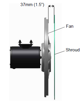
18.Remove the condenser fan, and place it on the shaft facing the correct direction. Adjust the fan to the correct position, 37mm (1.5”) from the fan shroud, see Figure 7.10.
Figure 7.10 Condenser Fan Position
19.Use Loctite “H” on the fan set screws, and tighten.
20.Refit the left and right infill panels.
21.Refit the condenser fan grille, ensuring the grille is properly centered around the condenser fan.
22.Evacuate the entire unit. See Section 7.1.9.
23.Recharge the unit with the charge shown on the unit serial plate. See Section 7.1.7. It is important for proper unit operation that the charge is weighed into the unit.
7.5Condenser Fan and Fan Motor
The condenser fan rotates counter-clockwise (viewed from front of unit). The fan pulls air through the condenser coil, and discharges the air horizontally through the front of the unit.
7.5.1Removing and Replacing the Condenser Fan Motor
Before servicing the unit, make sure the circuit breakers (CB1 & CB2) and start-stop switch (ST) are in the OFF position and the unit is disconnected from power.
1.Remove the condenser fan grille. Retain all bolts and washers for reuse.
2.Remove the condenser fan by loosening the two set screws.
3.Disconnect the condenser fan motor wiring.
Take necessary steps (place plywood over coil or use sling on motor) to prevent motor from falling into condenser coil.
4.Note the number of shims on each side of the motor. The same configuration is required to refit the new motor.
5.Remove the fan motor mounting hardware and remove the motor.
6.Loosely mount the new motor using new lock nuts.
7.Connect the fan motor wiring to the new fan motor.
8.Replace the shims in the same configuration as they were removed.
9.Tighten the fan motor mounting bolts to properly secure the motor.
10.To make sure that the motor is aligned properly, slide the condenser fan onto the motor shaft reversed but do not secure.
11.Rotate the fan to make sure the fan blades do not contact the shroud.
If the fan motor is misaligned vertically, add or remove shims to align.
If the fan motor is not properly centered, loosen the mounting bolts, and adjust the motor position on the bracket, and then secure the motor.
12.Remove the condenser fan, and connect the fan motor wiring to the fan motor.
13.Place the condenser fan on the shaft facing the correct direction. Adjust the fan to the correct position, 37mm (1.5”) from the fan shroud, see Figure 7.10.
14.Use Loctite “H” on the fan set screws, and tighten.
15.Refit the left and right infill panels.
16.Refit the condenser fan grille, ensuring the grille is properly centered around condenser fan.
7.6Water-Cooled Condenser Cleaning
The water-cooled condenser can accumulate rust, scale and slime on the water-cooling surfaces. This can interfere with the transfer of heat, reduce system capacity, cause higher head pressures and increase the load on the system.
By checking the leaving water temperature and the actual condensing temperature, it can be determined if the condenser coil is becoming dirty. A larger than normal difference between leaving condensing water temperature and actual condensing temperature, coupled with a small difference in temperature of entering and leaving condensing water, is an indication of a dirty condensing coil. If the water-cooled condenser is dirty, it may be cleaned and de-scaled.
Cleaning Supplies Needed:
•Oakite Aluminum Cleaner® 164, available as a powder in 20 kg (44 lb) pails and 205 kg (450 lb) drums.
•Oakite Composition No. 32, available as a liquid in cases, each containing 3.785 liters (4 U.S. gallon) bottles and also in carboys of 52.6 kg (116 lbs) net.
•Fresh clean water.
•Acid proof pump and containers or bottles with rubber hose.
NOTE: When Oakite Compound No. 32 is used for the first time, contact a local Oakite technical service representative for suggestions in planning the procedure.
7.6.1Cleaning Procedure Summary
1.Turn the unit off and disconnect main power.
2.Disconnect the water pressure switch tubing by loosening the two flare nuts. Install a 1/4 inch flare cap on the water-cooled condenser inlet tube (replaces tubing flare nut). De-scale tubing if necessary.
3.Drain water from the condenser tubing circuit.
4.Clean the water tubes with Oakite Aluminum Cleaner® 164 to remove mud and slime.
5.Flush.
6.De-scale the water tubes with Oakite No. 32 to remove scale.
7.Flush.
8.Neutralize.
9.Flush.
10.Put the unit back in service under normal load and check head (discharge) pressure.
7.6.2Cleaning Procedure Detailed
1.Drain and flush the water circuit of the condenser coil. If scale on the tube inner surfaces is accompanied by slime, a thorough cleaning is necessary before de-scaling process can be accomplished.
2.To remove slime or mud, use Aluminum Cleaner® 164. Mix 170 grams (6 ounces) per 3.785 liters (1 U.S. gallon) of water. Mix cleaner in one half the volume of water, while stirring, and then add remaining water. Warm this solution and circulate through the tubes until all slime and mud has been removed.
3.After cleaning, flush the tubes thoroughly with fresh clean water.
4.Prepare a 15% by volume solution for de-scaling, by diluting Oakite Compound No. 32 with water. Do this by slowly adding 0.47 liter (1 U.S. pint) of the acid (Oakite No. 32) to 2.8 liters (3 U.S. quarts) of water.
Oakite No. 32 is an acid. Be sure that the acid is slowly added to the water. DO NOT PUT WATER INTO THE ACID - this will cause spattering and excessive heat.
Wear rubber gloves and wash the solution from the skin immediately if accidental contact occurs. Do not allow the solution to splash onto concrete.
5.Fill the tubes with this solution by filling from the bottom.
NOTE: It is important to provide a vent at the top for escaping gas.
6.Allow the Oakite No. 32 solution to soak in the tube coils for several hours, periodically pump-circulating it with an acid-proof pump.
An alternate method may be used whereby a pail, filled with the solution and attached to the coils by a hose can serve the same purpose by filling and draining. The solution must contact the scale at every point for thorough de-scaling. Air pockets in the solution should be avoided by regularly opening the vent to release gas. Keep flames away from the vent gases.
7.The time required for de-scaling will vary, depending upon the extent of the deposits. One way to determine when de-scaling has been completed is to titrate the solution periodically, using titrating equipment provided free by the Oakite technical service representative. As scale is being dissolved, titrate readings will indicate that the Oakite No. 32 solution is losing strength. When the reading remains constant for a reasonable time, this is an indication that scale has been dissolved.
8.When de-scaling is complete, drain the solution and flush thoroughly with water.
NOTE: If condenser cooling water is not being used as drinking water or is not re-circulated in a closed or tower system, neutralizing is not necessary.
9.Following the water flush, circulate a 56.7 gram (2 ounce) per 3.785 liter (1 U.S. gallon) solution of Oakite Aluminum Cleaner® 164 through the tubes to neutralize. Drain this solution.
10.Flush the tubes thoroughly with fresh water.
11.Put the unit back in service and operate under normal load. Check the head pressure. If normal, a thorough de-scaling has been achieved.
7.7Filter Drier
As a general practice the filter drier, shown in Figure 3.12, should be replaced any time the system is opened for service. On units equipped with a water-cooled condenser, if the sight glass appears to be flashing or bubbles are constantly moving through the sight glass, the unit may have a low refrigerant charge or the filter drier may be partially plugged.
7.7.1Checking the Filter Drier
1.Test for a restricted or plugged filter drier by feeling the liquid line inlet and outlet connections. If the outlet side feels cooler than the inlet side, then the filter drier should be changed.
2.Check the moisture-liquid indicator. If it shows a high level of moisture, the filter drier should be replaced.
7.7.2Replacing the Filter Drier
1.Pump down the unit. See Section 7.1.6 for procedure.
2.Replace the filter drier. Torque to 43-47 Nm (32-35 ft-lbs).
3.Evacuate the low side in accordance with Section 7.1.9, evacuation procedure.
4.After unit is in operation, inspect for moisture in the system and check the charge.
7.8Evaporator Coil
The evaporator coil should be cleaned regularly. The preferred cleaning fluid is fresh water or steam. Another recommended cleaner is Oakite 202 or similar, following manufacturer’s instructions. The two drain pan hoses are routed behind the condenser fan motor and compressor. The drain pan line(s) must be open to ensure adequate drainage.
7.8.1Replacing the Evaporator Coil
1.Pump down the unit. See Section 7.1.6 for procedure.
Before servicing the unit, make sure the circuit breakers (CB1 & CB2) and start-stop switch (ST) are in the OFF position and the unit is disconnected from power.
2.With power OFF and power plug removed, remove the screws securing the panel covering the evaporator section (upper panel).
3.Disconnect the defrost heater wiring.
4.Remove the mounting hardware from the coil.
5.Unsolder the two coil connections, one at the distributor and the other at the coil header.
6.Disconnect the defrost temperature sensor from the coil. See Section 7.22.
7.Remove middle coil support.
8.After defective coil is removed from unit, remove defrost heaters and install on replacement coil.
9.Install the coil assembly by reversing the above steps.
10.Leak check the connections. Evacuate and add refrigerant charge. See Section 7.1.9, evacuation procedure.
7.9Evaporator Heaters
The heaters, see Figure 7.11, are wired directly back to the contactor and if a heater failure occurs during a trip, the heater set containing that heater may be disconnected at the contactor. The next pre-trip (P1) will detect that a heater set has been disconnected and indicate that the failed heater should be replaced.
Figure 7.11 Heater Arrangement
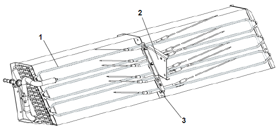
1)Heater Element (6)
2)Bracket
3)Retainer
- - - - -
7.9.1Megger Testing the Heaters
Before servicing the unit, make sure the circuit breakers (CB1 & CB2) and start-stop switch (ST) are in the OFF position and the unit is disconnected from power.
All of the checks performed during this procedure should be carried out using a 500v Meg-ohm tester.
1.Connect the ground wire from the insulation tester to a fixed ground point, preferably the ground plate in the control box.
2.At the load side of the heater contactor, check the insulation resistance to ground.
If readings are > 2 Mohm, then the heaters are operating properly and no action is needed.
If readings are < 1 Mohm, then the faulty heater needs to be identified. Proceed to step 3.
If readings are between 1 and 2 Mohm, then the heaters need to be re-tested with the following steps:
a.Reconnect the unit to power and power the unit on.
b.Set the unit set point to a minimum of 10°C higher than the current temperature of the container. Allow the unit to go into heat mode, reach the temperature setpoint and maintain for 10-15 minutes.
c.Power the unit off. Allow the unit to cool to ambient temperature.
d.Connect the ground wire from the insulation tester to a fixed ground point, preferably the ground plate in the control box.
e.At the load side of the heater contactor, check the insulation resistance to ground.
If readings are > 1 Mohm, then the heaters are operating properly and no action is needed.
If readings are < 1 Mohm, then the faulty heater needs to be identified. Proceed to step 3.
3.Identify the faulty heater(s):
a.Remove all six connections from the Heater (HR) contactor load side, which splits the six heaters into three separate pairs.
b.Identify the following three wires: DHTL, DHML, DHBL. There is one from each load connection.
c.Repeat the Megger test on each pair of heaters to identify the faulty heater pair. Connect the ground clip from the insulation tester to a fixed ground point on the unit, preferably the ground plate in the control box. Connect the test clip to one of the wires stated above.
d.Test all three wires and replace any heater pair that has readings < 1 Mohm.
4.If the unit is loaded, and the heater can not be immediately replaced, perform the following steps:
a.Identify the wire at the opposite end of the faulty heater pair: DHTL - DHTR, DHML - DHMR, DHBL - DHBR.
b.Isolate the two wires.
c.Reconnect the remaining good wiring pairs to their original connections.
d.The unit will fail the PTI test P1-0 at the next pre-trip inspection. Repair action can be taken at that time.
5.If the unit is empty, replace the faulty heater:
a.With the heater pair identified, remove the upper back panel inside the container.
b.Identify the center point connection for the heater pair (black wiring from heaters) either against the unit back wall or in the wiring loom.
c.Cut the splice to separate the two heaters.
d.Carry out a Megger check on the two heaters. Replace any heater where the Megger readings are < 1 Mohms. If all heaters are above the acceptable limit with the wiring disconnected, then this indicates that the fault was in one or more of the wire splices that were removed.
e.Remove the hold-down clamp securing the heater(s) to the coil.
f.Verify that the heaters are not hot before handling them.
g.Lift the bent end of the heater (with the opposite end down and away from the coil). Move the heater to the side enough to clear the heater end support and remove.
h.To install a heater, reverse steps.
i.Reconnect all wiring using new splices and heat shrink where needed. The heat shrink MUST have a 'meltable' liner to ensure that the connections are properly sealed when shrunk. This can be seen as a 'ring' of melt liner pushed from under the heat shrink at each end of the shrink tube.
NOTE: Failure to use melt liner heat shrink allows moisture to 'wick' up under the heat shrink and cause a leakage path.
7.10Evaporator Fan and Motor Assembly
The evaporator fans circulate air throughout the container by pulling air in at the top of the unit. The air is forced through the evaporator coil where it is either heated or cooled and then discharged out the bottom of the refrigeration unit into the container. The fan motor bearings are factory lubricated and do not require additional grease.
Figure 7.12 Evaporator Fan Assembly
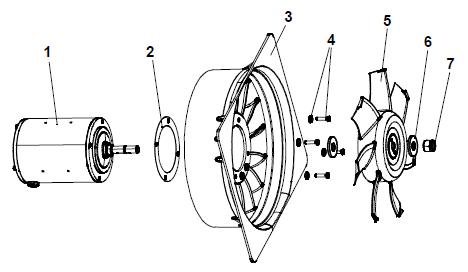
1)Motor
2)Protector
3)Stator
4)Screws / Washers
5)Fan
6)Washer
7)Nut
- - - - -
7.10.1Replacing the Evaporator Fan Assembly
Before servicing the unit, make sure the circuit breakers (CB1 & CB2) and start-stop switch (ST) are in the OFF position and the unit is disconnected from power.
1.Remove the access panel by removing the mounting bolts and TIR locking device.
2.Reach inside of the unit and remove the Ty-Rap securing the wire harness loop.
3.Disconnect the connector by twisting to unlock and pulling to separate.
4.Loosen the four 1/4-20 clamp bolts that are located on the underside of the fan deck at the sides of the fan assembly. Slide the loosened clamps back from the fan assembly.
5.Slide the fan assembly out from the unit and place on a sturdy work surface.
7.10.2Disassembling the Evaporator Fan Assembly
1.Attach a spanner wrench to the two 1/4-20 holes located in the fan hub. Loosen the 5/8-18 shaft nut by holding the spanner wrench stationary and turning the 5/8-18 nut counter-clockwise. See Figure 7.12.
2.Remove the spanner wrench. Use a universal wheel puller and remove the fan from the shaft. Remove the washers and key.
3.Remove the four 1/4-20 x 3/4 long bolts that are located under the fan that support the motor and stator housing. Remove the motor and plastic spacer.
7.10.3Assembling the Evaporator Fan Assembly
NOTE: When removing the black nylon evaporator fan blade, care must be taken to assure that the blade is not damaged. In the past, it was a common practice to insert a screwdriver between the fan blades to keep it from turning. This practice can no longer be used, as the blade is made up of a material that will be damaged. It is recommended that an impact wrench be used when removing the blade. Do not use the impact wrench when reinstalling, as galling of the stainless steel shaft can occur.
1.Assemble the motor and plastic spacer onto the stator.
2.Apply Loctite to the 1/4-20 x 3/4 long bolts and torque to 0.81 mkg (70 inch-pounds).
3.Place one 5/8 flat washer on the shoulder of the fan motor shaft. Insert the key in the keyway and lubricate the fan motor shaft and threads with a graphite-oil solution (such as Never-seez).
4.Install the fan onto the motor shaft. Place one 5/8 flat washer with a 5/8-18 locknut onto the motor shaft and torque to 40 foot-pounds.
5.Install the evaporator fan assembly in reverse order of removal. Torque the four 1/4-20 clamp bolts to 0.81 mkg (70 inch-pounds). Connect the wiring connector.
6.Replace the access panel making sure that the panel does not leak. Make sure that the TIR locking device is lock-wired. Torque the access panel hardware to 69 kg-cm (60 in/lbs.) using a crossing pattern as shown in Figure 7.13. Repeat the pattern twice for a proper seal.
Figure 7.13 Access Panel Torque Pattern
7.11Evaporator Section Cleaning
Containers and container units that are exposed to certain fumigants may develop visible surface corrosion. This corrosion will show up as a white powder found on the inside of the container and on the reefer unit evaporator stator and fan deck. Analysis by Carrier Transicold environmental specialists have identified the white powder as consisting predominantly of aluminum oxide, which is a coarse crystalline deposit most likely caused by surface corrosion on the aluminum parts within the container. If left untreated over time, it may build up in thickness and eventually flake as a lightweight white powder.
The surface corrosion of aluminum is caused by exposure to chemicals such as sulfur dioxide and possibly other fumigants that are commonly used for fumigation and protection of some perishable cargo such as grapes, for example. Fumigation is the process by which a chemical is released into an enclosed area to eliminate infestations of insects, termites, rodents, weeds and soil-born disease.
Typically any aluminum oxide that becomes detached from evaporator fan stators will be blown into the wet evaporator coil where it will be caught and then flushed out of the unit during routine defrost cycles. However, it is still highly recommended that after carrying cargo that is subject to fumigation procedures, that the inside of the unit be thoroughly cleansed prior to reuse.
Carrier Transicold has identified a fully biodegradable and environmentally safe alkaline cleaning agent (Tri-Pow’r® HD) for the unit. This will assist in helping to remove the corrosive fumigation chemicals and dislodging of the corrosive elements. This cleaner is available from the Carrier Transicold Performance Parts Group (PPG) and can be ordered through any of the PPG locations; Part Number NU4371-88.
As a general safety precaution, before using this product, refer to and retain the Material Safety Data (MSDS) sheet.
•Always wear goggles, gloves and work boots.
•Avoid contact with skin and clothing, and avoid breathing mists.
•When mixing, add water to the sprayer first, then the cleaner.
•ALWAYS provide for proper ventilation when cleaning indoor evaporator coils (rear doors must be open).
•Be aware of surroundings - food, plants, etc., and the potential for human exposure.
•Always read directions and follow recommended dilution ratios. More is not always better. Using non-diluted cleaner is not recommended.
1.Remove the upper evaporator access panel inside of the unit.
2.Spray the surface with water before applying the cleaning solution. This helps the cleaner work better.
3.Liberally apply the prepared cleaner solution (5 parts water and 1 part cleaner).
4.Allow the cleaner to soak in for five to seven minutes.
5.Assess area for rinsing. Follow all local regulations regarding disposal of waste water.
6.Thoroughly rinse the cleaner and surrounding area, floor, etc. When rinsing where heavy foaming solution is present, it is very important to take the time to thoroughly rinse the equipment and surroundings.
7.Always rinse the empty coil cleaner bottle, cap tightly and dispose of properly.
7.12Electronic Expansion Valve (EEV)
The electronic expansion valve (EEV), as shown in Figure 7.14, is an automatic device which maintains required superheat of the refrigerant gas leaving the evaporator. Unless the valve is defective, it seldom requires any maintenance. The valve functions are:
•Automatic response of refrigerant flow to match the evaporator load
•Prevention of liquid refrigerant entering the compressor.
NOTE: The EEV is independently operated by the microprocessor. See Section 8 for schematics.
Figure 7.14 Electronic Expansion Valve (EEV)
1)EEV Assembly
2)EEV
3)EEV Coil, with boot
4)Strainer
- - - - -
7.12.1Removing an EEV
Before servicing the unit, make sure the circuit breakers (CB1 & CB2) and start-stop switch (ST) are in the OFF position and the unit is disconnected from power.
1.Pump down the compressor. See Section 7.1.6 for pump down procedure.
2.Frontseat the suction service valve and discharge service valve.
3.Turn unit power off and remove power from the unit.
4.Remove the coil.
5.Remove the valve. The preferred method of removing the valve is to cut the connection between the brazed section and the valve, using a small tube cutter, then remove the valve. Alternatively, use a wet rag to keep the valve cool. Heat inlet and outlet connections to valve body and then remove the valve.
6.Clean the valve stem with mild cleaner, if necessary.
1.Install the valve and a new strainer with the cone of the strainer / screen pointing into the liquid line at the inlet to the valve.
2.During installation, make sure the EEV coil is snapped down fully, and the coil retention tab is properly seated in one of the valve body dimples. Also, ensure that coil boot is properly fitted over valve body.
3.Replace the filter drier. See Section 7.7.2 for replace procedure.
4.Evacuate to 500 microns by placing the vacuum pump on the liquid line and suction service valve.
5.Open the liquid line service valve and check refrigerant level.
6.Check superheat. It should be 4.4 to 6.7°C (8 to 12°F).
7.Check unit operation by running a Pre-Trip inspection. See Section 5.7 for pre-trip procedure.
7.13Economizer Solenoid Valve (ESV)
The economizer solenoid valve (ESV), as shown in Figure 3.23, opens when the unit is in Economized operation. The liquid refrigerant flows through the ESV to the expansion valve internal passages, absorbing heat from the liquid refrigerant flowing to the EEV. The resultant “medium” temperature / pressure gas enters the compressor at the economizer port fitting.
1.Pump down the compressor. See Section 7.1.6 for pump down procedure.
2.Frontseat the suction service valve and discharge service valve.
3.Remove the valve. The preferred method of removing the solenoid valve is to cut the connection between the brazed section and the valve, using a small tube cutter, then remove the valve. Alternatively, heat inlet and outlet connections to valve body and then remove the valve.
4.Clean the valve stem with mild cleaner, if necessary.
1.Fit the new solenoid valve into position and braze. Use a wet rag to keep the valve cool whenever brazing.
Before servicing the unit, make sure the circuit breakers (CB1 & CB2) and start-stop switch (ST) are in the OFF position and the unit is disconnected from power.
1.Turn unit power off and remove power from the unit. Disconnect leads.
2.Remove the top screw and o-ring.
3.Remove the coil and save mounting hardware, seals and spacer for reuse. See Figure 7.15.
Figure 7.15 Economizer Solenoid Valve (ESV) Coil Assembly
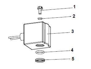
1)Slotted Screw
2)Top Coil (small) O-ring
3)Solenoid Coil, Tube and Body
4)Bottom Coil (large) O-ring
5)Brass Spacer
- - - - -
1.Install the brass spacer on the valve stem.
2.Lubricate both o-rings with silicone provided in the kit.
3.Install the bottom coil o-ring on the valve stem.
4.Install the solenoid coil on the valve stem.
5.Place the top coil o-ring on the coil mounting screw and secure the coil to the valve using a torque wrench. Torque the screw to 25 in-lbs.
6.Connect coil wires using butt-splices and heat shrink tubing.
7.14Economizer Expansion Valve (EXV)
The Economizer Expansion Valve (EXV), as shown in Figure 3.23, is an automatic device that maintains constant superheat of the refrigerant gas leaving at the point of bulb attachment, regardless of suction pressure. Unless the valve is defective, it seldom requires maintenance other than periodic inspection to ensure that the thermal bulb is tightly secured to the suction line and wrapped with insulating compound.
Before servicing the unit, make sure the circuit breakers (CB1 & CB2) and start-stop switch (ST) are in the OFF position and the unit is disconnected from power.
1.Pump down the compressor. See Section 7.1.6 for pump down procedure.
2.Frontseat the suction service valve and discharge service valve.
3.Turn unit power off and remove power from the unit.
4.Remove cushion clamps located on the inlet and outlet lines.
5.Remove insulation (Presstite) from the expansion valve bulb.
6.Unstrap the bulb, located on the economizer line.
7.Remove the valve. The preferred method of removing the valve is to cut the connection between the brazed section and the valve, using a small tube cutter. Remove valve. Alternatively, use a wet rag to keep valve cool. Heat inlet and outlet connections to valve body and remove valve.
8.Clean the valve stem with a mild cleaner, if necessary.
1.The Economizer Expansion Valve (EXV) should be wrapped in a soaked cloth for brazing.
2.Braze the inlet connection to the inlet line.
3.Braze the outlet connection to the outlet line.
4.Reinstall the cushion clamps on the inlet and outlet lines.
5.Replace the filter drier. See Section 7.7.
6.Evacuate to 500 microns by placing a vacuum pump on the liquid line and suction service valve.
7.Check EXV superheat. It should be 4.4 to 11.1°C (8 to 20°F).
7.15Digital Unloader Valve (DUV)
The normally closed digital unloader valve (DUV), as shown in Figure 3.20, will open during unloaded operation to allow pressure from the top of scroll elements to return to the suction service valve. A failed DUV can result in the unit running continually in the fully loaded mode causing it to undershoot its setpoint temperature.
NOTE: The DUV is independently operated by the microprocessor. See Section 8 for schematics.
Before servicing the unit, make sure the circuit breakers (CB1 & CB2) and start-stop switch (ST) are in the OFF position and the unit is disconnected from power.
1.Pump down the compressor. See Section 7.1.6 for pump down procedure.
2.Frontseat the suction service valve and discharge service valve. In the event the DUV is stuck open and the compressor cannot pump down, remove charge.
3.Turn unit power off and remove power from the unit.
4.Loosen the bolt on top of the DUV and remove the coil assembly.
NOTE: There is a small spacer tube between the top of the valve and the 12 VDC coil that needs to be reinstalled into the solenoid valve coil. When removing the coil, it may fall out when lifted from the valve body. Take care that the spacer is not lost; the valve will not function correctly without it.
5.Remove the clamps holding the DUV to the line.
6.Loosen the nuts securing the DUV in place.
7.Remove the valve. The preferred method of removing the solenoid valve is to cut the connection between the brazed section and the valve, using a small tube cutter, then remove the valve. Alternatively, use a wet rag to keep the valve cool. Heat the outlet connection to valve body and then remove the valve.
8.Examine the compressor and service valves. Ensure that the o-ring is not stuck in the gland of the valve.
9.Discard the o-ring on the o-ring face seal connection.
1.Lubricate the gland shoulder area and o-ring with refrigerant oil.
2.Fit the new valve in position and hand-tighten the o-ring nut.
3.Use a wet rag to keep the valve cool while brazing. Braze the DUV to the service valve connection.
4.Reinstall and tighten the brackets that secure the valve body to the line.
5.Torque the o-ring face seal connections to 18 to 20 ft-lbs.
6.Install the coil onto the valve body and tighten the attachment bolt.
NOTE: Confirm that the small spacer tube is inserted into the coil prior to attaching it to the valve body. The valve will not function correctly without it.
7.Leak check and evacuate the low side of unit as applicable.
8.Open the service valves.
7.16Digital Loader Valve (DLV)
PrimeLINE EDGE units (571-3xx models) have a normally closed digital loader valve (DLV), as shown in Figure 3.21. A DLV failure will result in the unit’s inability to cool due to a reduction in refrigerant flow.
Before servicing the unit, make sure the circuit breakers (CB1 & CB2) and start-stop switch (ST) are in the OFF position and the unit is disconnected from power.
1.Connect a manifold gauge set to a refrigerant recovery system (blue hose), electronic micron gauge (red hose) and a vacuum pump (yellow hose). Then, connect the suction service valve, discharge valve and liquid line service valve to the vacuum pump with service hoses suitable for evacuation.
See Figure 7.4 for connection diagram.
2.Remove all refrigerant using the refrigerant recovery system.
3.Turn unit power off and remove power from the unit.
4.Loosen the bolt on top of the DLV and remove coil assembly.
NOTE: There is a small spacer tube between the top of the valve and the 12 VDC coil that needs to be reinstalled into the solenoid valve coil. When removing the coil, it may fall out when lifted from the valve body. Take care that the spacer is not lost; the valve will not function correctly without it.
5.Remove clamps holding the DLV to the line.
6.Loosen the nuts securing the DLV in place.
7.Remove the valve. The preferred method of removing the solenoid valve is to cut the connection between the brazed section and the valve, using a small tube cutter, then remove the valve. Alternatively, use a wet rag to keep the valve cool. Heat the outlet connection to valve body and then remove the valve.
8.Examine the compressor and service valves. Ensure that the o-ring is not stuck in the gland of the valve.
9.Discard the o-ring on the o-ring face seal connection.
1.Power unit off and lock/tag out to prevent inadvertent power up.
2.Remove 8 bolts from guard under control box and remove guard.
3.Remove the digital unloader valve coil (DUV) and place a magnet tool on the valve to open it. If a magnet is not available perform the Jumper procedure:
a.Remove all 4 controller fuses (F1, F2, F3a, F3b).
b.Remove the wire from the KA6 connector on the front of the controller.
c.Disconnect the X1 wire from the 24VAC side of transformer (black wire) and locate it away for the transformer.
d.Jumper the black transformer wire to the KA6 wire removed from the connector.
e.Connect power to unit and turn circuit breaker on (DUV coil is now energized).
4.Connect a refrigerant recovery machine and recover refrigerant from the unit. (refer to the recovery machines Operation and Service manual for proper procedures).
5.If jumper procedure was used for the recovery, turn the circuit breaker off and disconnect the power. Follow the regional lock out tag out procedure for electrical.
6.Isolate valve by removing wire type wraps and conduit. Save any removed conduit for re-installation.
7.Remove top screw from the valve coil removing the coil and spacer. Ensure to retain the spacer as it is required for proper operation of the valve. Position coil away from valve body.
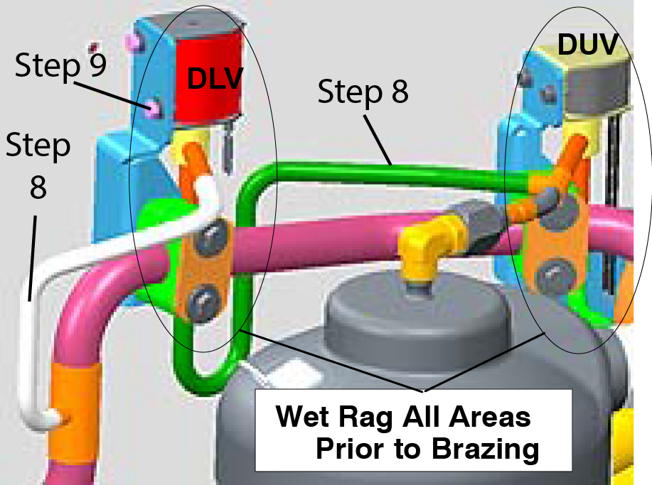
8.Using a tubing cutter cut the DLV refrigerant line as marked in Figure 7.16.
Figure 7.16 DLV Installation
9.Unbolt the valve from the mounting bracket and remove the valve assembly from the unit.
10.Clean pipework stubs on both unit and valve assembly in preparation for brazing.
11.Refit valve coil to the valve body ensuring the spacer ring is in place.
12.Slide new valve assembly into place, coupling the refrigerant lines.
13.Attach the solenoid coil to the mounting bracket of the new valve body and tighten.
14.Wet rag valve body and bracket mounting clamp. Failure to wet rag the body may result in the failure of the valve.
15.Using silver solder braze both bell connections.
16.Replace the filter drier.
17.With magnet still on the DUV stem, evacuate the compressor to 1000 Microns. If jumper procedure was used in step 3, reconnect unit to power and turn on the circuit breaker to again power the DUV.
18.On completion of the vacuum, remove the magnet and reinstall the DUV coil. If a jumper was used, turn off the circuit breaker and disconnect power. Remove jumper and reconnect the X1 wire to the black transformer wire. Reinstall and secure the KA6 wire to the KA plug at the controller.
19.Weigh the proper refrigerant charge into the unit as per the units operation and service manual and perform a leak check of the system.
20.Replace the guard under the control box.
21.If changed under the units warranty, tag part with unit information and cause of failure.
22.If possible collect unit data download for future failure analysis.
A Pre-Trip P6-7 test can check the operation of a digital unloader valve (DUV), or a digital loader valve (DLV) for PrimeLINE EDGE units (571-3xx models). When running the P6-7 test, the controller is looking for the differences in pressure and current draw between loaded mode and unloaded mode to make a judgment. If there are no differences, then it will show fail.
A failed DUV, which is normally closed, or an internal seal failure of the compressor can result in the unit running continually in the fully loaded mode causing it to undershoot its setpoint temperature.A failed DLV, which is normally closed, will result in the unit’s inability to cool due to a reduction in refrigerant flow
If the P6-7 test, fails, then refer to the following procedures to diagnose what component caused the test to fail.
Before servicing the unit, make sure the circuit breakers (CB1 & CB2) and start-stop switch (ST) are in the OFF position and the unit is disconnected from power.
7.17.1Troubleshooting for Standard Units (DUV Only)
1.Connect the manifold gauge set to the suction service valve and discharge service valve.
See Section 7.1.4.1 for connection procedure. See Figure 7.4 for connection diagram.
2.Front seat the suction service valve and pump down the compressor.
3.Front seat the discharge service valve to isolate the compressor.
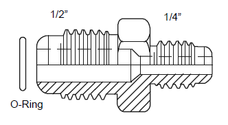
4.Disconnect the DUV from the top of compressor and install a 1/2 to 1/4” flared adapter and O-ring. See Figure 7.17 for illustration.
Figure 7.17 Adapter and O-Ring
5.Using refrigerant (R-134a or R-513A as specified for the unit model number) or nitrogen, pressurize the line to 50 psi (3.5 bar) at the adapter connection and close supply at the tank. Pressure should hold as the valve is normally closed. If pressure drops, check for leaks at the installed fitting (part number 40-50076-00sv); repair and retest. If pressure increases at the suction service valve and decreases at the pressure supply, the valve is leaking and should be replaced. If the valve is not leaking, proceed to step 6.
6.Energize the DUV by removing the coil and placing a magnet on the valve stem opening the valve. If the pressure does not increase at the suction service valve and decrease at the supply, replace the valve as it did not open.
If a magnet is not available, a jumper procedure can be used as follows:
a.Remove all four controller fuses (F1, F2, F3, F4).
b.Remove the KA6 wire from the KA controller connector on the front of the controller.
c.Disconnect the X1 wire from the 24VAC side of the transformer (black wire) and locate it away from the transformer.
d.Jumper between the black transformer wires to the KA6 wire removed from the connector.
e.Connect power to the unit and turn the circuit breaker on. The DUV coil is now energized. Pressure should drop.
f.Power the circuit breaker off, reconnect wires and reinstall fuses.
If the valve opens and closes properly, the failure mode is with the compressor and it should be changed at the earliest opportunity.
7.17.2Troubleshooting for EDGE Units (DUV/DLV)
1.Connect the manifold gauge set to the suction service valve and discharge service valve.
See Section 7.1.4.1 for connection procedure. See Figure 7.4 for connection diagram.
2.Use function code Cd41 Valve Override Controls to set an override to the DUV percentage (PCnt) value. Then, monitor compressor amperage and discharge pressure to determine which components has failed. See Section 7.18 for details on using Cd41.
Set the PCnt value at Cd41 to 100% and set the timer (tIM) to 5 minutes. This is a DLV Capacity Test. If the compressor is able to load, the compressor amperage (Cd03) and discharge pressure will increase and suction pressure will decrease; the DLV is working properly. If discharge pressure does not increase, the DLV should be replaced.
NOTE: The Digital Loader Valve Solenoid coil cycles: 0 to 0.6 amp DC (AC/DC current clamp).
Set the PCnt value at Cd41 to 20% and set the timer (tIM) to 5 minutes. This is a DUV Modulation Test. If the compressor is able to unload, the compressor amperage (Cd03) and discharge pressure drops and the suction pressure will rise; the DUV is working properly. If the discharge pressure does not decrease after the valve energizes, the DUV should be replaced.
NOTE: Unloader Valve Solenoid coil cycles: 0 to 0.4 amp AC (AC/DC current clamp).
Controller function code Cd41 is a configurable code that allows timed override operation of the automatic valves for troubleshooting. Test sequences are provided in Table 7–1. An event is posted when Cd41 is utilized. It is recommended to only override one valve at a time.
Valves that can be controlled:
•Digital Unloader Valve (DUV) Setting - open / close to various percentages. This is set at the PCnt sub menu.
•Electronic Expansion Valve (EEV) Setting - open / close to various percentages. This is set at the EEV sub menu.
•Economizer Solenoid Valve (ESV) Capacity - open / close in different operating configurations, see Table 7–1. This is set at the CAP sub menu.
The Override Timer (tIM) selection is provided to enter a time period of up to five minutes, during which the override(s) are active. This is set at the tIM sub menu.
•If the timer is active, valve override selections will take place immediately.
•If the timer is not active, changes will not take place until the timer is started.
•When the timer times out, the override function is automatically terminated and the valves return to normal machinery control.
Procedure to Perform a Valve Override:
1.Press the CODE SELECT key.
2.Use the Arrow keys until Cd41 is displayed in the left display, then press the ENTER key.
3.Press the ENTER key to go down the Cd41 menu selections. Or, press the CODE SELECT key to go back up through the menu selections. The menu items in order are:
•tIM - timer
•PCnt - Digital Unloader Valve (DUV) percentage
•EEV - Electronic Expansion Valve (EEV) percentage
•CAP - Electronic Solenoid Valve (ESV) standard or economized.
4.The standard practice is to override one valve at a time and observe. To do this, stop at a valve menu item (PCnt, EEV, or CAP) and use the Arrow keys to scroll through the choices available, as detailed in Table 7–1. Press ENTER to confirm the choice. If the selection is set to AUtO, no override action is taken.
5.Then, press the CODE SELECT key to navigate back to the tIM menu. Use the Arrow keys to select the desired time interval and press ENTER to confirm. The timer will start immediately and the valve override action chosen is executed. When the timer expires, the valve returns to normal machinery control.
Table 7–1 Cd41 Valve Override Control Menu
|
Settings (Right Display) |
|
|---|---|
|
tIM (Override Timer) |
0 minutes to 5 minutes in 30 second increments to |
|
PCnt Digital Unloader Valve (DUV) % Setting |
AUtO (Normal Machinery Control), 0, 3, 6, 10, 25, 50, 100 |
|
EEV Electronic Expansion Valve (EEV) % Setting |
AUtO (Normal Machinery Control) CLOSE (Closed) 0, 3, 6, 10, 25, 50, 100 |
|
CAP Economizer Solenoid Valve (ESV) |
AUtO (Normal Control) Std; UnLd (Economizer = Closed) ECOn (Economizer = Open) |
7.19Autotransformer
The optional Autotransformer, as shown in Figure 7.18, allows operation on 190/230, 3-phase, 50/60 Hz power. The autotransformer raises the supply voltage to the nominal 380/460 volt power required by the base unit.
Figure 7.18 Autotransformer
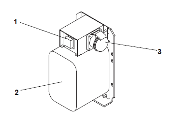
1)Circuit Breaker (CB2) 230-Volt
2)Dual Voltage Autotransformer
3)460 VAC Power Receptacle
- - - - -
If the Autotransformer unit does not start, check the following:
1.Verify the 460 VAC (yellow) power cable is plugged into the receptacle.
2.Verify that circuit breakers CB1 and CB2 are in the “ON” position. If the circuit breakers do not hold in, check voltage supply.
3.Using a voltmeter, and with the primary supply circuit ON, check the primary (input) voltage (460 VAC).
4.Next, check secondary (output) voltage (230 VAC). If output voltage is not available, the transformer is defective.
7.20Controller Service Procedures
A controller self diagnostic test can be performed with function code Cd74. While the test is running, “tESt” will flash on the display. Once the test is complete, the test result will be displayed. After 30 seconds, the controller returns to displaying the setpoint.
Do not remove wire harnesses from circuit boards unless you are grounded to the unit frame with a static safe wrist strap or equivalent static drain device.
Remove the controller module and unplug all connectors before performing any arc welding on any part of the container.
The guidelines and cautions provided herein should be followed when handling the modules. These precautions and procedures should be implemented when replacing a module, when doing any arc welding on the unit, or when service to the refrigeration unit requires handling and removal of a module.
1.Obtain a grounding wrist strap (Carrier Transicold P/N 07-00304-00) and a static dissipation mat (Carrier Transicold P/N 07-00277-00). The wrist strap, when properly grounded, will dissipate any potential static buildup on the body. The dissipation mat will provide a static-free work surface on which to place and/or service the modules.
2.Disconnect and secure power to the unit.
3.Place strap on wrist and attach the ground end to any exposed unpainted metal area on the refrigeration unit frame (bolts, screws, etc.).
4.Carefully remove the module. Do not touch any of the electrical connections if possible. Place the module on the static mat.
NOTE: The strap should be worn during any service work on a module, even when placed on the mat.
1.Disconnect all front wire harness connectors and move wiring out of the way.
2.The lower controller mounting is slotted. Loosen the top mounting screw, see Figure 4.1, and lift up and out.
3.Remove the module.
4.When removing the replacement module from its packaging, note how it is packaged. When returning the old module for service, place it in the packaging in the same manner as the replacement. The packaging has been designed to protect the module from both physical and electrostatic discharge damage during storage and transit.
1.Install the module by reversing the removal steps.
Torque values for mounting screws, see Figure 4.1, are 0.23 mkg (20 inch-pounds). Torque value for the connectors is 0.12 mkg (10 inch-pounds).
The Carrier rechargeable battery pack part # is 79-66081-20.
1.Turn the unit power Off and disconnect the power supply.
2.Open the control box door and remove both the high voltage shield and clear plastic rain shield (if installed).
3.Disconnect the battery connection at the BA connector and carefully remove wire ties along the battery wires leading back to the battery pack.
4.Using a driver bit, Carrier part number 07-00418-00, loosen the left hand screw on the battery pack cover then remove the second screw on the outer edge of the battery pack cover.
5.Remove the old battery from the bracket and assemble the new battery to the bracket.
6.Secure the battery wires from the battery along the previous route and then reconnect the BA connector. Heat shrink a ferrite clamp to the harness to reduce electromagnetic voltage transients onto this interface.
7.Replace wire ties that were removed. Replace shields and close the control panel door.
7.20.5AC Line Filter
There is an AC Line Filter installed between the Control Transformer and the PW Connector on the ML5 controller. This filter reduces electromagnetic voltage transients induced / coupled on to the 36 VAC Control Transformer secondary of the Transformer.
When the AC Line filter fails, 18 VAC will not be provided to the controller and the system will not power up. Checking for a nominal 36 VAC across the input and output of the filter will verify if the correct voltage is getting provided to the controller.
Apply power to the container, turn on the ST switch, and verify that 36 VDC is present across pins 1 and 3 on the AC Line Filter. Once input power is verified, check the power on the output of the filter on pins 2 and 4. Input and output voltages should match. If the control voltages so not match, or output power appears to be fluctuating, the filter capability of the power filter can be tested.
Power Filter Test
1.Disconnect power and lock out the container.
2.Remove the AC Power Filter from the system. Disconnect all spade connectors from the power filter, then remove the ground wire on the right side (line output) of power filter.
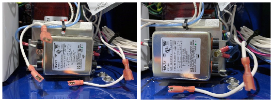
3.Remove the remaining mounting bolt on the left side (line input) and pull from the system control box.
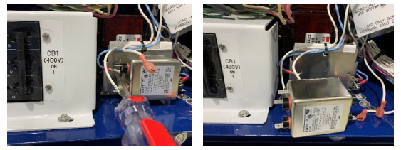
4.With the power filter removed, check for a capacitance reading of 0.54 uF +/-10% across pins 1 and 3. And then across pins 2-4.
5.Each individual pin can also be verified between the ground pin #5 and 1, 2, 3, 4. Testing each individual pin to the ground pin should read a capacitance of 0.011 uF +/-10%. Note that meter to left reading in nF but passing value 0.01052 uF.
6.Final check on the power filter is to verify the discharge resistor on the power filter output. Check resistance between pins 2 and 4 on the load side of the power filter for 330kΏ +/- 10%.
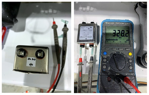
7.Reinstall the power filter. Install the right side of the power filter to the bracket with ground leads.Then, install the mounting screw on the right side of the power filter.
8.Connect wires to the power filter using the hot stamping on the wire harness and pin marking on the power filter.
|
Line or Load |
Wire |
Filter |
|---|---|---|
|
Line |
PF5-TRX2 to |
Pin 5 |
|
Line |
PF3-TRX3 to |
Pin 3 |
|
Line |
PF1-TRX4 to |
Pin 1 |
|
Load |
ST5-PF2 to |
Pin 2 |
|
Load |
ST2-PF4 to |
Pin 4 |
Power Filter Emergency Bypass Procedure
1.Connect the following with a 7.5 Amp automotive type fuse and cover the connections with electrical tape:
•PF1-TRX4 to ST5-PF2
•PF3-TRX3 to STS2-PF4
7.21Controller Programming Procedures
Refer to the T-372PL parts manual for a list of available tools for interfacing with the ML5 controller.
Notes Regarding USB Devices:
•The USB must have an ML5 software file or ML5 configuration file on the root level. If not, the “SEt UP” menu will not be accessible from underneath the “USb” menu.
•If upgrading from version 6325 or less to 6326 or higher, both configuration files (cf5 and cf6) must be on the usb drive at the time of upload. After completing the upgrade, only the cf6 file is required for upload.
•If more than one configuration database file is on the USB device at the root level, then only the file with the latest date will be considered.
•During a programming procedure, if “no USb” is displayed, wait up to 15 seconds for this message to be replaced with a different message. If the “no USb” message continues, remove and insert the USB device.
7.21.1Downloading DataCORDER Data to a USB Device
1.Turn unit power on (“I”) at the Start-Stop switch (ST). Wait for controller information to be displayed.
2.Insert the Micro USB drive (part # 12-50173-00) into the controller micro USB port.
3.Press the ALT MODE key on the keypad.
4.Use the Arrow keys until “USb” is displayed, then press the ENTER key.
5.Use the Arrow keys until “dn LoAd” is displayed, then press the ENTER key.
6.The Download Menu is now displayed. The amount of free space available on the drive is displayed first. Use the Arrow keys to scroll down through the choices: ALL, trIP, 30dAy, 60dAy, 90dAy and 180.
7.Confirm the selection by pressing the ENTER key. The download starts.
8.When the download is complete, the display will show “dLOAd donE”.
9.Remove the USB flash drive from the USB port.
7.21.2Uploading Controller Software from a USB Device
Refer to Carrier’s YouTube Channel to watch a video of this procedure.
1.Turn unit power on (“I”) at the Start-Stop switch (ST). Wait for controller information to be displayed.
2.Insert the Micro USB drive (part # 12-50173-00), pre-loaded with controller software, into the controller Micro USB port.
3.Press the ALT MODE key on the keypad.
4.Wait for the display to show “USb” or use Arrow keys to show “USb”, then press the ENTER key.
5.Use the Arrow keys until “UP LoAd” is displayed, then press ENTER.
6.“LoAd XXXX” is now on the display. If more than one ML5 software revision file is on the USB flash drive at the root level, press the Arrow keys until the desired revision is displayed.
7.Press the ENTER key to load the software to the controller. The display will flash “LoAd SoFt”.
8.When “CAn PULL” and “USb noW” appears on the displayed, remove the USB drive from the port.
9.The display will flash “Pro SoFt”, then display “rE StArt” and “StArt UP” after that.
10.When the controller restarts, the following are displayed in order: the Unit ID (Cd40), software version (Cd18), configuration number (Cd20) and configuration file date. And finally the message “Pro donE”. The software has been loaded.
11.Bring up function code Cd 18 to confirm the correct software revision.
7.21.3Uploading a Software Configuration from a USB Device
Refer to Carrier’s YouTube Channel to watch a video of this procedure.
1.Turn unit power on (“I”) at the Start-Stop switch (ST). Wait for controller information to be displayed.
2.Insert the Micro USB drive (part # 12-50173-00), pre-loaded with software configuration files, into the controller Micro USB port. The software files will have an extension of .ml5.
3.Press the ALT MODE key on the keypad.
4.Wait for the display to show “USb” or use Arrow keys to show “USb”, then press the ENTER key.
5.Use the Arrow keys until “SEt UP” is displayed, then press the ENTER key.
6.Use the Arrow keys until “run COnFG” is displayed, then press the ENTER key.
7.The display module will go blank briefly and then display “571 XXX”.
8.Use the Arrow keys to scroll through the list to obtain the proper model number, then press ENTER. The model number can be found on the unit nameplate.
IMPORTANT:
For units with software 6320 or greater loaded, when model numbers 571-113 or 571-123 are chosen the left display will show “rU” “SurE” and the right display shows “yES”. This is an attempt to prevent users from installing a customer specific configurations which CAN NOT be changed once entered. Use the Arrow keys to toggle selection between “yES” and “nO” and press ENTER to confirm. If “yES” is selected, any attempt afterwards to load a different model number will result in a “LoAd bAd” message. If “nO” is selected, the display returns to the main configuration menu.
9.Once the model number is selected, the display will show the message “rE StArt” briefly, and then “StArt UP” while the controller restarts. Do not take action during this time.
10.When the controller restarts, the following are displayed in order: the Unit ID (Cd40), software version (Cd18), configuration number (Cd20) and configuration file date. Remove the USB drive from the port.
11.Bring up function code Cd20 to confirm that the correct model configuration was loaded. The model should match what is shown on the unit nameplate.
7.21.4Setting the Date and Time
1.Turn unit power on (“I”) at the Start-Stop switch (ST). Wait for controller information to be displayed.
2.Insert the designated USB flash drive into the controller micro USB port.
3.Press the ALT MODE key on the keypad.
4.Use the Arrow keys until “USb” is displayed, then press the ENTER key.
5.Use the Arrow keys until “SEt UP” is displayed, then press the ENTER key.
6.Use the Arrow keys until “SEt tIM” is displayed, then press the ENTER key.
7.The date values are displayed in YYYY MM-DD format. Configure the date using the keypad.
•The values will be edited from left to right: the year first (YYYY), then month (MM) and then day (DD).
•Press the Arrow keys to increase or decrease a date value.
•Press the ENTER key to confirm the date value being modified and bring up the next value for editing.
•Press the CODE SELECT key to return to the previous date value.
8.Once date editing is complete and the day (DD) value is selected, press the ENTER key.
9.The time values are now displayed in HH MM format. Configure the time using the keypad.
•The values will be edited from left to right: the hours first (HH), then minutes (MM).
•Press the Arrow keys to increase or decrease a time value.
•Press the ENTER key to confirm the time value being modified and bring up the next value for editing.
•Press the CODE SELECT key to return to the previous time value.
10.Once time editing is complete, with the minutes (MM) value active, press the ENTER key.
11.The display returns to the USb menu. The date and time will be committed when the ENTER key is pressed.
7.21.5Setting the Container ID
This procedure explains how to set the Container ID, which can be found in Function Code Cd40. See Section 4.2.2. The characters will be preset to the container ID of the box that the refrigeration unit was originally commissioned in. If no ID has been loaded, Cd40 will show dashes as the ID will be invalid.
1.Turn unit power on (“I”) at the Start-Stop switch (ST). Wait for controller information to be displayed.
2.Insert the USB flash drive into the controller micro USB port.
3.Press the ALT MODE key on the keypad.
4.Use the Arrow keys until “USb” is displayed, then press the ENTER key.
5.Use the Arrow keys until “SEt UP” is displayed, then press the ENTER key.
6.Use the Arrow keys until “SEt Id” is displayed, then press the ENTER key. The current ID is displayed.
7.Configure the Container ID using the keypad.
•The first four characters are Alpha type and the last seven are numeric.
•The character being modified will always be on the right most position on the display.
•Press the Arrow keys to scroll through the selectable characters available.
•Press the ENTER key to confirm the choice and shift the selected character one position to the left to modify the next character.
•Press the CODE SELECT key to shift the characters one position to the right (backspace) to modify the previous character.
8.When the last value of Container ID is entered, press the ENTER key to enter the information to the controller.
7.22Temperature Sensor Service
Service procedures for the following temperature sensors are provided in this section:
•Supply (STS / SRS)
•Return (RTS / RRS)
•Ambient (AMBS)
•Defrost (DTS)
•Evaporator (ETS)
•Compressor Discharge (CPDS).
7.22.1Preparing an Ice-Water Bath
The ice-water bath is a method for testing the accuracy of sensors by submerging the sensors in an insulated container with ice cubes or chipped ice, then filling voids between ice with water and agitating until mixture reaches 0°C (32°F) measured on a laboratory thermometer.
Notes:
•Wherever possible, use a thermometer that is regularly calibrated by an accredited test lab. Contact your instrument representative if the reference thermometer is not showing correct readings.
•Always use a temperature measurement reference instrument which is of higher accuracy than the device checked – for e.g., a thermometer with a rated accuracy of +/- 0.2 °C should be used to check a device with a rated accuracy +/- 0.3 °C.
•A thermally insulated container, tub open to atmosphere and large enough to contain crushed ice and water should be used. The tub should be large enough to contain the unit’s sensor and the reference thermometer.
•Enough distilled water should be available to make ice cubes and to set up a proper and stable ice-water triple-point mixture. Prepare ice using distilled water.
•Pre-cool distilled water for testing.
Procedure:
1.Prepare a mixture of clean ice using distilled water in a clean insulated container. If possible, the person handling should be wearing latex gloves.
a.Crush or chip the ice to completely fill the container. Finer ice particles will produce a more accurate mixture.
b.Add enough pre-cooled distilled water to fill the container.
c.Stir the mixture for a minimum of 2 minutes to ensure water is completely cooled and mixture is good.
d.The mixture should generally contain about 85% ice with distilled water occupying the rest of the space.
e.Add more ice as the ice melts.
2.Stir the ice water slurry mixture to maintain a temperature 0°C (32°F).
3.Constantly monitor the temperature of the ice water slurry with your reference thermometer. Ensure that the temperature of the bath has stabilized. The criterion for stability generally is to take two readings at 1 minute intervals, and the two readings should give you 0°C (32°F).
7.22.2Sensor Checkout Procedure - Ice-Water Bath
This procedure is to verify the accuracy of a temperature sensor by placing in an ice-water bath.
1.Remove the sensor and place in a 0°C (32°F) ice-water bath. See Section 7.22.1 for procedure.
2.Start the unit and check the sensor reading on the control panel. Readings should be 0°C (32°F).
If the reading is correct, reinstall the sensor. If the reading is incorrect, continue with the next step.
3.If the reading is off slightly, then re-calibrate. If the reading is not within 0°C (32°F) +/- 0.25 degrees, replace the sensor and re-check.
7.22.3Sensor Checkout Procedure - Control Box
A sensor can be tested from the control box by utilizing the controller harness tool, see Figure 7.19, part # 76-50256-00. This tool reduces the risk of damaging the controller pins when probing the system harness. This procedure is described in detail in TechLINE article TL004-2022.
Figure 7.19 Controller Harness Tool
1.Remove power from the unit and follow lockout / tagout regulations.
2.Disconnect the harness from the ML5 controller and install the harness tool.
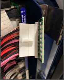
3.Locate the proper wires to be ohmed by referring to the system schematic.
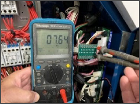
4.Check against the temperature resistance chart provided in Table 7–2 and Table 7–3.
7.22.4Supply and Return Sensor Calibration - GDP
European Commission GDP (Good Distribution Practices) guidelines, used worldwide, call for the equipment that controls or monitor environments where medicinal products are stored or transported be calibrated in accordance with pharmaceutical shipper specifications, typically every six months or annually.
This procedure explains how to perform a GDP calibration of the supply (STS / SRS) and return (RTS / RRS) sensors using DataLINE software version 3.1 or higher. The calibration procedure should be conducted in pairs (STS / SRS, or RTS / RRS) and it is recommended to calibrate before the full pre-trip inspection.
Before removing the Supply or Return air sensors from the unit, turn the ON/OFF switch and circuit breaker to the OFF position. Disconnect the power plug from the unit. Follow proper lockout/tagout procedures to ensure the power cannot inadvertently be energized. It is important that all dismantling work is done and tools and personnel are away from the unit before powering on the unit for calibration.
When performing the Return Air Sensor calibration, disconnect both evaporator motors.
NOTE: Before proceeding with the calibration procedure, ensure that controller software version is 5368 or higher and DataLINE version 3.1 or higher is installed onto the download device. Only the latest DataLINE and controller software will allow users to carry out Good Distribution Practice (GDP) calibration. Do not downgrade the software after installing the latest software.
NOTE: Before proceeding with the calibration procedure, it is recommended to check the sensors by running pre-trip P5-0. This test checks the sensor values. If the test fails, identify and correct the faulty sensor and run the test again.
Tools Required:
•Socket screwdrivers set
•Phillips screwdriver
•Standard hand tools
•Interrogator cable
•Laptop with DataLINE 3.1 or above installed
•Clean insulated container for distilled water and ice
•A regularly calibrated reference thermometer, recommended to be of accuracy up to 2 decimal places.
GDP Calibration, Removing Supply Sensors (STS / SRS) from Unit:
1.Locate the supply sensors cover assembly on the suction side of the compressor. Remove the two fasteners securing the cover of the sensors.
Remove the cover and rotate the supply air sensors, STS / SRS, in a clockwise direction and remove the sensors from the sensor housing.
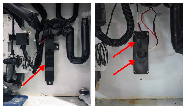
GDP Calibration, Removing Return Sensors (RTS / RRS) from Unit:
1.Remove both front access panels from the unit by removing 8 fasteners from each panel. Save all hardware for re-installation.
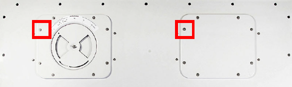
2.On the right side, disconnect the fan motor wiring, loosen the fastener and remove (slide) the evaporator motor from the unit.
3.Loosen the fastener on the sensor bracket.
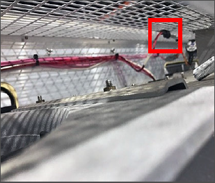
4.Cut all the wire ties that are securing the sensors to the harness and remove sensor.
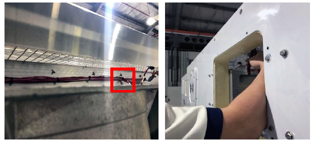
GDP Calibration, Perform Calibration:
Before powering on the unit, it is important to ensure that all dismantling work is done and tools are away and service personnel are not working on the unit at the time of power on.
1.Connect the interrogator cable to the interrogator port. Then, power on the unit.
2.From DataLINE or ContainerLINK application, open the Probe Calibration screen. If a pop-up window appears reminding the user to ensure proper ice bath temperature, click OK to acknowledge.
3.On the Probe Calibration screen, click on the Calibrate Supply Sensors or Calibrate Return Sensors button.
4.A Location of Service pop-up window will appear. In the appropriate fields, enter the Service Center Name and Service Center Location where the calibration is being performed. Then, click the Save button. If a pop-up window appears reminding the user to ensure proper ice bath temperature, click OK to acknowledge and remember to maintain the Ice bath at 0°C (32°F).
5.Prepare the ice-water bath. See Section 7.22.1 for Ice Bath Preparation procedure.
6.Place the ice bath in a location near sensors. For Return Sensors, place the ice bath on an elevated platform or ladder of appropriate height.
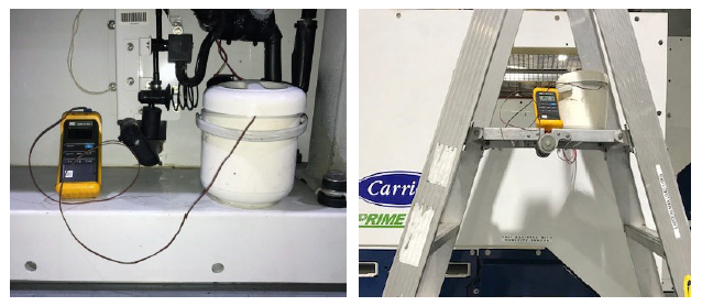
7.Once temperature stability is ensured, submerge the sensors in the ice water slurry. Make certain that the sensors do not contact the container sides or bottom, or each other. Continuously stir the slurry mixture during calibration.
8.Ensure that the Ice bath is at 0°C (32°F) using the calibrated reference thermometer. Make sure the thermometer is regularly maintained and cleaned.
Confirm that the sensor readings have stabilized and the sensors are within +/- 0.3°C (0.5°F). The readings can be taken from the Uncalibrated column in the Current Probe Offset Temperatures table.
9.After confirming the sensor readings have stabilized, click on the Start Calibration button. The process begins automatically and will complete in less than 5 minutes. Continue to stir the ice bath during the testing. Calibration fails if stability cannot be achieved or sensor offset is greater than 0.3°C (0.5°F).
10.Once the calibration has completed, a pop-up will appear with the message Calibrate Complete. Click OK to acknowledge and the results will then be displayed on the screen in the Results column. If the sensor can not pass calibration, then see Section 7.22.6 for sensor replacement procedures.
11.After completing the calibration, download a DCX file and check that all of the following event information is captured: service center name, location, the results of the calibration and the offset applied. The event is considered a success when all the intended sensors in calibration have passed.
Sustained cold temperature has been employed as a post-harvest method for the control of fruit flies and other insect genera. The commodity, insect species, treatment temperatures and exposure times are found in sections T107, T108, and T109 of the USDA Treatment Manual. In response to the demand to replace fumigation with this environmentally sound process, Carrier has integrated Cold Treatment capability into its microprocessor system. These units have the ability to maintain supply air temperature within one quarter degree Celsius of setpoint and record minute changes in product temperature within the DataCORDER memory, thus meeting USDA criteria.
A special type of recording is used for USDA cold treatment purposes. Cold treatment recording requires three remote temperature probes be placed at prescribed locations in the cargo. Provision is made to connect these probes to the DataCORDER via receptacles located at the rear left-hand side of the unit. Four or five receptacles are provided. The four 3-pin receptacles are for the probes. The 5-pin receptacle is for the Interrogator. The probe receptacles are sized to accept plugs with tri-cam coupling locking devices. A label on the back panel of the unit shows which receptacle is used for each probe.
The standard DataCORDER report displays the supply and return air temperatures. The cold treatment report displays USDA #1, #2, #3 and the supply and return air temperatures. Cold treatment recording is backed up by a battery so recording can continue if AC power is lost.
USDA Cold Treatment Procedure:
The following is a summary of the steps required to initiate a USDA Cold Treatment.
1.From the DataLINE or ContainerLINK application, navigate to the DataCorder Configuration screen. In DataLINE this is found under System Tools. In ContainerLINK this is found under System Configuration.
2.Verify that the DataCORDER is configured as follows and then close all screens when finished:
•Configuration Option is set for USDA probes
•Logging interval is set for 60 minutes.
•DataCorder Sample Type is set to 2 Averaged 3-USDA.
•Resolution is set to Normal.
3.Prepare a proper ice bath and ensure that it has stabilized at 0°C (32°F) using a calibrated reference thermometer. See Section 7.22.1 for Ice Bath Preparation procedure.
4.Submerge the sensors in the ice bath. Make certain that the sensors do not contact the container sides or bottom, or each other. Continuously stir the slurry mixture during calibration.
5.Navigate to the Probe Calibration screen in DataLINE or ContainerLINK. By default the screen should have the Auto Calibration option chosen. Click on Auto if it is not already selected. For Auto Calibration, the controller calculates the offsets for all probes using an assumed ice-bath temperature of 0.0°C (32°F).
6.Confirm that the sensor readings have stabilized and the sensors are within +/- 0.3°C (0.5°F). The readings can be taken from the Uncalibrated column in the Current Probe Offset Temperatures table.
7.After the sensor readings have stabilized, click the Start Calibration button. Probes are calibrated individually once they are determined to be stable. This calibration generates the probe offsets which are stored in the controller and applied to the USDA sensors for use in generating sensor type reports.
8.Pre-cool the container to the treatment temperature or below.
9.Install the controller battery pack (if not already installed). Then, check the battery status at code Cd19.
a.Press the CODE SELECT key on the display.
b.Use the Arrow keys to bring up Cd19 and press the ENTER key.
c.Use the Arrow keys to select bTEST and press the ENTER key. Refer to Cd19 description for more details and testing the battery
10.Place the three probes. Refer to the USDA Treatment Manual for directions on placement of probes in fruit and probe locations in container.
•Sensor 1: Place USDA 1 in a box at the top of the stack of fruit nearest to the air return intake.
•Sensor 2: Place USDA 2 slightly aft of the middle of the container, halfway between the top and bottom of the stack.
•Sensor 3: Place USDA 3 one pallet stack in from the container doors, halfway between the top and bottom of the stack.
11.Navigate to the ISO Trip Header screen to enter ISO Header information and a header comment if desired. Close the screen when finished. In DataLINE, this is found under System Tools. In ContainerLINK this is found under System Configuration.
12.Click the Start New Trip button to perform a Trip Start.
13.Bring up Code Cd51 on the unit display, enable Automatic Cold Treatment (ACT) and configure as required. See Section 5.9.4 for procedure.
Before servicing the unit, make sure the circuit breakers (CB1 & CB2) and start-stop switch (ST) are in the OFF position and the unit is disconnected from power.
NOTE: Include white date code label when cutting out and removing defective sensors. The label could be required for warranty returns.
NOTE: The P5 Pre-Trip test must be run to deactivate probe alarms. See Section 5.7.
1.Place the Start-Stop switch (ST) to “0” to turn the unit Off. Disconnect the power supply.
2.Cut the cable. Slide the cap and grommet off the bulb type sensor and save for reuse. Do not cut the grommet.
3.Cut one wire of existing cable 40 mm (1-1/2 inches) shorter than the other wire.
4.Cut the replacement sensor wires (opposite colors) back 40 mm (1-1/2 inches). See Figure 7.20.
Figure 7.20 Sensor Types
5.Strip back insulation on all wiring 6.3 mm (1/4 inch).
6.Slide a large piece of heat shrink tubing over the cable, and place the two small pieces of heat shrink tubing, one over each wire, before adding crimp fittings as shown in Figure 7.21.
Figure 7.21 Sensor and Cable Splice
1)Sensor (typical)
2)Large Heat Shrink Tubing (1)
3)Cable
4)Heat Shrink Tubing, 2 or 3 as required
- - - - -
7.If required, slide the cap and grommet assembly onto the replacement sensor.
8.Slip crimp fittings over dressed wires (keeping wire colors together). Make sure wires are pushed into crimp fittings as far as possible and crimp with crimping tool.
9.Solder spliced wires with a 60% tin and 40% lead Rosincore solder.
10.Slide heat shrink tubing over each splice so that ends of tubing cover both ends of crimp as shown in Figure 7.21.
11.Heat tubing to shrink over splice. Make sure all seams are sealed tightly against the wiring to prevent moisture seepage.
Do not allow moisture to enter wire splice area as this may affect sensor resistance.
12.Slide large heat shrink tubing over both splices and shrink.
13.Position sensor in unit as shown in Figure 7.21 and re-check sensor resistance:
For Supply Sensor,. see Figure 7.22; For Return Sensor, see Figure 7.23; For ETS Sensor, see Figure 7.24
14.Reinstall sensor. Refer to:
For Supply Sensor, see Section 7.22.7; For Return Sensor, see Section 7.22.8. For Defrost Temperature Sensor, see Section 7.22.9; For Evaporator Temperature Sensor, see Section 7.22.10.
7.22.7Installing a Supply Sensor (STS / SRS)
To properly position a unit Supply Temperature or Supply Recorder sensor (STS / SRS), the sensor must be fully inserted into the probe holder. This positioning will give the sensor the optimum amount of exposure to the supply air stream, and will allow the Controller to operate correctly. Insufficient probe insertion into the probe holder will result in poor temperature control due to the lack of air flow over the sensor.
It is also necessary to ensure that the probe tip does not contact the back panel. The design minimum clearance of 6 mm (1/4 inch) should be maintained. See Figure 7.22.
Figure 7.22 Supply Sensor (SRS / STS) Positioning
1)Sensor Wire
2)Cap & Grommet Assembly
3)Probe Holder
4)Evaporator Back Panel
5)Supply Sensor
- - - - -
7.22.8Installing a Return Sensor (RTS / RRS)
Reinstall the Return Temperature or Return Recorder sensor (RTS / RRS), as shown in Figure 7.23. For proper sensor placement, position the enlarged positioning section of the sensor against the side of the mounting clamp.
Figure 7.23 Return Sensor (RRS / RTS) Positioning
1)Mounting Clamp
2)Return Sensor
- - - - -
7.22.9Installing a Defrost Temperature Sensor (DTS)
The Defrost Temperature Sensor (DTS) must have insulating material placed completely over the sensor to ensure the coil metal temperature is sensed.
7.22.10Sensor (Installing an Evaporator Temperature ETS1 / ETS2)
The evaporator temperature sensors, ETS1 and ETS2 are located in a tube holder under insulation, as illustrated in Figure 7.24. When the combo sensor is removed and reinstalled, it must be placed in a tube holder by applying thermal grease. Insulating material must completely cover the sensor to ensure the correct temperature is sensed.
Figure 7.24 Evaporator Temperature Sensor Positioning
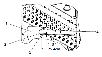
1)Insulation
2)ETS Tube Holder
3)ETS1 and ETS2
4)Wire Tie
- - - - -
7.22.11Installing a Compressor Discharge Temperature Sensor (CPDS)
The Compressor Discharge Temperature Sensor (CPDS), see Figure 7.25, monitors refrigerant temperature in the dome of the compressor.
Figure 7.25 Compressor Discharge Temperature Sensor (CPDS)
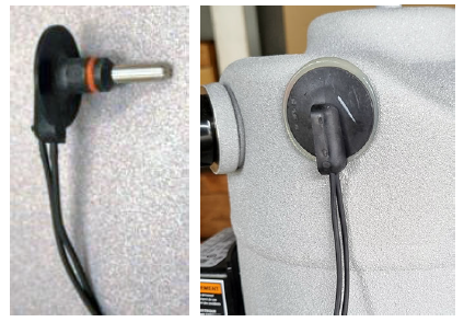
1.Ensure the unit is disconnected from the power source.
2.Verify that the Start-Stop switch (ST) is in the “0” position.
3.Remove the existing sensor.
4.Clean all silicone sealer and dielectric compound from the sensor well. Make sure that the well is clean and dry. The top of the compressor, where the sensor seals, must also be clean and dry.
5.Using the syringe supplied with the replacement sensor, squeeze all of the dielectric compound into the sensor well.
6.Place a bead of the silicone sealer supplied with the replacement sensor around the sensor sealing ring. Insert sensor into the well with the leads parallel to the suction fitting.
7.Reconnect the sensor and run a Pre-Trip P5. See Section 4.5 for Pre-Trip Descriptions.
7.22.12Sensor Resistance Values
Table 7–2 Sensor Resistance - AMBS, DTS, ETS, RRS, RTS, SRS, STS
|
°F |
OHMS |
°C |
°F |
OHMS |
||
|---|---|---|---|---|---|---|
|
-40 |
-40 |
336,500 |
6 |
42.8 |
24,173 |
|
|
-39 |
-38.2 |
314,773 |
7 |
44.6 |
23,017 |
|
|
-38 |
-36.4 |
294,600 |
8 |
46.4 |
21,922 |
|
|
-37 |
-34.6 |
275,836 |
9 |
48.2 |
20,886 |
|
|
-36 |
-32.8 |
258,336 |
10 |
50 |
19,900 |
|
|
-35 |
-31 |
242,850 |
11 |
51.8 |
18,975 |
|
|
-34 |
-29.2 |
228,382 |
12 |
53.6 |
18,093 |
|
|
-33 |
-27.4 |
214,164 |
13 |
55.4 |
17,258 |
|
|
-32 |
-25.6 |
200,909 |
14 |
57.2 |
16,466 |
|
|
-31 |
-23.8 |
188,545 |
15 |
59 |
15,715 |
|
|
-30 |
-22.0 |
177,000 |
16 |
60.8 |
15,002 |
|
|
-29 |
-20.2 |
166,360 |
17 |
62.6 |
14,325 |
|
|
-28 |
-18.4 |
156,426 |
18 |
64.4 |
13,683 |
|
|
-27 |
-16.6 |
147,148 |
19 |
66.2 |
13,073 |
|
|
-26 |
-14.8 |
138,478 |
20 |
68 |
12,494 |
|
|
-25 |
-13 |
130,374 |
21 |
69.8 |
11,944 |
|
|
-24 |
-11.2 |
122,794 |
22 |
71.6 |
11,420 |
|
|
-23 |
-9.4 |
115,702 |
23 |
73.4 |
10,923 |
|
|
-22 |
-7.6 |
109,063 |
24 |
75.2 |
10,450 |
|
|
-21 |
-5.8 |
102,846 |
25 |
77 |
10,000 |
|
|
-20 |
-4 |
97,022 |
26 |
78.8 |
9,572 |
|
|
-19 |
-2.2 |
91,563 |
27 |
80.6 |
9,164 |
|
|
-18 |
-0.4 |
86,445 |
28 |
82.4 |
8,777 |
|
|
-17 |
1.4 |
81,644 |
29 |
84.2 |
8,407 |
|
|
-16 |
3.2 |
77,139 |
30 |
86 |
8,055 |
|
|
-15 |
5 |
72,910 |
31 |
87.8 |
7,720 |
|
|
-14 |
6.8 |
68,938 |
32 |
89.6 |
7,401 |
|
|
-13 |
8.6 |
65,206 |
33 |
91.4 |
7,096 |
|
|
-12 |
10.4 |
61,699 |
34 |
93.2 |
6,806 |
|
|
-11 |
12.2 |
58,401 |
35 |
95 |
6,529 |
|
|
-10 |
14 |
55,330 |
36 |
96.8 |
6,265 |
|
|
-9 |
15.8 |
52,381 |
37 |
98.6 |
6,013 |
|
|
-8 |
17.6 |
49,634 |
38 |
100.4 |
5,772 |
|
|
-7 |
19.4 |
47,047 |
39 |
102.2 |
5,543 |
|
|
-6 |
21.2 |
44,610 |
40 |
104.0 |
5,323 |
|
|
-5 |
23 |
42,314 |
41 |
105.8 |
5,114 |
|
|
-4 |
24.8 |
40,149 |
42 |
107.6 |
4,914 |
|
|
-3 |
26.6 |
38,108 |
43 |
109.4 |
4,723 |
|
|
-2 |
28.4 |
36,182 |
44 |
111.2 |
4,540 |
|
|
-1 |
30.2 |
34,365 |
45 |
113 |
4,365 |
|
|
0 |
32 |
32,650 |
46 |
114.8 |
4,198 |
|
|
1 |
33.8 |
31,030 |
47 |
116.6 |
4,038 |
|
|
2 |
35.6 |
29,500 |
48 |
118.4 |
3,885 |
|
|
3 |
37.4 |
28,054 |
49 |
120.2 |
3,739 |
|
|
4 |
39.2 |
26,688 |
50 |
122 |
3,599 |
|
|
5 |
41 |
25,396 |
Table 7–3 Sensor Resistance - CPDS
|
°F |
OHMS |
°C |
°F |
OHMS |
||
|---|---|---|---|---|---|---|
|
-40 |
-40 |
2,889,600 |
18 |
64.4 |
117,656 |
|
|
-38 |
-36.4 |
2,532,872 |
20 |
68.0 |
107,439 |
|
|
-36 |
-32.8 |
2,225,078 |
22 |
71.6 |
98,194 |
|
|
-34 |
-29.2 |
1,957,446 |
24 |
75.2 |
89,916 |
|
|
-32 |
-25.6 |
1,724,386 |
25 |
77 |
86,113 |
|
|
-30 |
-22.0 |
1,522,200 |
26 |
78.8 |
82,310 |
|
|
-28 |
-18.4 |
1,345,074 |
28 |
82.4 |
75,473 |
|
|
-26 |
-14.8 |
1,190,945 |
30 |
83.0 |
69,281 |
|
|
-24 |
-11.2 |
1,056,140 |
32 |
89.6 |
63,648 |
|
|
-22 |
-7.6 |
938,045 |
34 |
93.2 |
58,531 |
|
|
-20 |
-4.0 |
834,716 |
36 |
96.8 |
53,887 |
|
|
-18 |
-0.4 |
743,581 |
38 |
100.4 |
49,656 |
|
|
-16 |
3.2 |
663,593 |
40 |
104.0 |
45,812 |
|
|
-14 |
6.8 |
593,030 |
42 |
107.6 |
42,294 |
|
|
-12 |
10.4 |
530,714 |
44 |
111.2 |
39,078 |
|
|
-10 |
14.0 |
475,743 |
46 |
114.8 |
36,145 |
|
|
-8 |
17.6 |
426,904 |
48 |
118.4 |
33,445 |
|
|
-6 |
21.2 |
383,706 |
50 |
122.0 |
30,985 |
|
|
-4 |
24.8 |
345,315 |
52 |
125.6 |
28,724 |
|
|
-2 |
28.4 |
311,165 |
54 |
129.2 |
26,651 |
|
|
0 |
32.0 |
280,824 |
56 |
132.8 |
27,750 |
|
|
2 |
35.6 |
253,682 |
58 |
136.4 |
23,005 |
|
|
4 |
39.2 |
229,499 |
60 |
140.0 |
21,396 |
|
|
6 |
42.8 |
207,870 |
62 |
143.6 |
19,909 |
|
|
8 |
46.4 |
188,494 |
64 |
147.2 |
18,550 |
|
|
10 |
50.0 |
171,165 |
66 |
150.8 |
17,294 |
|
|
12 |
53.6 |
155,574 |
68 |
154.4 |
16,133 |
|
|
14 |
57.2 |
141,590 |
70 |
158.0 |
15,067 |
|
|
16 |
60.8 |
129,000 |
72 |
161.6 |
14,078 |
The Humidity Sensor (HS) is an optional component that allows setting of a humidity set point in the controller. In dehumidification mode, the controller will operate to reduce internal container moisture level. When the sensor is disabled, it will be added as an event in the DataLINE report.
7.23.1Disabling the Humidity Sensor
If a humidity sensor fails and is not going to be replaced, the sensor operation can be disabled at the unit display. Once disabled, any related alarms will be masked and PTI tests will be skipped.
1.Press the CODE SELECT key.
2.Use the Arrow keys until Cd33 is displayed, then press the ENTER key.
3.Use the Arrow keys to select “diSbl” and press ENTER. This sets the humidity sensor configuration variable to OFF.
4.It is recommended to unplug the humidity sensor from the unit (capping off the sensor plug). This is essential as the humidity sensor shares the power source with other components.
7.23.2Checking the Operation of the Humidity Sensor
This procedure is to be performed in an effort to ease the troubleshooting of the humidity sensor. When performing this procedure and while working on the unit, always follow the proper lockout / tagout procedures. See Figure 7.26 for reference.
Figure 7.26 Humidity Sensor (HS)
1)Cap opening (6 cm)
2)Cap hole (3 cm)
3)Humidity Sensor (HS)
4)Salt water solution
- - - - -
Items Required:
•One 7/16” socket wrench or nut driver.
•One 1/4” socket wrench or nut driver.
•One clean, clear water bottle with a minimum 6 cm (2.5 in) opening and capacity to hold 500 ml (16.9 oz).
•100 ml (3.4 oz) of fresh water - distilled if available.
•50 gm of Salt (NaCl).
Procedure:
1.Remove the left Upper Fresh Air Makeup Vent panel.
2.Remove the humidity sensor from the mounting hardware and bring to the front of the access panel.
3.Disconnect the humidity sensor from the harness.
4.Drill a 3 cm (1.25 in) hole in the cap of a bottle.
5.Pour approximately 100 ml (3.4 oz) of water into the empty clean bottle.
6.Add salt to the water until it is present at the bottom of the bottle.
7.Cap the bottle and tape over the drilled hole.
8.Shake the bottle until the salt dissolves and water is saturated.
NOTE: To ensure saturation, add additional salt until it settles at the bottom without dissolving while shaking.
9.Remove the cap and insert the humidity sensor into the bottle through the bottle opening and pull the connector back through the drilled hole in the cap. Then, secure the cap and seal the wire going through the cap.
NOTE: Make sure that the sensor is not at all in contact with the salt water.
10.Allow the saturated salt mixture to settle for approximately ten minutes.
11.Reconnect the humidity sensor to the harness and power the reefer unit on.
12.Press the CODE SELECT key on the keypad.
13.Use the Arrow keys until “Cd17” is displayed then press the ENTER key.
14.This displays the humidity sensor reading. Verify the reading is between 60% and 85% relative humidity.
15.If the humidity sensor display is outside of this range, reconfirm the salt mixture and retest. If not in range, replace the sensor at the next opportunity.
16.Wipe clean and reinstall the humidity sensor and access panel. Torque the access panel hardware to 69 kg-cm (60 in.-lbs.) using a crossing pattern similar to the numbering below.
If the panel gasket is damaged, replace it.
7.24Vent Position Sensor (VPS)
The optional vent position sensor (VPS) determines fresh air vent position in near real-time via function code Cd45.
The fresh air vent position sensor alarm (AL250) will occur if the sensor reading is not stable for four minutes or if the sensor is outside of its valid range (shorted or open). This can occur if the vent is loose or the panel is defective. To confirm a defective panel, assure that the wing nut is secure and then power cycle the unit. If the alarm immediately reappears as active, the panel should be replaced. The alarm should immediately go inactive. Check the four minute stability requirement. If the alarm reoccurs after the four minutes and the panel was known to have been stable, then the sensor should be replaced.
In order to replace the Upper VPS, the panel must be removed and replaced with another upper fresh air panel equipped with VPS. Upon installation, a new VPS assembly requires calibration.
7.24.1Vent Position Sensor (VPS) Calibration
1.Rotate the vent to the 0 CMH / CFM position. Cd45 will automatically appear on the unit display.
2.Press and hold the ENTER key for five seconds.
3.After the ENTER key has been pressed the display will read “CAL” (for calibration).
4.Press and hold the ALT MODE key for five seconds.
5.After the calibration has been completed, Cd45 will display 0 CMH / CFM.
The optional cargo sensor outputs a resistance that is read by the controller as a temperature. The sensor will update the cargo status every 6 hours and display the last reading, whenever the controller is powered on.
7.25.1Cargo Sensor Operational Values
When diagnosing the cargo sensor, the box temperatures should be above 3°C (37.4°F). Temperatures lower than this can cause frost to build up on the lens of the cargo sensor, giving a false reading.
To check the last reading of the cargo sensor, follow the instructions below.
1.Press the ALT MODE key on the keypad.
2.Use the Arrow keys until “dC” is displayed, then press the ENTER key.
3.Use the Arrow keys until “dC14” is displayed, then press ENTER to display the readout.
4.The temperature displayed should fall within one of the temperature ranges listed in the table below. Check the table to see the recommended action to take. If battery replacement is necessary, ensure proper connections and a fresh set of batteries (kit number 76-00931-00) are installed.
|
Signal Range |
Condition |
Recommended Action |
|---|---|---|
|
21 to 16°C |
Cargo Sensor Fault |
1. Verify wiring to interrogator port #4 inside container. 2. Check IR sensor window on cargo sensor for obstruction. 3. Replace cargo sensor. |
|
14 to 9°C |
Cargo present, battery low |
No immediate action, replace battery before next trip |
|
7° to 2°C |
Cargo present |
No action required |
|
1° to -4°C |
Cargo not present, battery low |
No immediate action, replace battery before next trip |
|
-6° to -11°C |
Cargo not present |
No action required |
|
-14° to -49°C |
Open circuit / dead battery |
Replace battery with service kit 76-00931-00 |
|
-50°C |
Interrogator installed incorrectly |
Remove plug and reinstall with proper orientation. |
|
33°C |
Interrogator installed incorrectly |
Remove plug and reinstall with proper orientation. |
Refer to the T-374 EverFRESH Manual for detailed procedures and technical information related to the EverFRESH controlled atmosphere system. The manual is located in the Literature section of the Container Refrigeration website. To find the manual from the Literature section, click on Options > EverFRESH.
7.27Maintenance of Painted Surfaces
The refrigeration unit is protected by a special paint system against the corrosive atmosphere in which it normally operates. However, should the paint system be damaged, the base metal can corrode. In order to protect the refrigeration unit from the highly corrosive sea atmosphere, or if the protective paint system is scratched or damaged, clean the area to bare metal using a wire brush, emery paper or equivalent cleaning method. Immediately following cleaning, apply paint to the area, and allow to dry. Refer to the Parts List for proper paint selection.
Table 7–4 R-134a Refrigerant Pressure Temperature Chart
Note: Underline figures are inches of mercury vacuum
|
°F |
°C |
PSIG |
°C |
°F |
BAR |
|
|---|---|---|---|---|---|---|
|
-40 |
-40.0 |
14.8 |
-40 |
-40.0 |
-0.49 |
|
|
-38 |
-38.9 |
13.9 |
-39 |
-38.2 |
-0.46 |
|
|
-36 |
-37.8 |
13.0 |
-38 |
-36.4 |
-0.43 |
|
|
-34 |
-36.7 |
12.0 |
-37 |
-34.6 |
-0.40 |
|
|
-32 |
-35.6 |
10.9 |
-36 |
-32.8 |
-0.37 |
|
|
-30 |
-34.4 |
9.8 |
-35 |
-31.0 |
-0.34 |
|
|
-28 |
-33.3 |
8.7 |
-34 |
-29.2 |
-0.30 |
|
|
-26 |
-32.2 |
7.5 |
-33 |
-27.4 |
-0.27 |
|
|
-24 |
-31.1 |
6.3 |
-32 |
-25.6 |
-0.23 |
|
|
-22 |
-30.0 |
5.0 |
-31 |
-23.8 |
-0.20 |
|
|
-20 |
-28.9 |
3.7 |
-30 |
-22.0 |
-0.16 |
|
|
-18 |
-27.8 |
2.3 |
-29 |
-20.2 |
-0.12 |
|
|
-16 |
-26.7 |
0.8 |
-28 |
-18.4 |
-0.07 |
|
|
-14 |
-25.6 |
0.3 |
-27 |
-16.6 |
-0.03 |
|
|
-12 |
-24.4 |
1.1 |
-26 |
-14.8 |
0.02 |
|
|
-10 |
-23.3 |
1.9 |
-25 |
-13.0 |
0.06 |
|
|
-8 |
-22.2 |
2.8 |
-24 |
-11.2 |
0.11 |
|
|
-6 |
-21.1 |
3.6 |
-23 |
-9.4 |
0.16 |
|
|
-4 |
-20.0 |
4.6 |
-22 |
-7.6 |
0.22 |
|
|
-2 |
-18.9 |
5.5 |
-21 |
-5.8 |
0.27 |
|
|
0 |
-17.8 |
6.5 |
-20 |
-4.0 |
0.33 |
|
|
2 |
-16.7 |
7.5 |
-19 |
-2.2 |
0.39 |
|
|
4 |
-15.6 |
8.5 |
-18 |
-0.4 |
0.45 |
|
|
6 |
-14.4 |
9.6 |
-17 |
1.4 |
0.51 |
|
|
8 |
-13.3 |
10.8 |
-16 |
3.2 |
0.57 |
|
|
10 |
-12.2 |
11.9 |
-15 |
5.0 |
0.64 |
|
|
12 |
-11.1 |
13.1 |
-14 |
6.8 |
0.71 |
|
|
14 |
-10.0 |
14.4 |
-13 |
8.6 |
0.78 |
|
|
16 |
-8.9 |
15.7 |
-12 |
10.4 |
0.85 |
|
|
18 |
-7.8 |
17.0 |
-11 |
12.2 |
0.93 |
|
|
20 |
-6.7 |
18.4 |
-10 |
14.0 |
1.01 |
|
|
22 |
-5.6 |
19.9 |
-9 |
15.8 |
1.09 |
|
|
24 |
-4.4 |
21.3 |
-8 |
17.6 |
1.17 |
|
|
26 |
-3.3 |
22.9 |
-7 |
19.4 |
1.25 |
|
|
28 |
-2.2 |
24.5 |
-6 |
21.2 |
1.34 |
|
|
30 |
-1.1 |
26.1 |
-5 |
23.0 |
1.43 |
|
|
32 |
0.0 |
27.8 |
-4 |
24.8 |
1.53 |
|
|
34 |
1.1 |
29.5 |
-3 |
26.6 |
1.62 |
|
|
36 |
2.2 |
31.3 |
-2 |
28.4 |
1.72 |
|
|
38 |
3.3 |
33.1 |
-1 |
30.2 |
1.82 |
|
|
40 |
4.4 |
35.0 |
0 |
32.0 |
1.93 |
|
|
42 |
5.6 |
37.0 |
1 |
33.8 |
2.04 |
|
|
44 |
6.7 |
39.0 |
2 |
35.6 |
2.15 |
|
|
46 |
7.8 |
41.1 |
3 |
37.4 |
2.26 |
|
|
48 |
8.9 |
43.2 |
4 |
39.2 |
2.38 |
|
|
50 |
10.0 |
45.4 |
5 |
41.0 |
2.50 |
|
|
52 |
11.1 |
47.7 |
6 |
42.8 |
2.62 |
|
|
54 |
12.2 |
50.0 |
7 |
44.6 |
2.75 |
|
|
56 |
13.3 |
52.4 |
8 |
46.4 |
2.88 |
|
|
58 |
14.4 |
54.9 |
9 |
48.2 |
3.01 |
|
|
60 |
15.6 |
57.4 |
10 |
50.0 |
3.15 |
|
|
62 |
16.7 |
60.0 |
11 |
51.8 |
3.29 |
|
|
64 |
17.8 |
62.7 |
12 |
53.6 |
3.43 |
|
|
66 |
18.9 |
65.4 |
13 |
55.4 |
3.58 |
|
|
68 |
20.0 |
68.2 |
14 |
57.2 |
3.73 |
|
|
70 |
21.1 |
71.1 |
15 |
59.0 |
3.88 |
|
|
72 |
22.2 |
74.1 |
16 |
60.8 |
4.04 |
|
|
74 |
23.3 |
77.1 |
17 |
62.6 |
4.21 |
|
|
76 |
24.4 |
80.2 |
18 |
64.4 |
4.37 |
|
|
78 |
25.6 |
83.4 |
19 |
66.2 |
4.54 |
|
|
80 |
26.7 |
86.7 |
20 |
68.0 |
4.72 |
|
|
82 |
27.8 |
90.0 |
21 |
69.8 |
4.90 |
|
|
84 |
28.9 |
93.5 |
22 |
71.6 |
5.08 |
|
|
86 |
30.0 |
97.0 |
23 |
73.4 |
5.27 |
|
|
88 |
31.1 |
100.6 |
24 |
75.2 |
5.46 |
|
|
90 |
32.2 |
104.3 |
25 |
77.0 |
5.65 |
|
|
92 |
33.3 |
108.1 |
26 |
78.8 |
5.85 |
|
|
94 |
34.4 |
112.0 |
27 |
80.6 |
6.06 |
|
|
96 |
35.6 |
115.9 |
28 |
82.4 |
6.27 |
|
|
98 |
36.7 |
120.0 |
29 |
84.2 |
6.48 |
|
|
100 |
37.8 |
124.2 |
30 |
86.0 |
6.70 |
|
|
102 |
38.9 |
128.4 |
31 |
87.8 |
6.93 |
|
|
104 |
40.0 |
132.7 |
32 |
89.6 |
7.15 |
|
|
106 |
41.1 |
137.2 |
33 |
91.4 |
7.39 |
|
|
108 |
42.2 |
141.7 |
34 |
93.2 |
7.63 |
|
|
110 |
43.3 |
146.4 |
35 |
95.0 |
7.87 |
|
|
112 |
44.4 |
151.1 |
36 |
96.8 |
8.12 |
|
|
114 |
45.6 |
156.0 |
37 |
98.6 |
8.37 |
|
|
116 |
46.7 |
160.9 |
38 |
100.4 |
8.63 |
|
|
118 |
47.8 |
166.0 |
39 |
102.2 |
8.90 |
|
|
120 |
48.9 |
171.2 |
40 |
104.0 |
9.17 |
|
|
122 |
50.0 |
176.5 |
41 |
105.8 |
9.44 |
|
|
124 |
51.1 |
181.8 |
42 |
107.6 |
9.72 |
|
|
126 |
52.2 |
187.4 |
43 |
109.4 |
10.01 |
|
|
128 |
53.3 |
193.0 |
44 |
111.2 |
10.30 |
|
|
130 |
54.4 |
198.7 |
45 |
113.0 |
10.60 |
|
|
132 |
55.6 |
204.6 |
46 |
114.8 |
10.90 |
|
|
134 |
56.7 |
210.6 |
47 |
116.6 |
11.21 |
|
|
136 |
57.8 |
216.7 |
48 |
118.4 |
11.53 |
|
|
138 |
58.9 |
222.9 |
49 |
120.2 |
11.85 |
|
|
140 |
60.0 |
229.2 |
50 |
122.0 |
12.18 |
|
|
142 |
61.1 |
235.7 |
51 |
123.8 |
12.51 |
|
|
144 |
62.2 |
242.3 |
52 |
125.6 |
12.85 |
|
|
146 |
63.3 |
249.0 |
53 |
127.4 |
13.20 |
|
|
148 |
64.4 |
255.9 |
54 |
129.2 |
13.56 |
|
|
150 |
65.6 |
262.9 |
55 |
131.0 |
13.92 |
|
|
56 |
132.8 |
14.28 |
||||
|
57 |
134.6 |
14.66 |
||||
|
58 |
136.4 |
15.04 |
||||
|
59 |
138.2 |
15.42 |
||||
|
60 |
140.0 |
15.82 |
||||
|
61 |
141.8 |
16.22 |
||||
|
62 |
143.6 |
16.63 |
||||
|
63 |
145.4 |
17.04 |
||||
|
64 |
147.2 |
17.47 |
||||
|
65 |
149.0 |
17.90 |
Table 7–5 R-513A Refrigerant Pressure Temperature Chart
Note: Underline figures are inches of mercury vacuum
|
°F |
°C |
PSIG |
°C |
°F |
BAR |
|
|---|---|---|---|---|---|---|
|
-40 |
-40.0 |
9.8 |
-40 |
-40.0 |
-0.32 |
|
|
-38 |
-38.9 |
8.6 |
-39 |
-38.2 |
-0.28 |
|
|
-36 |
-37.8 |
7.4 |
-38 |
-36.4 |
-0.25 |
|
|
-34 |
-36.7 |
6.2 |
-37 |
-34.6 |
-0.21 |
|
|
-32 |
-35.6 |
4.9 |
-36 |
-32.8 |
-0.17 |
|
|
-30 |
-34.4 |
3.6 |
-35 |
-31.0 |
-0.13 |
|
|
-28 |
-33.3 |
2.2 |
-34 |
-29.2 |
-0.09 |
|
|
-26 |
-32.2 |
0.7 |
-33 |
-27.4 |
-0.05 |
|
|
-24 |
-31.1 |
0.4 |
-32 |
-25.6 |
0.00 |
|
|
-22 |
-30.0 |
1.1 |
-31 |
-23.8 |
0.04 |
|
|
-20 |
-28.9 |
1.9 |
-30 |
-22.0 |
0.09 |
|
|
-18 |
-27.8 |
2.8 |
-29 |
-20.2 |
0.14 |
|
|
-16 |
-26.7 |
3.7 |
-28 |
-18.4 |
0.19 |
|
|
-14 |
-25.6 |
4.6 |
-27 |
-16.6 |
0.25 |
|
|
-12 |
-24.4 |
5.5 |
-26 |
-14.8 |
0.30 |
|
|
-10 |
-23.3 |
6.5 |
-25 |
-13.0 |
0.36 |
|
|
-8 |
-22.2 |
7.5 |
-24 |
-11.2 |
0.42 |
|
|
-6 |
-21.1 |
8.5 |
-23 |
-9.4 |
0.48 |
|
|
-4 |
-20.0 |
9.6 |
-22 |
-7.6 |
0.54 |
|
|
-2 |
-18.9 |
10.7 |
-21 |
-5.8 |
0.61 |
|
|
0 |
-17.8 |
11.9 |
-20 |
-4.0 |
0.67 |
|
|
2 |
-16.7 |
13.1 |
-19 |
-2.2 |
0.74 |
|
|
4 |
-15.6 |
14.3 |
-18 |
-0.4 |
0.81 |
|
|
6 |
-14.4 |
15.6 |
-17 |
1.4 |
0.89 |
|
|
8 |
-13.3 |
16.9 |
-16 |
3.2 |
0.96 |
|
|
10 |
-12.2 |
18.3 |
-15 |
5.0 |
1.04 |
|
|
12 |
-11.1 |
19.7 |
-14 |
6.8 |
1.12 |
|
|
14 |
-10.0 |
21.1 |
-13 |
8.6 |
1.21 |
|
|
16 |
-8.9 |
22.6 |
-12 |
10.4 |
1.29 |
|
|
18 |
-7.8 |
24.2 |
-11 |
12.2 |
1.38 |
|
|
20 |
-6.7 |
25.8 |
-10 |
14.0 |
1.47 |
|
|
22 |
-5.6 |
27.5 |
-9 |
15.8 |
1.56 |
|
|
24 |
-4.4 |
29.2 |
-8 |
17.6 |
1.66 |
|
|
26 |
-3.3 |
30.9 |
-7 |
19.4 |
1.76 |
|
|
28 |
-2.2 |
32.7 |
-6 |
21.2 |
1.86 |
|
|
30 |
-1.1 |
34.6 |
-5 |
23.0 |
1.97 |
|
|
32 |
0.0 |
36.5 |
-4 |
24.8 |
2.07 |
|
|
34 |
1.1 |
38.5 |
-3 |
26.6 |
2.18 |
|
|
36 |
2.2 |
40.5 |
-2 |
28.4 |
2.30 |
|
|
38 |
3.3 |
42.6 |
-1 |
30.2 |
2.41 |
|
|
40 |
4.4 |
44.8 |
0 |
32.0 |
2.53 |
|
|
42 |
5.6 |
47.0 |
1 |
33.8 |
2.65 |
|
|
44 |
6.7 |
49.3 |
2 |
35.6 |
2.78 |
|
|
46 |
7.8 |
51.6 |
3 |
37.4 |
2.91 |
|
|
48 |
8.9 |
54.0 |
4 |
39.2 |
3.04 |
|
|
50 |
10.0 |
56.5 |
5 |
41.0 |
3.18 |
|
|
52 |
11.1 |
59.0 |
6 |
42.8 |
3.32 |
|
|
54 |
12.2 |
61.6 |
7 |
44.6 |
3.46 |
|
|
56 |
13.3 |
64.3 |
8 |
46.4 |
3.60 |
|
|
58 |
14.4 |
67.0 |
9 |
48.2 |
3.75 |
|
|
60 |
15.6 |
69.8 |
10 |
50.0 |
3.91 |
|
|
62 |
16.7 |
72.7 |
11 |
51.8 |
4.06 |
|
|
64 |
17.8 |
75.7 |
12 |
53.6 |
4.22 |
|
|
66 |
18.9 |
78.7 |
13 |
55.4 |
4.39 |
|
|
68 |
20.0 |
81.8 |
14 |
57.2 |
4.56 |
|
|
70 |
21.1 |
85.0 |
15 |
59.0 |
4.73 |
|
|
72 |
22.2 |
88.2 |
16 |
60.8 |
4.91 |
|
|
74 |
23.3 |
91.6 |
17 |
62.6 |
5.09 |
|
|
76 |
24.4 |
95.0 |
18 |
64.4 |
5.27 |
|
|
78 |
25.6 |
98.5 |
19 |
66.2 |
5.46 |
|
|
80 |
26.7 |
102.1 |
20 |
68.0 |
5.65 |
|
|
82 |
27.8 |
105.7 |
21 |
69.8 |
5.85 |
|
|
84 |
28.9 |
109.5 |
22 |
71.6 |
6.05 |
|
|
86 |
30.0 |
113.3 |
23 |
73.4 |
6.26 |
|
|
88 |
31.1 |
117.3 |
24 |
75.2 |
6.47 |
|
|
90 |
32.2 |
121.3 |
25 |
77.0 |
6.68 |
|
|
92 |
33.3 |
125.4 |
26 |
78.8 |
6.90 |
|
|
94 |
34.4 |
129.6 |
27 |
80.6 |
7.13 |
|
|
96 |
35.6 |
133.9 |
28 |
82.4 |
7.36 |
|
|
98 |
36.7 |
138.3 |
29 |
84.2 |
7.59 |
|
|
100 |
37.8 |
142.8 |
30 |
86.0 |
7.83 |
|
|
102 |
38.9 |
147.4 |
31 |
87.8 |
8.07 |
|
|
104 |
40.0 |
152.0 |
32 |
89.6 |
8.32 |
|
|
106 |
41.1 |
156.8 |
33 |
91.4 |
8.57 |
|
|
108 |
42.2 |
161.7 |
34 |
93.2 |
8.83 |
|
|
110 |
43.3 |
166.7 |
35 |
95.0 |
9.10 |
|
|
112 |
44.4 |
171.8 |
36 |
96.8 |
9.37 |
|
|
114 |
45.6 |
177.0 |
37 |
98.6 |
9.64 |
|
|
116 |
46.7 |
182.3 |
38 |
100.4 |
9.92 |
|
|
118 |
47.8 |
187.7 |
39 |
102.2 |
10.21 |
|
|
120 |
48.9 |
193.3 |
40 |
104.0 |
10.50 |
|
|
122 |
50.0 |
198.9 |
41 |
105.8 |
10.79 |
|
|
124 |
51.1 |
204.7 |
42 |
107.6 |
11.10 |
|
|
126 |
52.2 |
210.5 |
43 |
109.4 |
11.40 |
|
|
128 |
53.3 |
216.5 |
44 |
111.2 |
11.72 |
|
|
130 |
54.4 |
222.7 |
45 |
113.0 |
12.04 |
|
|
132 |
55.6 |
228.9 |
46 |
114.8 |
12.36 |
|
|
134 |
56.7 |
235.2 |
47 |
116.6 |
12.70 |
|
|
136 |
57.8 |
241.7 |
48 |
118.4 |
13.03 |
|
|
138 |
58.9 |
248.3 |
49 |
120.2 |
13.38 |
|
|
140 |
60.0 |
255.1 |
50 |
122.0 |
13.73 |
|
|
142 |
61.1 |
261.9 |
51 |
123.8 |
14.09 |
|
|
144 |
62.2 |
268.9 |
52 |
125.6 |
14.45 |
|
|
146 |
63.3 |
276.1 |
53 |
127.4 |
14.82 |
|
|
148 |
64.4 |
283.3 |
54 |
129.2 |
15.20 |
|
|
150 |
65.6 |
290.8 |
55 |
131.0 |
15.58 |
|
|
56 |
132.8 |
15.97 |
||||
|
57 |
134.6 |
16.37 |
||||
|
58 |
136.4 |
16.77 |
||||
|
59 |
138.2 |
17.18 |
||||
|
60 |
140.0 |
17.60 |
||||
|
61 |
141.8 |
18.03 |
||||
|
62 |
143.6 |
18.46 |
||||
|
63 |
145.4 |
18.90 |
||||
|
64 |
147.2 |
19.35 |
||||
|
65 |
149.0 |
19.80 |