Operation
Beware of unannounced starting of the evaporator and condenser fans. The unit may cycle the fans and compress or unexpectedly as control requirements dictate.
1.Check inside the unit for the following conditions:
•Check channels or “T” bar floor for cleanliness. Channels must be free of debris for proper air circulation.
•Check container panels, insulation and door seals for damage. Perform permanent or temporary repairs.
•Check visually that the evaporator fan motor mounting bolts are properly secured. Refer to Section 7.10.
•Check for visible corrosion on the evaporator stator and fan deck. See Section 7.11.
•Check for dirt or grease on evaporator fans or fan deck and clean if necessary. See Section 7.11.
•Check evaporator coil for cleanliness or obstructions. Wash with fresh water. See Section 7.11.
•Check defrost drain pans and drain lines for obstructions and clear if necessary. Wash with fresh water.
•Check panels on refrigeration unit for loose bolts and condition of panels. Make sure T.I.R. devices are in place on access panels.
2.Check condenser coil for cleanliness. Wash with fresh water. See Section 7.4.
3.Open the control box door. Check for loose electrical connections or hardware.
4.Check color of moisture-liquid indicator.
Do not attempt to remove power plug(s) before turning OFF the Start-Stop switch (ST), unit circuit breaker(s) and external power source.
Make sure the power plugs are clean and dry before connecting to power receptacle.
5.2.1Connecting to 380/460 VAC Power
1.Make sure the unit Start-Stop switch (ST) is Off (“0”). See Figure 3.6.
2.Make sure circuit breaker CB1 in the control box is Off (“0”). See Figure 3.6.
3.Plug the 460 VAC (yellow) cable into a de-energized 380/460 VAC, 3-phase power source and energize the power source.
4.Place circuit breaker CB1 On (“I”).
5.Close and secure the control box door.
5.2.2Connecting to 190/230 VAC Power
To allow unit operation on nominal 230 volt power an autotransformer, as shown in Figure 5.1, is required. The autotransformer is fitted with a 230 VAC cable and a receptacle to accept the standard 460 VAC power plug. The 230 volt cable is black in color while the 460 volt cable is yellow. The transformer may also be equipped with a circuit breaker (CB2). The transformer is a step-up transformer that provides 380/460 VAC, 3-phase, 50/60 Hz power to the unit when the 230 VAC power cable is connected to a 190/230 VAC, 3-phase power source.
Procedure:
1.Make sure the unit Start-Stop switch (ST) is Off (“0”). See Figure 3.6.
2.Make sure circuit breaker CB1 in the control box is Off (“0”). See Figure 3.6.
3.Make sure circuit breaker CB2 on the transformer is Off (“0”). See Figure 5.1.
4.Plug in and lock the 460 VAC power plug at the receptacle on the transformer.
5.Plug the 230 VAC (black) cable into a de-energized 190/230 VAC, 3-phase power source and energize the power source.
6.Set both circuit breakers CB1 and CB2 to On (“I”).
7.Close and secure the control box door.
Figure 5.1 Autotransformer

1)Circuit Breaker (CB2) 230-Volt
2)460 VAC Power Receptacle
3)Dual Voltage Modular Autotransformer
- - - - -
5.3Adjusting the Fresh Air Makeup Vent
The purpose of the fresh air makeup vent, see Section 3.3.10, is to provide ventilation for commodities that require fresh air circulation. The vent must be closed when transporting frozen foods. Air exchange depends on static pressure differential, which will vary depending on the container and how the container is loaded.
Units may be equipped with a vent position sensor (VPS) to determine the position of the upper fresh air vent (as equipped) and sends data to the controller display.
5.3.1Upper Fresh Air Makeup Vent
Two slots and a stop are designed into the upper fresh air disc for air flow adjustments. The first slot allows for a 0 to 30% air flow; the second slot allows for a 30 to 100% air flow.
To adjust the percentage of air flow, loosen the wing nut and rotate the disc until the desired percentage of air flow matches with the arrow. Tighten the wing nut.
To clear the gap between the slots, loosen the wing nut until the disc clears the stop.
See Figure 5.2 for air exchange values for an empty container. Higher values can be expected for a fully loaded container.
Figure 5.2 Upper Fresh Air Make Up Flow Chart

The vent position sensor (VPS) allows the user to view the fresh air vent position from the unit display at function code Cd45. This code is accessible via the CODE SELECT key.
The VPS position will display for 30 seconds whenever motion corresponding to 5 CMH (3 CFM) or greater is detected. It will scroll in intervals of 5 CMH (3 CFM).
The position of the vent will be recorded in the DataCORDER whenever the unit is running under AC power and during any of the following conditions:
•Trip Start
•Every power cycle
•Midnight
•Manual changes greater than 5 CMH (3 CFM) remaining in the new position for at least four minutes
NOTE: The user has four minutes to make necessary adjustments to the vent setting. This time calculation begins on the initial movement of the sensor. The vent can be moved to any position within the four minutes. On completion of the first four minutes, the vent is required to remain stable for the next four minutes. If vent position changes are detected during the four-minute stability period, AL250 will be generated. This provides the user with the ability to change the vent setting without generating multiple events in the DataCORDER.
5.4Connecting Water-Cooled Condenser
The water-cooled condenser (WCC), see Section 3.3.3, is an optional component chosen when cooling water is available and heating the surrounding air is objectionable, such as in a ship’s hold. If water-cooled operation is desired, connect in accordance with the following procedure.
1.Connect the water supply line to the inlet side of the condenser and the discharge line to the outlet side of the condenser. See Figure 3.10.
2.Maintain a flow rate of 11 to 26 liters per minute (3 to 7 gallons per minute). The Water Pressure Switch (WPS) will open to de-energize the condenser fan relay. The condenser fan motor will stop and remain stopped until the WPS closes.
3.To shift to air-cooled condenser operation, disconnect the water supply and the discharge line to the water-cooled condenser. The refrigeration unit will shift to air-cooled condenser operation when the WPS closes.
5.5Starting and Stopping Instructions
Make sure that the unit circuit breaker(s) CB1 & CB2 and the Start-Stop switch (ST) are in the “O” (OFF) position before connecting to any electrical power source.
NOTE: The electronic phase detection system will check for proper compressor rotation within the first 30 seconds. If rotation is not correct, the compressor will be stopped and restarted in the opposite direction. If the compressor is producing unusually loud and continuous noise after the first 30 seconds of operation, stop the unit and investigate.
1.Verify that power is properly applied, the fresh air vent is in position, and (if required) the water-cooled condenser is connected.
2.Turn the Start-Stop (ST) switch ON (“I”). See Figure 3.6.
As the controller is starting up, the display will show in sequence function codes: Cd40 (Container ID), Cd18 (Software Version) and Cd20 (Unit Model Number).
3.Continue with the Start Up Inspection. See Section 5.6.
1.Turn the Start-Stop (ST) switch OFF (“0”). See Figure 3.6.
1.Check rotation of the condenser fan and evaporator fans.
2.Check, and if required, set controller Function Codes Cd27 through Cd39 in accordance with desired operating parameters. See Section 4.2.2 for more details.
•Cd27: Defrost Interval
•Cd28: Temperature Units (C or F)
•Cd29: Failure Action (Mode)
•Cd30: In-Range Tolerance
•Cd31: Stagger Start Offset Time
•Cd32: System Current Limit
•Cd33: Humidity Setpoint
•Cd34: Economy Mode
•Cd35: Bulb Mode
•Cd36: Evaporator Fan Speed
•Cd37: Variable DTT Setting (Bulb Mode)
3.Check and, if required, set the DataCORDER Sensor Configuration at variable dCF02 in accordance with desired recording parameter. See Table 4–7 for sensor configurations.
4.Enter a Trip Start with the following instructions:
a.Press the ALT MODE key.
b.Use the Arrow keys to display “dC”, then press the ENTER key.
c.Use the Arrow keys to display “dC30”, then press and hold the ENTER key for 5 seconds.
d.The “Trip Start” event will be entered in the DataCORDER.
Pre-Trip Inspection is an independent controller function that suspends the normal refrigeration control mode activities and provides pre-programmed test routines of unit operations. See Section 4.5 for an explanation of Pre-Trip Inspection, the different modes of operation and a description of all Pre-Trip test codes.
5.7.1Starting a Pre-Trip from the Keypad
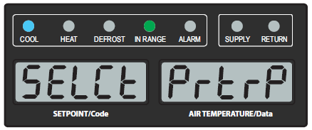
1.Press the PRE-TRIP key to access the Pre-Trip test selection menu.
2.The display will show “SELCt PrtrP” for up to five seconds. Press the ENTER key to bring up the Pre-Trip Inspection Test Selection menu.
If the unit is configured for TripWise and TripWise is On (code Cd65), the display shows “tripW OFF/EX/PASS/CHECK” for one second and then “SELCt PrtrP” for one second. The messages will alternate back and forth for a total of five seconds. Press the ENTER key while “SELCt PrtrP” is displayed to bring up the Pre-Trip Inspection Test Selection menu.
3.To Run an Automatic Test: Scroll through the selections by pressing the Arrow keys to display AUtO, AUtO1, AUtO2 or AUtO3 as desired, then press the ENTER key.
•The unit will execute the series of tests without any need for direct user interface. These tests vary in length, depending on the component under test.
•While tests are running, “P#-#” will appear on the left display; the #’s indicate the test number and sub-test. The right display will show a countdown time in minutes and seconds, indicating the amount of time remaining in the test.
NOTE: When a Pre-Trip Auto 1 test runs to completion without a failure, the unit will exit Pre-Trip mode and return to normal control operation. However, dehumidification and bulb mode must be reactivated manually if required.
NOTE: When a Pre-Trip Auto 2 test runs to completion without being interrupted, the unit will terminate Pre-Trip and display “Auto 2” “end.” The unit will suspend operation until the user presses the ENTER key.
4.When an automatic test fails, it will be repeated once. A repeated test failure will cause “FAIL” to be shown on the right display, with the corresponding test number to the left. The user may then press the Down Arrow key to repeat the test, the Up Arrow key to skip to the next test, or the PRE-TRIP key to terminate testing. The unit will wait indefinitely or until the user manually enters a command.
When a failure occurs during automatic testing, the unit will suspend operation awaiting operator intervention.
5.To Run an Individual Test: Scroll through the selections by pressing the Up or Down Arrow keys to display an individual test code. Press the ENTER key when the desired test code is displayed.
Individually selected tests, other than the LED / Display test, will perform the operations necessary to verify the operation of the component. At the conclusion, “PASS” or “FAIL” will be displayed. This message will remain displayed for up to three minutes, during which time a user may select another test. If the three minute time period expires, the unit will terminate Pre-Trip and return to control mode operation.
While the tests are being executed, the user may terminate the Pre-Trip diagnostics by pressing and holding the PRE-TRIP key. The unit will then resume normal operation. If the user decides to terminate a test but remain at the test selection menu, the user may press the Up Arrow key. When this is done, all test outputs will be de-energized and the test selection menu will be displayed.
Throughout the duration of any Pre-Trip test (except P-7 High Pressure Switch tests), the current limiting and pressure limiting processes are both active. The current limiting process is only active for P-7.
5.7.2Displaying Pre-Trip Test Results from the Keypad
1.Press the PRE-TRIP key to access the Pre-Trip test selection menu. “SELCt PrtrP” will be displayed.
2.Use the Arrow keys until “P rSLts” (Pre-Trip results) is displayed, then press the ENTER key.
3.The results for all Pre-Trip sub tests are available from this menu (i.e., 1-0, 1-1, etc).
The results will be displayed as “PASS” or “FAIL” for all the tests run to completion since power up. If a test has not been run since power up, dashes “-----” will be displayed.
A complete temperature probe check is performed during the P5 Pre-Trip test. A probe check is also run at the end of a defrost cycle; the defrost light will remain on during this period. If supply probes are within limits and return probes are within limits, the unit will return to normal operation. During normal operation, the controller continuously monitors and compares adjacent temperature probe readings.
The probe check procedure consists of running the evaporator fans for up to eight minutes in order to compare the readings from the adjacent temperature probes. If a significant difference in temperature readings is detected between probes, a defrost cycle, followed by another probe check may be initiated. Any continued disagreement between probes will prompt the controller to invalidate the failed temperature probe, and the backup probe will be used for temperature control.
In Perishable Mode, both pairs of supply and return probes are monitored for probe disagreement. Probe disagreement is considered a difference of 0.5°C (0.9°F) or greater between the supply air sensors and / or a difference of 2.0°C (3.6°F) between the return air sensors. Probe disagreement found in either pair can trigger a defrost probe check.
In Frozen Mode, only the controlling probes are considered. Disagreement of the controlling probes can trigger a defrost probe check, which will occur when the difference between the sensors is greater than 2.0°C (3.6°F). Normally, the controlling probes are the return probes but if both return probes are invalidated, the supply probes are used for control purposes. Probe disagreement of the non-controlling probe pair will not trigger a defrost probe check.
If after the defrost probe check the supply probes agree and return probes agree, all supply and return sensors are considered valid and the unit returns to normal control.
If the supply probes disagree and the return probes agree, the controller will invalidate the worst supply probe. If the probe check is run as part of Pre-Trip P-5, an alarm will be triggered for the invalidated probe. If it is a run time defrost probe check, the invalidated probe will be passed over and no alarm will be triggered. However, if the best supply probe is greater than 1.2°C (2.2°F) difference with respect to its return probes, the best supply probe is also invalidated. If unit is in Perishable Mode, a probe alarm will be triggered for both supply probes.
If the supply probes agree and the return probes disagree, invalidate the worst return probe. If the probe check is being run as part of Pre-Trip P-5, an alarm will be triggered for the invalidated probe. If it is a run time defrost probe check, the invalidated probe will be passed over and no alarm will be necessary. If the best return probe is greater than 1.2°C (2.2°F) difference with respect to its supply probes, then the best return probe is also invalidated. If the unit is in perishable mode, a probe alarm will be triggered for both return probes.
There are several additional operating modes that can be enabled from the controller function codes. Some of these are purchased as options. Descriptions of the operating modes are provided below. If the unit is not configured for a particular operating mode, dashes “-----” will be displayed at the function code.
5.9.1QUEST Mode
QUEST Mode, controlled with function code Cd50, is a power saving option that reduces energy requirements. QUEST Mode can apply to either QUEST or QUEST II option depending on the option chosen for a particular unit. See Cd50 description for more detailed information.
Turning On QUEST:
1.Press the CODE SELECT key.
2.Use the Arrow keys to bring up Cd50 and press the ENTER key.
3.Use the Arrow keys to bring up “On” and press the ENTER key.
Turning Off QUEST:
QUEST will be turned off automatically with a Trip Start, or if a Pre-Trip is initiated.
1.To manually turn QUEST Mode Off, press the CODE SELECT key.
2.Use the Arrow keys to bring up Cd50 and press the ENTER key.
3.Use the Arrow keys to bring up “OFF” and press the ENTER key.
5.9.2FuelWise Mode
FuelWise Mode, controlled with function code Cd63, is an option that saves energy while operating in the perishable setpoint range. See Cd63 description for more detailed information.
Turning On FuelWise:
1.Press the CODE SELECT key.
2.Use the Arrow keys to bring up Cd63 and press the ENTER key.
3.Use the Arrow keys to bring up “On” and press the ENTER key.
Turning Off FuelWise:
FuelWise Mode is turned off automatically with a Trip Start, or if a Pre-Trip is initiated.
1.To manually turn FuelWise Off, press the CODE SELECT key.
2.Use the Arrow keys to bring up Cd63 and press the ENTER key.
3.Use the Arrow keys to bring up “OFF” and press the ENTER key.
TripWiseTM Mode, controlled with function code Cd65, is an option that checks whether a standard Pre-Trip Inspection (PTI) is needed and skip unless necessary. The tests run in the background and are similar to those completed as part of the standard PTI selection. See Cd65 description for more detailed information.
Turning On TripWise:
1.Press the CODE SELECT key on the keypad.
2.Use the Arrow keys to bring up code Cd65 and press the ENTER key.
3.Use the Arrow Keys to bring up “On” and press the ENTER key.
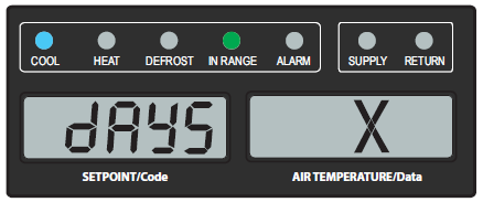
4.The display will show “dAYS”. This is the expiration time (2 through 365 in 1 day increments). Use the Arrow keys to change the parameter and press the ENTER key to confirm.
NOTE: The expiration interval is the total maximum days allowed between the running of each test. For example, if days are set to 30 and the low speed evaporator fan test has not run within those 30 days, the TripWise expired message will be displayed. If the TripWise expired message is displayed, it is recommended to Pre-Trip the unit following customer specific guidelines prior to the next trip.
Turning Off TripWise:
1.To manually turn TripWise Off, press the CODE SELECT key.
2.Use the Arrow keys to bring up Cd65 and press the ENTER key.
3.Use the Arrow keys to bring up “OFF” and press the ENTER key.
5.9.4Automatic Cold Treatment (ACT) Mode
Automated Cold Treatment (ACT) Mode is a method to simplify the task of completing cold treatment by automating the process of changing the setpoints. ACT is set up through function code Cd51. See Cd51 description for more detailed information and menu selections.
NOTE: Automatic Cold Treatment (ACT) and Automatic Setpoint Change (ASC) can not be enabled simultaneously. Setting one will deactivate the other.
Turning On and Setting ACT:
1.Press the CODE SELECT key.
2.Use the Arrow keys to scroll to Cd51, and then press the ENTER key.
3.From Cd51, use the Arrow keys to bring up "On" and press the ENTER key.
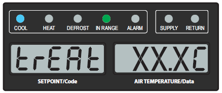
4.The display will show “trEAt | ##.#°C” with the right display flashing the last setting. Use the Arrow keys to select the desired cold treatment setpoint and press ENTER to confirm.
This is the maximum value that the USDA probes need to remain below to pass the Cold Treatment protocol. For instance, if the treat value is set at 35.0°F (1.7°C) then the USDA probe temperatures must remain below 35.0°F (1.7°C) to pass.
5.The display will show “dAyS | #” with the right display flashing the days for cold treatment. Use the Arrow keys to select the desired days and press ENTER to confirm.
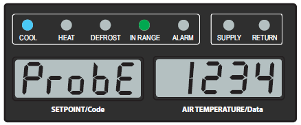
6.The display will show “ProbE | 1234” with the right display showing the probe numbers that are connected. Press ENTER.
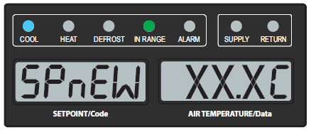
7.The display will show “SPnEW | ##.#°C” with the right display flashing the setpoint for when cold treatment process has completed. Use the Arrow keys to select the setpoint and press ENTER to confirm.
8.The Cd51 menu is returned to the top level and the display will show “Cd 51 | # #“. The right display is the countdown timer of days and hours remaining. The unit will start to countdown once all detected USDA probes have reached the specified cold treatment temperature. The countdown timer will remain in the Cd51 display until the cold treatment process is complete.
Turning Off ACT:
ACT will be automatically turned off when ASC, a TripStart, or a Pre-Trip is initiated.
1.To manually turn ACT Off, press the CODE SELECT key.
2.Use the Arrow keys to scroll to Cd51, and then press the ENTER key.
3.From Cd51, ese the Arrow keys to bring up "Off" and press the ENTER key.
5.9.5Automatic Setpoint Change (ASC) Mode
Automatic Setpoint Change (ASC) allows up to 6 setpoint changes to be pre-programmed over defined periods of time using function code Cd53. See Cd53 description for more detailed information and menu selections.
NOTE: Automatic Setpoint Change (ASC) and Automatic Cold Treatment (ACT) and can not be enabled simultaneously. Setting one will deactivate the other.
NOTE: Before starting this procedure, be aware that inaction to confirm a menu selection in a timely fashion will result in the procedure being stopped and the menu will return to the top level.
Turning On and Setting ASC:
1.Press the CODE SELECT key.
2.Use the Arrow keys to bring up Cd53 and press the ENTER key.
3.From Cd53, use the Arrow keys to scroll to ON and press the ENTER key.
4.The display will show “nSC | “#”, where # is the number of setpoint changes.
For example, if 3 setpoints are chosen, 2 setpoints will be established along with associated days that they are to be active. Then, the 3rd setpoint is chosen for the temperature desired after this procedure is complete
5.Use the Arrow keys to select the desired number (1-6) and press ENTER to confirm.
6.The display will show “SP 0 | #.#°C”, where # is the desired setpoint temperature. This is the first setpoint to be programmed.
7.Use the Arrow keys to select the desired setpoint and press ENTER to confirm.
8.The display will show “dAY 0 | #”, where # is the amount of days to keep this setpoint active.
9.Use the Arrow keys to select the desired number of days (1-99) and press ENTER to confirm.
10.The display will return back to “SP # | #.#°C”.
11.If there was more than 1 programmed setpoint chosen (nSc value), then the process will repeat itself of selecting a setpoint along with days to run that setpoint. Repeat steps 7-10 for all setpoints.
If there are no more programmed setpoints, then this last setpoint will be for unit temperature after ASC has completed. Continue to the next step.
12.Use the Arrow keys to select the setpoint after completion and press ENTER to confirm.
13.The Cd53 menu is returned to the top level and the display will show “Cd 53 | 0 0“. Upon exiting Cd53 and then returning, the display will now show “Cd 53 | # #“, where the right display is the countdown timer of days and hours remaining.
14.While ASC Mode is in progress, the user can choose to view only the settings chosen for ASC. Once at Cd53, “On” is flashing. Press ENTER and then continue to press ENTER to toggle through all of the current selections. No edits will be allowed.
15.While ASC Mode is in progress, the user can choose to edit the settings for the ASC Mode currently in progress. Once at Cd53, “On” is flashing. Use the arrow keys to display “OFF” and press ENTER. Then, use Arrow keys to select “On” and press ENTER. The procedure will start over to create settings for ASC mode. Repeat this procedure starting at step 4.
Turning Off ASC:
ASC will be turned off automatically when ACT, a Trip Start, or a Pre-Trip is initiated.
1.To manually turn ACT off, press the CODE SELECT key.
2.Use the Arrow keys to bring up Cd53 and press the ENTER key.
3.From Cd53, use the Arrow keys to bring up “OFF” and press the ENTER key.
4.The Cd53 menu is returned to the top level and the display will show “Cd 53 0 0“.
Pharma Mode, controlled with function code Cd75, is an option that allows cargoes to be maintained at temperature setpoints of either 5°C (41°F) or 20°C (68°F), while maintaining lower humidity levels. See Cd75 description for detail information of Pharma Mode menu selections and operation.
Turning On Pharma Mode:
1.Press the CODE SELECT key.
2.Use the Arrow keys to bring up Cd75 and press the ENTER key.
3.From Cd75, use the Arrow keys to bring up "On" and press the ENTER key.
4.The display will show “Sp | 05“, where 05 is blinking. Press ENTER to select 05. Or use the Arrow keys to select “20” and press ENTER.
Turning Off Pharma Mode:
1.To manually turn Pharma Mode Off, press the CODE SELECT key.
2.From Cd75, use the Arrow keys to bring up Cd75 and press the ENTER key.
3.Use the Arrow keys to bring up “OFF” and press the ENTER key.
5.9.7EverFRESH Mode
EverFRESH is a controlled atmosphere option, setup through function code Cd71, that controls container atmosphere by supplying nitrogen and oxygen into the container space and simultaneously controlling levels of oxygen and carbon dioxide. See Cd44, Cd71 and Cd76 descriptions for detail information of EverFRESH Mode menu selections and operation.
For detailed procedures and technical information related to the EverFRESH controlled atmosphere system, refer to the T-374 EverFRESH Manual.
Turning On and Setting EverFRESH:
Turning on EverFRESH enables all EverFRESH operations and setpoints for CO2 and O2 are confirmed.
1.Press the CODE SELECT key on the keypad.
2.Use the Arrow keys until “Cd 71” is displayed, then press the ENTER key.
3.From Cd71, use the Arrow keys until “FrESh” is in the right display, then press the ENTER key.
4.The CO2 setpoint is displayed. “CO2SP” appears in the left display with the setpoint value blinking in the right display. Use the Arrow keys to change the setpoint and press ENTER to confirm. Or, just press ENTER to keep the originally displayed value.
5.Next, the O2 setpoint is displayed. “O2 SP” appears in the left display with its setpoint blinking in the right display. Use the Arrow keys to change the setpoint and press ENTER to confirm. Or, just press ENTER to keep the originally displayed value.
Turning Off EverFRESH:
Turning off EverFRESH disables all EverFRESH operations.
1.Press the CODE SELECT key on the keypad.
2.From Cd71, use the Arrow keys until “Cd 71” is displayed, then press the ENTER key.
3.Use the Arrow keys until “OFF” is displayed and press the ENTER key.