Microprocessor
4.1Temperature Control Microprocessor System
The temperature control Micro-Link 5 microprocessor system consists of a controller (control module), display module, keypad and interconnecting wiring.
The controller, shown in Figure 4.1, is fitted with power connectors, a micro USB port and short range wireless connectivity. The controller contains temperature control software and DataCORDER software. The temperature control software functions to operate the unit components as required to provide the desired cargo temperature and humidity, see Section 4.2 for details. The DataCORDER software functions to record unit operating parameters and cargo temperature parameters for future retrieval, see Section 4.7 for details.
Figure 4.1 Controller / DataCORDER Module
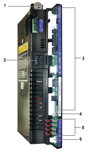
1)Mounting Screw
2)Micro USB Port
3)Wire Harness Connectors
4)Device Power Connector
5)Fuses (7.5A)
6)Controller Power Connector
- - - - -
Do not remove wire harnesses from circuit boards unless you are grounded to the unit frame with a static safe wrist strap or equivalent static drain device.
Remove the controller module and unplug all connectors before performing any arc welding on any part of the container.
When disconnecting connectors from the controller, press the latch tab prior to pulling out the connector. Damage may occur if latch tab is not pressed in prior to removing the connector.
NOTE: Do not attempt to service the controller modules. Breaking the seal will void the warranty.
4.1.2Display Module and Keypad
The display module and keypad, see Figure 4.2, are mounted on the control box door and serve to provide user access and readouts for both of the controller functions: temperature control and DataCORDER. The functions are accessed by keypad selections and viewed on the display module.
Figure 4.2 Display Module and Keypad
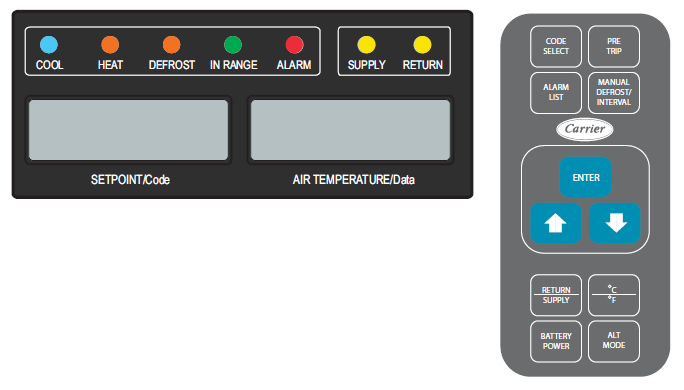
The display module consists of two 5-digit displays and seven indicator lights. Descriptions of the indicator lights are provided in Table 4–1.
The keypad consists of eleven push button switches that act as the user’s interface with the controller. Descriptions of the switch functions are provided in Table 4–2.
Table 4–1 Display Module Indicator Lights
|
Description when Energized |
|
|---|---|
|
COOL (Blue) |
Indicates that the refrigerant compressor is turned on. |
|
HEAT (Orange) |
Indicates heater operation in heat mode, defrost mode, or dehumidification. |
|
DEFROST (Orange) |
Indicates that the unit is in defrost mode. |
|
IN RANGE (Green) |
Indicates that control temperature is within the in range specified tolerance of setpoint. The controlling probe in perishable range is the supply air temperature probe. The controlling probe in frozen range is the return air temperature probe. |
|
ALARM (Red) |
Indicates an active or inactive shutdown alarm is in the alarm queue. |
|
SUPPLY (Yellow) |
When illuminated solid, it Indicates that the supply air temperature probe is being used for control during perishable mode. The temperature displayed in the AIR TEMPERATURE display is the reading at the supply air temperature probe. When flashing, it indicates that dehumidification is enabled. |
|
RETURN (Yellow) |
When illuminated solid, it Indicates that the return air temperature probe is being used for control during frozen mode. The temperature displayed in the AIR TEMPERATURE display is the reading at the return air temperature probe. |
Table 4–2 Keypad Function
|
Function |
|
|---|---|
|
CODE SELECT |
Access function codes. |
|
PRE TRIP |
Display Pre-Trip selection menu. Discontinue a Pre-Trip in progress. If TripWise is enabled, display a current TripWise status message. |
|
ALARM LIST |
Display alarm list and clear alarm queue. |
|
MANUAL DEFROST / INTERVAL |
Display selected defrost mode. Press and hold this key for five seconds to initiate defrost using same logic as if the optional manual defrost switch was toggled on. |
|
ENTER |
Confirm a selection or save a selection to the controller. |
|
Arrow Up |
Change or scroll a selection up. Pre-trip advance or test interrupt. |
|
Arrow Down |
Change or scroll selection down. Pre-trip repeat backward. |
|
RETURN SUPPLY |
Display non-controlling probe temperature (momentary display). |
|
°C °F |
Display alternate english / metric scale (momentary display). When set to F, pressure is displayed in psig and vacuum in “/hg.” “P” appears after the value to indicate psig and “i” appears for inches of mercury. When set to C, pressure readings are in bars. “b” appears after the value to indicate bars. |
|
BATTERY POWER |
Initiate battery backup mode to allow setpoint & function code selection if AC power is not connected. |
|
ALT MODE |
Access DataCORDER configuration variables, function codes and stored temperatures. Access a USB software loading menu and a wireless setup menu. |
The controller software is a custom designed program that is subdivided into configuration software and operational software. The controller software performs the following functions:
•Controls supply or return air temperature to required limits; provides modulated refrigeration operation, economized operation, unloaded operation, electric heat control, and defrost.
•Provides default independent readouts of setpoint and supply or return air temperatures.
•Provides ability to read and (if applicable) modify the configuration software variables, operating software function codes and alarm code indications.
•Provides a pre-trip step-by-step testing of refrigeration unit performance including: proper component operation, electronic and refrigeration control operation, heater operation, probe calibration, pressure limiting and current limiting settings.
•Provides battery-powered ability to access or change selected codes and setpoint without AC power connected. This is only if the carrier-provided rechargeable battery option is installed.
4.2.1Configuration Software (CnF Variables)
Configuration software is a variable listing of the components available for use by the operational software. This software is factory installed in accordance with the equipment fitted and options listed on the original purchase order. Changes to the configuration software are required only when a new controller has been installed or a physical change has been made to the unit such as the addition or removal of an option. Change to the factory-installed configuration software can be achieved via the controller micro USB port.
4.2.2Operational Software (Cd Function Codes)
The operational software is the actual operation programming of the controller which activates or deactivates components in accordance with current unit operating conditions and selected modes of operation. The programming is divided into function codes. Some of the codes are read only, while the remaining codes may be user configured. The value of the user configurable codes can be assigned in accordance with user desired modes of operation. A summary of function codes is provided in Table 4–3, and completed descriptions in Section 4.4.2.
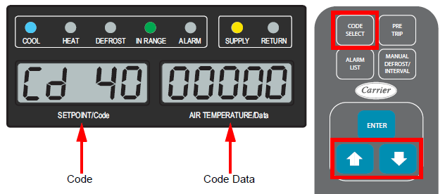
General Notes on Function Code Navigation:
1.Press the CODE SELECT key on the keypad. Then, use the Arrow keys to navigate through the function codes (Cd) in the left display. The right display shows the respective data. If the right display shows dashes “-----”, then this is an optional code not available to a particular unit configuration.
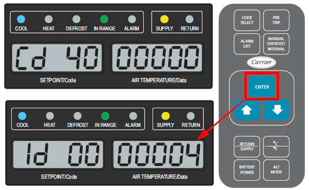
2.Press the ENTER key to navigate into the menu of a selected code. Pressing ENTER will display the present selected value for 5 seconds, or until the user selects a different value. If additional time is required, press ENTER to extend the display time to 30 seconds.
3.Press the CODE SELECT key while in a selection menu to cancel the current selection and go back up to the higher selection menu. If no key is pressed for 5 seconds, the display reverts to a normal display and the current selection menu is cancelled. Any previously committed changes are retained.
Table 4–3 Controller Function Codes (Cd) - Summary
|
Code |
Description |
Configurable |
|---|---|---|
|
Cd01 |
Capacity Modulation (%) |
|
|
Cd03 |
Compressor Motor Current |
|
|
Cd04 |
Line Current, Phase A |
|
|
Cd05 |
Line Current, Phase B |
|
|
Cd06 |
Line Current, Phase C |
|
|
Cd07 |
Main Power Voltage |
|
|
Cd08 |
Main Power Frequency |
|
|
Cd09 |
Ambient Temperature |
|
|
Cd10 |
Evaporator Temperature |
|
|
Cd11 |
Compressor Discharge Temperature |
|
|
Cd12 |
Evaporator Pressure / Compressor Suction Pressure |
|
|
Cd14 |
Compressor Discharge Pressure |
|
|
Cd15 |
Digital Unloader Valve / Digital Loader Valve |
|
|
Cd16 |
Compressor Motor / Unit Run Time Hour Meter |
|
|
Cd17 |
Relative Humidity (%) |
|
|
Cd18 |
Software Revision Number |
|
|
Cd19 |
Backup Battery Check |
|
|
Cd20 |
Config / Model Number |
|
|
Cd21 |
Capacity Mode |
|
|
Cd22 |
Compressor State |
|
|
Cd23 |
Evaporator Fan State |
|
|
Cd25 |
Compressor Run Time Remaining Until Defrost |
|
|
Cd26 |
Defrost Temperature Sensor |
|
|
Cd27 |
Defrost Interval (Hours or Automatic) |
x |
|
Cd28 |
Temperature Units (°C or F) |
x |
|
Cd29 |
Failure Action (Mode) |
x |
|
Cd30 |
In-Range Tolerance |
x |
|
Cd31 |
Stagger Start Offset Time (Seconds) |
x |
|
Cd32 |
System Current Limit (Amperes) |
x |
|
Cd33 |
Humidity Setpoint |
x |
|
Cd34 |
Economy Mode (On-Off) |
x |
|
Cd35 |
Bulb Mode |
x |
|
Cd36 |
Evaporator Fan Speed |
x |
|
Cd37 |
Variable DTT Setting (Bulb Mode) |
x |
|
Cd40 |
Container Identification Number |
|
|
Cd41 |
Valve Override |
x |
|
Cd43 |
XtendFRESH Mode |
x |
|
Cd44 |
EverFRESH Values |
|
|
Cd45 |
Vent Position Sensor (VPS) Position |
|
|
Cd46 |
Airflow Display Units |
x |
|
Cd47 |
Variable Economy Temperature Setting |
x |
|
Cd48 |
Dehumidification / Bulb Cargo Mode Parameter Selection |
x |
|
Cd49 |
Days Since Last Successful Pre-Trip |
|
|
Cd50 |
QUEST Enable / Disable |
x |
|
Cd51 |
Automatic Cold Treatment (ACT) Mode Parameter Selection |
x |
|
Cd53 |
Automatic Setpoint Change (ASC) Mode Parameter Selection |
x |
|
Cd54 |
Suction Port Superheat / Electronic Expansion Valve Status |
|
|
Cd55 |
Discharge Superheat |
|
|
Cd56 |
Enable Comms Mode |
|
|
Cd58 |
Water Pressure Switch State / Override Logic State |
|
|
Cd59 |
Pump Down Logic |
x |
|
Cd62 |
High Speed Evaporator Fan Setting |
x |
|
Cd63 |
FuelWise |
x |
|
Cd64 |
Alternate Compressor Selection PrimeLINE Edge |
x |
|
Cd65 |
TripWise |
x |
|
Cd66 |
Instantaneous Power (kW) |
|
|
Cd67 |
Energy (kW-hr) |
|
|
Cd70 |
Temperature Setpoint Lock |
x |
|
Cd71 |
EverFRESH Mode |
x |
|
Cd72 |
Air Compressor Hours Since Last Service |
x |
|
Cd73 |
Air Compressor Total Operational Hours |
x |
|
Cd74 |
Controller Diagnostic |
x |
|
Cd75 |
Pharma Mode |
x |
|
Cd76 |
CO2 Injection Mode |
x |
|
Cd77 |
Baudrate Selection |
|
|
Cd78 |
EverFRESH Air Compressor State On-Off |
|
|
Cd79 |
EverFRESH Water Drain Valve (WDV) State On-Off |
|
|
Cd80 |
EverFRESH Air Valve (EAV) State On-Off |
|
|
Cd81 |
EverFRESH CO2 Valve State On-Off |
|
|
Cd82 |
Condenser Fan State On-Off |
|
|
Cd83 |
CO2 Gas Cooler Temperature |
Cd01 displays the DUV percent closed. The right display reads 100% when the valve is fully closed. The valve will usually be at 10% on start up of the unit except in very high ambient temperatures.
Cd03 displays the current value passing through the compressor motor leg T3. The current sensor measures current draw in lines L1 & L2 by all of the high voltage components. It also measures current draw in compressor motor leg T3.
These codes display the measured of Phase A (Cd04), B (Cd05) and C (Cd06) in amperes. The current sensor measures current on two legs. The third unmeasured leg is calculated based on a current algorithm. The current measured is used for control and diagnostic purposes.
For control processing, the highest of the Phase A and B current values is used for current limiting purposes. For diagnostic processing, the current draws are used to monitor component energization.
Whenever a heater or a motor is turned ON or OFF, the current draw increase/reduction for that activity is measured. The current draw is then tested to determine if it falls within the expected range of values for the component.
Failure of this test will result in a pre-trip failure or a control alarm indication.
Cd07 displays the main supply voltage.
Cd08 displays the value of the main power frequency in Hertz. The frequency displayed will be halved if either fuse F1 or F2 is bad (alarm code AL021).
Cd09 displays the ambient temperature sensor (AMBS) reading.
Cd10 displays the evaporator temperature sensor (ETS) reading.
Cd11 Compressor Discharge Temperature
Cd11 displays the compressor discharge temperature Sensor (CPDS) reading, using compressor dome temperature.
Cd12 Evaporator Pressure / Compressor Suction Pressure
Cd12 displays the evaporator pressure transducer (EPT) reading in the right display. Press the ENTER key to show the reading for the suction pressure transducer (SPT) in the left display and the EPT in the right display.
Cd14 Compressor Discharge Pressure
Cd14 displays the compressor discharge pressure transducer (DPT) reading.
Cd15 Digital Unloader Valve / Digital Loader Valve
Cd15 displays the status of the digital unloader valve (DUV) as Open or Closed.
For PrimeLINE EDGE units (571-3xx models) the status of the digital loader valve (DLV) can also be displayed. To display the DLV status, press and hold the ENTER key for 3 seconds and continue to hold. When the key is released, the display switches back to the DUV.
Cd16 Compressor Motor / Unit Run Time Hour Meter
Cd16 displays the compressor motor hours. Press the ENTER key while in Cd16 to view unit run time. Total hours are recorded in increments of 10 hours (i.e., 3000 hours is displayed as 300).
Press and hold the ENTER key for 5 seconds to reset the Compressor Motor Hour Meter display. The Unit Run Time Hour Meter cannot be reset.
Cd17 displays the humidity sensor (HS) reading, as a percent value.
Cd18 displays the software revision number.
Cd19 runs a backup battery test and also displays results.
After selecting Cd19, press the ENTER key while “btESt” is displayed to run the backup battery test. While the test is running, “btESt” will flash on the display. Once the test is complete, the Backup Battery Test Result will be displayed. After 5 seconds, the controller returns to displaying the setpoint.
For the Test Result:
•If the test result is Pass, the display will show “PASS” to indicate this.
•If the test result is End of Life, the display will show “EOL” to indicate this.
•If the test result is Fail, the display will show “FAIL” to indicate this.
•If the test result detects a temperature out of range condition (greater than 45 deg C), the display will show “toor” to indicate this. The smart battery will not charge.
•If the test result is Non-Carrier, the display will show “not C” to indicate this.
•If the test result is No Battery, the display will show “nobAt” to indicate this.
If the ENTER key is not pressed in 5 seconds, the controller returns to displaying the setpoint.
Whenever the battery test is run, the Relative State of Charge (RSOC) is posted in the download.
Cd20 displays the dash number of the model for which the Controller is configured (i.e., if the unit is a 69NT40-571-100, the display will show “71100”).
To display controller configuration database information, press the ENTER key. Values in “CFYYMMDD” format are displayed if the controller was configured with a configuration card or with a valid OEM serial port configuration update; YYMMDD represents the publication date of the model configuration database.
Cd21 displays the mode of operation as Unloaded, Standard or Economized.
Cd22 displays the status of the compressor as OFF or On.
Cd23 displays the current state of the evaporator fan as OFF, LOW or HIGH.
Cd25 Compressor Run Time Remaining Until Defrost
Cd25 displays the time remaining until the unit goes into defrost (in tenths of an hour). This value is based on the actual accumulated compressor running time.
Cd26 Defrost Temperature Sensor
Cd26 displays the defrost temperature sensor (DTS) reading.
Cd27 Defrost Interval (Hours or Automatic)
Cd27 controls the Defrost Timer Interval, which is the desired period of time between defrost cycles. The user-selected intervals are 2, 3, 6, 9, 12, 24 Hours, Off, AUTO, AUTO2, or AUTO3. Factory default is “AUTO”. This is the desired period of time between defrost cycles. Factory default is “AUTO”. See Section 4.3.6 for information on Defrost Interval.
After a new Defrost Interval is selected, the previously selected Interval is used until the next defrost termination, the next time the DTT contacts are OPEN, or the next time power to the control is interrupted. If the previous value or the new value is “OFF”, the newly selected value will be used immediately.
If any Auto Pre-trip sequence is initiated, the defrost interval will be set to ‘AUTO’.
Unit configuration may be set so the operator is allowed to choose “OFF” as a defrost interval option.
Cd28 Temperature Units (°C or F)
Cd28 determines the temperature units (°C or F) that will be shown on all temperature values. The user selects C or F by selecting function code Cd28 and pressing the ENTER key. The factory default value is Celsius units. This function code will display “-----” if configuration variable Temperature Unit Display is set to F.
Cd29 controls the shutdown action to take if all of the control sensors are out of range (alarm code AL026) or there is a probe circuit calibration failure (alarm code AL027).
Cd29 has one of four possible actions to select as follows:
•A - Full Cooling (Compressor is on, economized operation)
•b - Partial Cooling (Compressor is on, standard operation)
•C - Evaporator Fan Only (Evaporator fans on high speed, not applicable with frozen setpoints)
•d - Full System Shutdown - Factory Default (Shut down every component in unit)
Cd30 controls the in-range tolerance, which determines the temperature band around the setpoint which will be designated as in-range. If the control temperature is in-range, the green IN-RANGE light is illuminated.
For normal temperature control, control temperature is considered in range if it is within setpoint in-range Tolerance. There are four possible values:
•1 = +/- 0.5°C (+/- 0.9°F)
•2 = +/- 1.0°C (+/- 1.8°F)
•3 = +/- 1.5°C (+/- 2.7°F)
•4 = +/- 2.0°C (+/- 3.6°F) - Factory Default
In-range tolerance shall be set to +/- 2.0°C upon activation of Dehumidification or Bulb Mode (Cd33, Cd35, Cd48).
When QUEST is actively controlling, in-range tolerance is not considered.
“-----” will be displayed whenever Dehumidification or Bulb Mode is enabled or when CCPC with six hour re-activation is actively controlling.
“-----” will be displayed whenever Frozen Economy Mode is operating.
Cd31 Stagger Start Offset Time (Seconds)
Cd31 displays the stagger start offset time, which is the amount of time that the unit will delay at start-up. This allows multiple units to stagger their control initiation when all units are powered up together.
The eight possible offset values are: 0 (Factory Default), 3, 6, 9, 12, 15, 18 or 21 seconds.
Cd32 System Current Limit (Amperes)
Cd32 displays the current limit, which is the maximum current draw allowed on any phase at any time. Limiting the unit’s current reduces the load on the main power supply. When desirable, the limit can be lowered. Note, however, that capacity is also reduced.
The five values for 460 VAC operation are: 15, 17, 19, 21, or 23 amperes, with factory default of 21 amperes.
Cd33 controls dehumidification along with setting the relative humidity value in percent that will trigger dehumidification. Relative humidity is detected with a humidity sensor (HS) and this sensor reading can be viewed at Cd17. There are configuration variables that determine whether dehumidification capabilities are installed.
Cd33 has the following values / settings:
•“XX” - lower humidity setpoint
•“dISbL” - This disables dehumidification entirely; the humidity sensor is removed from the logic. The humidity sensor configuration variable is set to OFF. This is available with software revision 6310 and higher. See the Disabling the Humidity Sensor procedure in Section 7.23.1 for detail.
•“tESt” - Dehumidification test can be run. Setpoint will be temporarily set to 1%, during the test. After 5 minutes, the normal setpoint is restored.
•“OFF” - Turns off dehumidification
•“XX” - upper humidity setpoint
If Pre-Trip Inspection is initiated, Cd33 will be set to “OFF” automatically.
If unit is configured for Enhanced Bulb Mode Interface to be active, then Cd33 will show instead Cd48 Dehumidification / Bulb Cargo Mode Parameter Selection.
Cd34 displays the current state of the Economy Mode option as “-----”, “On”, or “OFF”.
The unit’s configuration determines whether Economy Mode offered. Economy Mode is a user selectable mode of operation provided for power saving purposes.
Cd35 displays the current state of the Bulb Mode option as “-----”, “nOr”, or “bULb”.
Bulb Mode is an extension of dehumidification control (Cd33). If the unit configuration variable for dehumidification is set to “OFF,” Cd35 will display “nOr” and the user will be unable to change it. Configuration variable Enable Bulb Mode determines whether the Bulb Mode selection is offered. After a dehumidification setpoint has been selected and entered for code Cd33, the user may then change Cd35 to “bULb.” After Bulb Mode has been selected and entered, the user may then utilize function codes Cd36 and Cd37 to make the desired changes.
If Enhanced Bulb Mode configuration variable is active, then Cd35 will instead show settings for Cd48.
Cd36 sets the desired evaporator fan speed for use during the bulb Dehumidification Bulb Mode option.
This code is enabled only if Dehumidification Mode (Cd33) is “On” and Bulb Mode (Cd35) has been set to “bULb”. If these conditions are not met, “alt” will be displayed (indicating that the evaporator fans will alternate their speed) and the display cannot be changed.
If a dehumidification setpoint has been selected along with Bulb Mode then “alt” may be selected for alternating speed, “Lo” for low speed evaporator fan only, or “Hi” for high speed evaporator fan only.
If a setting other than “alt” has been selected and Bulb Mode is deactivated in any manner, then selection reverts back to “alt.”
Cd37 Variable DTT Setting (Bulb Mode)
Cd37 displays the variable defrost termination thermostat (DTT) setting to be used with the optional Bulb Mode functionality. This item is only displayed if the Bulb Mode option is configured on.
The temperature at which the DTT will be considered “open” may be changed [in 0.1°C (0.2°F) increments] to any value between 25.6°C (78°F) and 4°C (39.2°F). The temperature at which the DTT is considered closed for interval timer start or demand defrost is 10°C (50°F) for “open” values from 25.6°C (78°F) down to a 10°C (50°F) setting. For “open” values lower than 10°C, the “closed” values will decrease to the same value as the “open” setting.
Cd40 Container Identification Number
Cd40 displays the Container ID number. If a valid Container ID exists, the default display for Cd40 will be “XXXXX” where “XXXXX” is the 5th character through the 9th character of the Container ID. Press the ENTER key on Cd40 to display “id_YYYYYYY” where “YYYYYYY” is the 5th character to the 11th character of the Container ID.
If no valid Container ID exists or is blank, the default display will have Cd40 on the left display and the right display will alternate between “_nEEd” and “___id”. Press the ENTER key while on Cd40 in this state to prompt the Set Id Interface.
On start up if the Container ID is not valid, Cd40 will be brought up on the display for the first minute of power up. This can be left by either entering a container id or leaving the code select normally.
Cd41 is a Service Function. This code is for troubleshooting and allows manual positioning of the economizer solenoid valve (ESV), electronic expansion valve (EEV), and digital unloader valve (DUV).
When C41 is first displayed, the IOE communications/phase sequence detection status is displayed. When the ENTER key is pressed, navigation begins into the menu. Pressing ENTER takes the user down the menu, while pressing the CODE SELECT key goes backwards through the menu.
See Section 7.18 for detailed information regarding Cd41.
Cd43 controls the XtendFRESH controlled atmosphere option. This code will display dashes “-----” on an ML5 unit due to XtendFRESH not currently being an option for an ML5 unit.
Cd44 displays the following EverFRESH values:
•CO2 setpoint
•CO2 percentage
•O2 setpoint
•O2 percentage
•O2 voltage
•Membrane Pressure Transducer (MPT) pressure.
For detailed procedures and technical information related to EverFRESH controlled atmosphere option, refer to the T-374 EverFRESH manual.
Cd45 Vent Position Sensor (VPS) Position
Cd45 displays positional values for the vent position sensor (VPS). Values are: 0 to 240. If a unit is not configured for a VPS, dashes “-----” will be displayed.
When configured for VPS, Cd45 displays the current VPS position in units of 5 CMH (displayed as “CM”) or CFM (displayed as “CF”) depending on the selection of Cd46 (Airflow display units), Cd28 (Metric / Imperial) or the pressing of the deg C / F key.
Cd45 will display whenever the control detects movement via the VPS unless AL50 is active. Cd45 will display for 30 seconds, then time out and return to the normal display mode.
Cd46 selects the airflow units to be displayed by Cd45 if configured for Vent Position Sensor (VPS) or Autoslide.
•CF = Cubic Feet per Minute
•CM = Cubic Meters per Hour
•bOth = Displays CF or CM based on the setting of Cd28 (Metric/Imperial) or pressing of the degree C/F key.
Cd47 Variable Economy Temperature Setting
Cd47 controls the Variable Economy Temperature setting. This is applicable when configuration variable Economy Mode is set to 3-cust. Cd47 will show dashes “-----” if the unit is not configured for Economy Mode.
When the unit has a perishable setpoint and Economy Mode is active, at the start of each cooling or heating cycle, high speed evaporator fans will run for three minutes. After three minutes, the evaporator fans will be switched to low speed any time that the supply temperature is within +/- 0.25°C of the setpoint and the return temperature is less than or equal to the supply temperature + the user selected Cd47 values (0.5°C - 4.0°C, default is 3.0°C).
Cd48 Dehumidification / Bulb Cargo Mode Parameter Selection
Cd48 will initially display current Dehumidification Mode; “bUlb” (bulb cargo mode), “dEhUM” (normal dehumidification), or “OFF”.
Press the ENTER key to take the interface down into a hierarchy of parameter selection menus (mode, setpoint, evaporator speed, DTT setting). Press the ENTER key in any parameter selection menu to commit selection of the currently displayed parameter and cause the interface to descend into the next parameter selection menu. All parameter selection menus alternate between a blank display and the current selection in the right hand display.
Whenever any pre-trip test is initiated, Dehumidification Mode goes to OFF.
When Dehumidification Mode is OFF:
•Dehumidification control setpoint goes to 0% RH internally but will then initialize to 95% RH when Dehumidification Mode leaves OFF.
•Evaporator speed select goes to Alt for units configured without PWM Compressor Control, Evaporator speed select goes to Hi for units configured with PWM Compressor Control.
•DTT setting goes to 25.6°C or 18.0°C, depending on configuration setting for Enable Low DTT Setting.
When Dehumidification Mode is set to bUlb, DTT setting goes to 18.0°C if it had been set higher.
When Dehumidification Mode is set to dEhUM, DTT setting goes to 25.6°C or 18.0°C, depending on configuration setting for Enable Low DTT Setting.
For units configured without PWM Compressor Control:
•If dehumidification control setpoint is < 65% RH evaporator speed select goes to LO if it had been set to Hi.
•If dehumidification control setpoint is > 64% RH evaporator speed select goes to Alt if it had been set to LO.
For units with configured with PWM Compressor Control:
•When dehumidification control setpoint is set below 60% RH, the evaporator fan speed is set to LO, the user has the ability to set the evaporator fan speed to Hi via the keypad.
•Whenever dehumidification control setpoint is set equal to or above 60% RH, the evaporator fan speed is set to Hi, the user has the ability to set the evaporator fan speed to LO via the keypad.
Cd49 Days Since Last Successful Pre-Trip
Cd49 displays the number of days since the last successful pre-trip sequence. Press the ENTER key to view the number of days since the last successful pre-trip for AUTO1, AUTO2, and AUTO3 in sequence.
Press the CODE SELECT key to step back through the list and ultimately to exit the Cd49 display.
Cd50 enables or disables QUEST Mode, which is a power saving option that reduces energy requirements. Cd50 applies to either QUEST or QUEST II, depending on which option was chosen for the particular unit. QUEST II provides additional savings over QUEST. Configuration variables Quest Enable and Quest/Quest II Selection determine the QUEST option available for the unit.
If the unit is not configured for QUEST Mode, then dashes “-----” will be displayed.
Depending on the fan mode of operation selected, the evaporator fans may be programmed to run at low speed some of the time
Turn On QUEST Mode:
1.Select “On” and press the ENTER key to enable QUEST Mode.
When QUEST Mode is enabled:
•Setpoint is maintained in Perishable Steady State Mode after Perishable Pulldown and QUEST Pulldown are complete. During Perishable Pulldown, supply air temperature is controlled according to the unit’s nominal supply air setpoint. During QUEST pulldown, supply air temperature is lowered somewhat relative to the nominal setpoint. Evaporator fans are forced to operate at high speed.
•With QUEST, the compressor cycles on and off according to return air temperature.
•With QUEST II, the compressor and/or the heaters cycle on and off according to return air temperature.
•Dehumidification is not allowed.
QUEST Mode Suspended:
If “On” is selected, QUEST operation may be suspended as indicated by one of the suspension codes listed below. If QUEST is not “OFF” and is not suspended, “On” will be displayed.
•”SEtPt” = suspended by setpoint too low.
•”CAHUM” = suspended by CA or humidity control.
•”ACt” = suspended by ACT active.
•”FAIL” = all return temperature probe failure for QUEST.
•”PrtrP” = Pre-Trip Active.
•”C LIM” = suspended by cool limit logic.
•”PULL” = pulldown active.
•“ALArM” = suspended by shutdown alarm
Turn Off QUEST Mode:
1.Select “OFF” and press ENTER to disable QUEST Mode manually.
2.QUEST Mode is turned off automatically when any Trip Start occurs or Pre-Trip test is initiated.
Cd51 Automatic Cold Treatment (ACT) Mode Parameter Selection
Cd51 controls the Automated Cold Treatment (ACT) Mode option, which is a method to simplify the task of completing cold treatment by automating the process of changing the setpoints. Cold treatment is an effective post-harvest method to control Mediterranean and certain other tropical fruit flies.
If the unit is not configured for ACT or a valid probe setup is not detected (minimum of 3 USDA probes configured and detected), ACT can not be enabled. Cd51 will display dashes “-----”.
Cd51 initially displays the countdown timer in days and hours remaining, regardless of whether it is enabled. In the Cd51 menu, pressing the ENTER key will take the interface down into a hierarchy of parameter selections. After the last parameter selection, pressing ENTER will return to “Cd 51”.
Cd51 Parameter Selections:
•“Cd 51” | “X- X” (default “0-0”) || Countdown timer in days, hours
•“ACt” | “On” “OFF” or “----” (default “OFF“) || Enabled or disabled status
•“trEAt” | “X.X°C” (default “0.0°C“) || Cold treatment setpoint edited in increments of 0.1 degrees
•“DAyS” | “X” (default “0”) || 0 to 99 in increments of 1
•“ProbE” | “XXXX” (default “----“) || Probe positions, ex: “1234”
•“SPnEW” | “X.X°C” (default “10.0°C“) || Setpoint after ACT, edited in increments of 0.1 degrees
Turn On ACT:
1.With “ACt” displayed, select “On” and press the ENTER key to enable ACT Mode. See Section 5.9.4 for detail procedure to set ACT values using Cd51.
While ACT is On:
•The left display will flash “COLd” and the right display will flash “trEAt”, and this will alternate between the unit setpoint and control temperature at 5 second intervals. Once ACT is successful, the cargo setpoint (SPnEW setting) will be displayed in the left display and control temperature in the right display, alternating with "COLd" "Done". This will continue until ACT is turned off.
•ASC (Cd53) is disabled. ACT and ASC can not be enabled simultaneously.
•Setpoint change via the keypad is disabled.
•QUEST Mode is suspended but QUEST II can still operate.
ACT Complete:
When ACT has completed, including reaching the new setpoint, the 2nd selection in the Cd51 menu will display “done” on the left display and the MONTH DAY of completion on the right. Turning ACT off clears this entry and also resets Cd51 to initial time remaining. ACT must then be turned on to view or modify the additional parameters.
Turn Off ACT:
1.Select “OFF” and press the ENTER key to disable ACT Mode manually.
2.ACT Mode is turned off automatically when any Auto Pre-Trip test or Trip Start is initiated.
Cd53 Automatic Setpoint Change (ASC) Mode Parameter Selection
Cd53 controls the Automated Setpoint Change (ASC) Mode option, which allows up to 6 setpoint changes to be pre-programmed over defined periods. If the unit is not configured for ASC, then this will not be allowed and Cd53 will display dashes “-----”.
Cd53 initially displays the countdown timer in days and hours remaining in the right display, regardless of whether it is enabled. In the Cd53 menu, pressing the ENTER key takes the interface down into a hierarchy of parameter selections. After the last parameter selection, pressing the ENTER key will return to “Cd 53”.
Cd53 Parameter Selections:
•“Cd 53” | “X- X” (default “0-0”) || Countdown timer in days, hours
•“ASC” | “On” “OFF” or “----” (default “OFF“) || Enabled or disabled status
•“nSC” | “X” (default “1“) || Number of setpoint changes, select from 1 to 6
•“SP X” | “XX.X°C” (default “0.0°C”) || Setpoint edited in increments of 0.1 degrees
•“DAY (nSC-1)” | “X” (default “1“) || 1 to 99 in increments of 1
•“SP (nSC)” | “X.X°C” (default “10.0°C“) || Setpoint after ACT, edited in increments of 0.1 degrees.
Turn On ASC:
1.With “ASC” displayed, select “On” and press the ENTER key to enable ASC Mode. See Section 5.9.5 for detail procedure to set ASC values using Cd53.
While ASC is On:
•The left display will alternate between current unit setpoint and “ASC”. The right display will alternate between current control temperature and “ACtiV”.
•ACT (Cd51) is disabled. ASC and ACT can not be enabled simultaneously.
•QUEST Mode is suspended but QUEST II can still operate
ASC Complete:
At completion of ASC Mode, the left hand display will alternate between current unit setpoint and “ASC”. The right hand display will alternate between current control temperature and “Done”. The display will remain this way until ASC is turned off. With ASC complete, the second entry in the Cd53 menu will show “done” in the left display, and the Month / Day of completion in the right display.
Turn Off ASC:
1.Select “OFF” and press the ENTER key to disable ASC Mode manually.
2.ASC Mode is turned Off automatically when any Auto Pre-Trip test or Trip Start is initiated.
Cd54 Suction Port Superheat / Electronic Expansion Valve Status
Cd54 displays the reading for evaporator superheat (suction temperature minus suction saturation temperature as calculated from suction pressure) in the right display.
Press the ENTER key at Cd54 to show the reading for EEV position (%) in the left display.
Cd55 displays discharge superheat (discharge temperature minus discharge saturation temperature as calculated from discharge pressure) values in C / F as calculated by the discharge temperature minus the discharge saturation temperature as calculated from discharge pressure.
If this selection is not valid, dashes “-----” will be displayed.
Cd56 is only active for specific model number units that disable access to the USB port or Rear Interrogation port. Cd56 will allow access to these ports for a period of one hour.
For all other model number units that allow access to the USB and Rear Interrogation ports, Cd56 will display dashes “-----”.
An event will be posted when Comms Mode is turned On or Off.
Turn On Comms Mode:
1.With “CPort” displayed, use the Arrow keys to select “On” and press the ENTER key.
While Comms Mode is On:
•A 60 minute timer will start. During this time the user will have access to the USB and Rear Interrogation port for 60 minutes.
•The display will toggle between setpoint \ active control temperature and Cd56 “CPort ON”.
Turn Off Comms Mode:
1.With “CPort” displayed, use the Arrow keys to select “OFF” and press the ENTER key.
2.Comms Mode will be turned off automatically if the timer expires or if the unit is power cycled.
While Comms Mode is Off:
•Access to the USB and Rear Interrogation ports is disabled.
•The display will show “CPort Off” when the user selects USB in the Alt menu.
•The display reverts back to the default display.
Cd58 Water Pressure Switch State / Override Logic State
Cd58 displays “CLOSE” if the water pressure switch (WPS) contacts are closed or if these options are not installed. “OPEn” is displayed when the WPS contacts are open. When the WPS Override Logic is “TRUE”, the right display will flash.
NOTE: The CLOSE / OPEn state displayed in this code select only applies to units that have the optional water-cooled condenser with a WPS.
NOTE: The ability of the WPS Override Logic to control the condenser fan is limited. It is not possible for this logic to control the fan on units that have the WPS wired in series with the fan contactor. Units wired in this configuration can indicate that the WPS Override Logic is active by flashing the right display, however, the wiring will not allow for control of the condenser fan.
Cd59 allows operation of pump down logic control. After pressing the ENTER key at Cd59, the display will flash between “STArT” | “P dN” and “PrESS” | “EnTEr”. Press ENTER to confirm the decision for pump down logic to begin. The logic will take complete control of the unit until pump down either succeeds or fails.
After logic has been initiated, the compressor is forced off and a 5 minute timer is started. The display will flash the messages “CLOSE” | “LLV” and “PrESS” | “EnTEr”. This is a notification to close the liquid line valve (LLV) within the 5 minute time period. Once the LLV is confirmed closed, press ENTER.
The display will now read “P dN” to the left, with the current suction pressure to the right. The digital unloader valve (DUV) is locked closed and the economizer solenoid valve (ESV) open and the unit setpoint changed to -22F (for remainder of pump down) which turns the compressor On.
The pump down will complete when the unit has reached a suction pressure < 1 psig for 10 consecutive seconds. If the pump down logic completes within 25 minutes, the compressor will turn off and the display will flash between "CLOSE” | “DSV" and "PrESS” | “EnTEr". At this time, another 5 minute timer will be started. This is a notification to close the discharge service valve (DSV) within the 5 minute time period. Once the DSV is confirmed closed, press ENTER.
The unit will turn itself off and the display will notify the operator that pump down is complete by flashing messages “P dN” | “DOnE” and “SHUT” | “OFF”. The operator must then shut off the unit.
If the ENTER key is not pressed to confirm the DSV is closed within the 5 minute time period, the unit will check the current suction pressure. If the suction pressure is > 1 psig, the unit will return to pump down operation. If the suction pressure < 1 psig the unit will repeat and restart the 5 minute timer and instruct on the display to close the DSV. This will repeat until the DSV is confirmed closed with the ENTER key.
If the automatic pump down logic does not complete within 25 minutes, the unit will move to all machinery off status.
Aborting Automatic Pump Down:
After logic has been initiated, the compressor is forced off and a 5 minute timer is started. The display will flash between “CLOSE” | “LLV” and “PrESS” | “EnTEr”. During this time, the arrow keys can be pressed to switch the display message to “AborT” | “P dN” and “PrESS” | “EnTEr”. By pressing the ENTER key, power down is aborted and “P dN” | “AbrTd” flashes on the display for 5 seconds.
If the ENTER key has not been pressed to confirm that the LLV is closed within the 5 minute timer, “P dN” | “AbrTd” and “PrESS” | “EnTEr” are displayed until the operator presses any key.
NOTE: If pump down is aborted in either situation, the compressor is allowed On and the unit returns to its previous operating state.
Cd62 High Speed Evaporator Fan Setting
Cd62 allows the evaporator fan speed to be forced to high while temperature control is being performed in the perishable setpoint range. When set to “On”, evaporator fans operate in high speed regardless of any other active option that can control evaporator fan speed.
Following a power cycle, the state of the function select code is retained at its state prior to the power cycle. If “On”, this function select code will be set to “OFF” when any Trip Start occurs or any pre-trip test is initiated.
Cd63 controls FuelWise Mode, which is an option that saves energy while operating in the perishable setpoint range. When operating in the frozen setpoint range, Frozen Economy Mode complements FuelWise.
NOTE: FuelWise was previously referred to as Enhanced Economy Mode.
If the unit is not configured for FuelWise, then this will not be allowed and Cd63 will display dashes “-----”.
Following a power cycle, the state of the function select code is retained at its state prior to the power cycle if configuration variable for FuelWise Mode is set to Default ON else if set to Default OFF this will be set to OFF.
Turn On FuelWise:
1.Select “On” and press the ENTER key to enable FuelWise Mode.
Turn Off FuelWise:
1.Select “OFF” and press ENTER to disable FuelWise Mode manually.
2.FuelWise Mode is turned off automatically when any Trip Start occurs or Pre-Trip test is initiated.
Cd64 Alternate Compressor Selection PrimeLINE Edge
Cd64 allows a standard PrimeLine compressor to be installed in a PrimeLine with EDGE model number unit. This is necessary if an Edge compressor is not available to be re-installed in a unit.
When “Std” is selected The Minimum allowable capacity ratio will be set to 10%, Standard PrimeLine current limiting logic will be utilized, the original PrimeLine P6-7 test will be used during PreTrip, and the DLV will remain de-energized.
“-----” will be displayed if the unit is not a PrimeLINE EDGE unit (571-3xx models).
Cd65 controls TripWise Mode, which is an option that can run software logic to check whether a standard Pre-trip Inspection (PTI) is needed and skip unless necessary.
If the unit is not configured for TripWise, then this will not be allowed and Cd65 will display dashes “-----”.
A TripWise event is logged when TripWise is enabled, disabled or status is logged.
Components Checked During TripWise:
•Alarm Presence, RMU Presence, Compressor Test, Temperature Control, Compressor Current, Condenser Motor Current, Evaporator Motor Current, Heater Current
•Defrost Temperature Sensor (DTS), Evaporator Pressure Transducer (EPT), evaporator temperature sensor (ETS), Humidity Sensor (HS), Return Sensors (RRS / RTS), Supply Sensors (SRS / STS), Suction Pressure Transducer (SPT), Discharge Pressure Transducer (DPT), Discharge Temperature Sensor (CPDS)
•Electronic Expansion Valve (EEV), Economizer Expansion Valve (EXV), Digital Unloader Valve (DUV)
Turn On TripWise:
1.Select “On” and press the ENTER key to enable TripWise Mode. See Section 5.9.3 for detail procedure to set TripWise values using Cd65.
Turn Off TripWise:
1.Select “OFF” and press the ENTER key to disable TripWise Mode manually.
Checking TripWise Status:
To check the status of the container, press the PRE-TRIP key on the keypad. The message “SELCt | PrtrP” will appear on the display module, alternating with one of the following TripWise status messages.
•“trIPW” | “OFF”. The TripWise option is turned off.
•“trIPW” | “EX” (Expired). It is recommended to pre-trip the unit prior to the unit's next trip following customer-specific guidelines.
•“trIPW” | “PASS”. The container should be ready for use after the operator has conducted a visual inspection. Standard PTI is not required.
•“trIPW” | “CHECK”. If any TripWise test(s) execute and do not meet the pass / fail requirements, It is recommended to pre-trip the unit following customer-specific guidelines prior to the unit's next trip.
Cd66 displays real power (in kW) currently being used by the system.
Cd67 displays energy used by the system, in kW-hrs, since the last Trip Start.
Cd70 Temperature Setpoint Lock
Cd70 enables or disables the Temperature Setpoint Lock feature. When set to “On”, this will prevent setpoint change from the keypad. The default setting is “OFF”. An event will be recorded in the DataCorder each time an action is taken at Cd70.
Turn On Setpoint Lock:
1.Press the ENTER key. Use the Arrow keys to select “On” and press ENTER to confirm.
If Cd70 is set to “On” and a setpoint change is attempted with the keypad, “SPLk” | “On” is displayed for five seconds to show that setpoint lock is turned On.
Turn Off Setpoint Lock:
1.Press the ENTER key. Use the Arrow keys to select “OFF” and press ENTER to confirm.
2.Cd70 will automatically be set to “OFF” with the selection of PTI or a TripStart on the unit.
Cd71 controls the EverFRESH controlled atmosphere option. If a unit does not have the EverFRESH option, or if a temperature setpoint below -1°C (30.2°F) is selected, dashes “-----” will be displayed and this menu will not be accessible.
Cd71 contains three selectable modes of operation:
•“FrESh” - All EverFRESH operations are enabled and setpoints for CO2 and O2 can be edited.
•“OFF” - All EverFRESH operations are disabled.
•“PUrgE” - EverFRESH operations are suspended while pre-charging gas levels in the container. All EverFRESH control actions and alarm 929 is suspended in order to purge the container to a desired gas concentration.
When Fresh Mode is active, the display will toggle between the message “FrESH” | “ACtiV” and the setpoint (left) with supply or return temperature (right).
When Purge Mode is active, the display will toggle between the message “PUrgE” | “XX” (time remaining) and the setpoint (left) with supply or return temperature (right).
See Section 5.9.7 for enabling or disabling EverFRESH modes.
Detailed procedures and technical information related to the EverFRESH controlled atmosphere system can be found in the T-374 EverFRESH Manual. This can be found in the ContainerLINK™ app or from the Literature section of the Container Refrigeration website.
NOTE: If EverFRESH is installed and Cd71 is OFF, the CO2 and O2 readings will display as OFF in the data download.
Cd72 Air Compressor Hours Since Last Service
Cd72 displays the total hours of air compressor run time since last service. When the timer exceeds 5000 hours since last reset, the display will cycle the message “CA” “ChECk” until the timer is reset again. If a unit does not have the EverFRESH option, Cd72 displays dashes “-----”.
Press the ENTER key at “Cd 72” “ACHrS” to enter the menu with the following selections in the right display:
•“####” - Number of hours of air compressor run time since service.
•“rESEt” - Prompt to reset the hours. Press the ENTER key for five seconds to reset the counter to 0.
Cd73 Air Compressor Total Operational Hours
Cd73 displays the total number of operational hours for the EverFRESH system and air compressor. The total hours are displayed in increments in 10 hours (i.e. 3000 hours will be displayed as 300). If a unit does not have the EverFRESH option, Cd73 displays dashes “-----”.
Press the ENTER key at “Cd 73” “ACHrS” to enter the menu with the following selections in the right display:
•“####” - Number of hours of total air compressor run time.
•“rESEt” - Prompt to reset the hours. Press the ENTER key for five seconds to reset the counter to 0.
Cd74 is for running a Controller Self Diagnostic test. After selecting CD74, press the ENTER key while “tESt” is displayed to run the test. While the test is running, “tESt” will flash on the display. Once the test is complete, the Test Result will be displayed. After 30 seconds, the controller returns to displaying the setpoint.
Four Test Result Messages are possible:
•"PASS" - all power sources present and at the correct level, no input faults, and all output tests pass.
•"FAIL0" - a power source is not available or not at the correct level.
•"FAIL1" - all power sources present and at the correct level, but there is an input fault.
•"FAIL2" - all power sources present and at the correct level, there are no input faults, but an output test fails.
Cd75 controls the Pharma Mode option, which allows cargoes to be maintained at temperature setpoints of either 5°C (41°F) or 20°C (68°F), while maintaining lower humidity levels.
Pharma Mode is an available option for units that have installed software versions 6318 or higher and a humidity sensor that has not been disabled. If not available, Cd75 will show dashes “-----”.
Turn On Pharma Mode:
1.Select “On” and press the ENTER key. Use the Arrow keys to choose your selected setpoint of “05” or “20” and then press ENTER to confirm.
While Pharma Mode is On:
•The left display toggles between Pharma setpoint and "PhArM". The right display shows the return temperature sensor (RTS) reading.
•The controller maintains return air temperature at setpoint, the yellow RETURN indicator light is illuminated.
•The unit operates in a normal perishable mode, while disabling any power saving features such as QUEST, etc.
•Keypad entries such as MANUAL DEFROST, PRE-TRIP and setpoint temperature change are locked out. If setpoint temperature change is attempted, then display will show "SpLK” | “On".
•Function codes related to operating modes are disabled and show dashes "-----" (Cd33, Cd34, Cd35, Cd36, Cd37, Cd41, Cd48 Cd50, Cd51, Cd53 Cd63, Cd65).
Turn Off Pharma Mode:
1.To disable Pharma Mode manually, use the Arrow keys to select “OFF” and press ENTER to confirm.
Cd76 enables or disables CO2 Injection Mode. This is an option to EverFRESH controlled atmosphere system that allows CO2 to be actively injected into the cargo space during transport. If a unit does not have EverFRESH, or if EverFRESH is installed but Cd71 EverFRESH Mode is not set to FrESh, dashes “-----” will be displayed.
Cd76 contains two selectable modes of operation along with disabling (OFF):
•“A-CO2” - CO2 injection enabled with A-CO2 logic.
•“PrCON” - CO2 injection enabled with PrCON logic.
•“OFF” - CO2 injection is disabled.
When A-CO2 Mode is active, the display will toggle between the message “FrESH” | “A-CO2” and the setpoint (left) with supply or return temperature (right).
When PrCON Mode is active, the display will toggle between the message “FrESH” | “PrCON” and the setpoint (left) with supply or return temperature (right).
Detailed procedures and technical information related to the EverFRESH controlled atmosphere system can be found in the T-374 EverFRESH Manual. This can be found in the ContainerLINK™ app or from the Literature section of the Container Refrigeration website.
Cd77 displays the communication baud rate data transfer speed via RMU port between telematics and the ML5 controller. The default is set to 9600.
Cd78 EverFRESH Air Compressor State
Cd78 displays the state of the EverFRESH Air Compressor as On or OFF. If a unit does not have the EverFRESH option, dashes “-----” will be displayed. This code has no sub menu.
Cd79 EverFRESH Water Drain Valve (WDV) State
Cd79 displays the state of the EverFRESH Water Drain Valve (WDV) as On or OFF. If a unit does not have the EverFRESH option, dashes “-----” will be displayed. This code has no sub menu.
Cd80 EverFRESH Air Valve (EAV) State
Cd80 displays the state of the EverFRESH Air Valve (EAV) as On or OFF. If a unit does not have the EverFRESH option, dashes “-----” will be displayed. This code has no sub menu.
Cd81 EverFRESH CO2 Valve State
Cd81 displays the state of the EverFRESH CO2 Valve as On or OFF. If a unit does not have the EverFRESH option, dashes “-----” will be displayed. This code has no sub menu.
Cd82 displays the state of the condenser fan as On or OFF. This code has no sub menu.
General operation sequences for cooling, heating and defrost are provided in the following sub-sections. Operational software responds to various inputs. These inputs come from the temperature sensors and pressure transducers, the temperature setpoint, configuration variables settings and function code assignments. The action taken by the operational software changes as the input values change. Overall interaction of the inputs is described as a “mode” of operation. The modes of operation include perishable (chill) mode and frozen mode. Descriptions of the controller interaction and modes of operation are provided in the following sub-sections.
4.3.1.1 Start Up - Compressor Phase Sequence
At start up, the controller logic checks for proper phase sequencing and compressor rotation. If incorrect sequencing is causing the compressor and three-phase evaporator fan motors to rotate in the wrong direction, the controller will energize or de-energize relay TCP as required. Relay TCP will switch its contacts, energizing or de-energizing relays PA and PB. Relay PA is wired to energize the circuits on L1, L2 and L3. Relay PB is wired to energize the circuits on L3, L2, and L1, thus providing reverse rotation.
4.3.1.2 Start Up - Compressor Bump Start
At start up, the controller logic will initiate a compressor bump start procedure to clear liquid refrigerant from the compressor. If suction and discharge pressures have equalized, the compressor will perform three compressor bump starts. A compressor bump start may also occur after a defrost cycle has been completed.
4.3.2Perishable Mode Temperature Control
Perishable Mode is active with any perishable setpoint entered on the unit display that is above either -10°C (+14°F) or -5°C (+23°F). This is dependent on the setting in the Heat Lockout Temperature configuration variable. In Perishable Mode, the controller maintains the supply air temperature at setpoint, based on readings from the supply temperature sensor (STS). If the STS fails, the supply recorder sensor (SRS) serves as the controlling sensor. See Section 3.7.1 for location of the supply air temperature sensors.
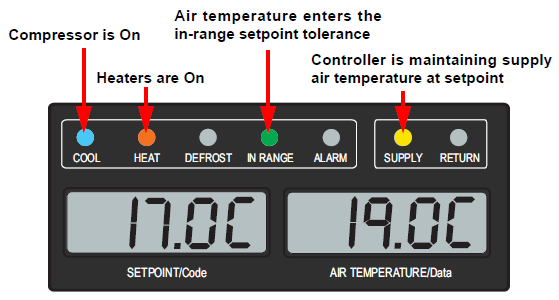
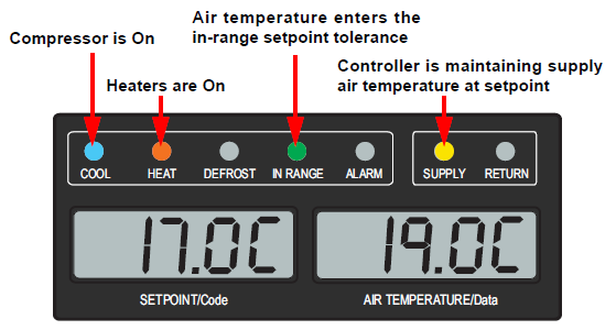
The unit display window and indicator lights react to Perishable Mode as follows. This is shown in Figure 4.3.
•The reading in the right display window is the reading from the supply air temperature sensor.
•The yellow SUPPLY indicator light illuminates to show that supply air temperature is controlling.
•The green IN-RANGE light illuminates when supply air temperature enters the in-range temperature tolerance (set at Cd30). This is the temperature band around the setpoint which is designated as in-range.
•The blue COOL light illuminates to show that the compressor is on.
•The orange HEAT light illuminates to show that the heaters are on.
Figure 4.3 Perishable Mode - Display and Indicator Lights
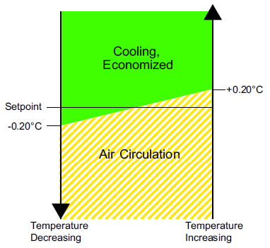
The Perishable Modes of operation are described in the following paragraphs. Figure 4.4 is provided below to illustrate the perishable modes after a setpoint is selected on the unit display.
Figure 4.4 Perishable Mode - Setpoint Temperature Control
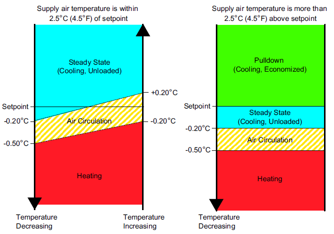
Perishable Pulldown Mode is only enabled if supply air temperature is greater than 2.5°C (4.5°F) above setpoint. The highest priority is given to bringing the container down to setpoint. The unit will cool with the compressor on, condenser fan on and the evaporator fans on and at high speed. The heaters are off. The controller will activate economized operation if it has the capability and does not exceed current or discharge pressure limits.
As supply air temperature reaches setpoint, the mode changes to Perishable Steady State Mode.
4.3.2.2 Perishable Steady State
Perishable Steady State Mode is enabled when:
•Supply air temperature is higher than setpoint but within 2.5°C (4.5°F) of setpoint.
•Supply air temperature rises +0.2°C (0.4°F) above setpoint.
•The unit was in Perishable Pulldown Mode and supply air temperature has been brought down to setpoint, so full capacity is no longer needed.
During Perishable Steady State Mode, unloaded cooling operation is activated. The controller energizes the Digital Unloader Valve (DUV) to limit capacity and maintain steady temperature control. The compressor is on and the evaporator fans are on and at high speed. The heaters are off. The unit is capable of maintaining supply air temperature to within +/- 0.2°C (+/- 0.36°F) of setpoint.
4.3.2.3 Perishable Idle / Air Circulation
The unit enters Perishable Idle Mode when the compressor is not necessary to maintain control temperature. The controller has determined that cooling is not required or the controller logic determines suction pressure is at the low pressure limit. The compressor is off but evaporator fans remain on to circulate air throughout the container.
If temperature rises +0.2°C (0.4°F) above setpoint, the unit will transition back to Perishable Steady State Mode.
The unit will transition to Perishable Heating Mode if the temperature drops to 0.5°C (0.9°F) below setpoint. The heaters are turned on. The evaporator fans remain on and at high speed to circulate air.
When the temperature rises to 0.2°C (0.4°F) below the setpoint, the unit will transition back to Perishable Idle Mode, and the heaters will turn off. The evaporator fans remain on to circulate air.
If the system capacity has been decreased to the lowest allowable capacity and conditions exist that warrant maximum temperature stability, the controller will pulse the HR relay to energize the evaporator heaters in sequence with the compressor digital signal. This is referred to as Trim Heat.
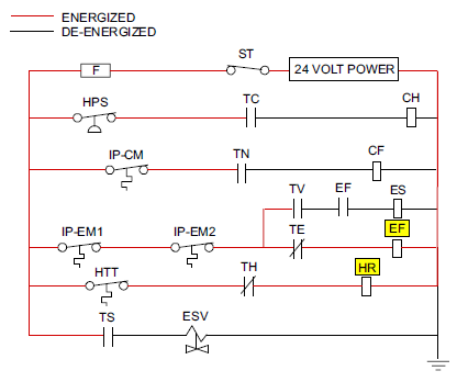
4.3.2.5 Perishable Mode Cooling - Sequence of Operation
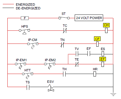
a.When supply air temperature is above setpoint and decreasing, the unit will cool with the compressor motor (CH), condenser fan motor (CF) and evaporator fan motors (EF) energized. See Figure 4.5.
Figure 4.5 Perishable Cooling Schematic - CH, CF, EF Energized
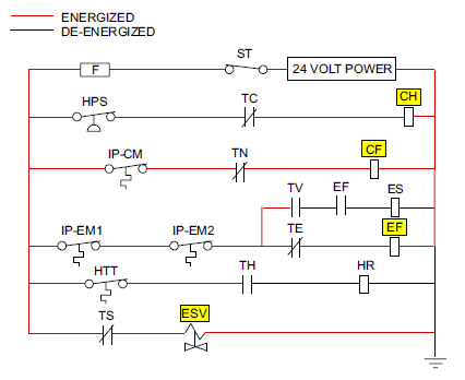
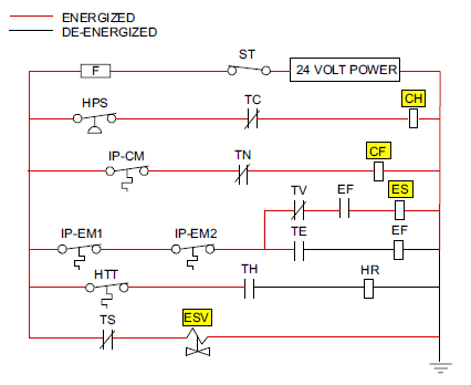
b.If current or pressure limiting is not active, the controller will close contacts TS to open the Economizer Solenoid Valve (ESV) and place the unit in economized operation. See Figure 4.6.
Figure 4.6 Perishable Cooling Schematic - ESV Open, Economized Mode
c.When supply air temperature decreases to a predetermined tolerance above setpoint (set at Cd30), the green IN RANGE light is illuminated.
d.As air temperature continues to fall, unloaded cooling starts (DUV pulses opens) as the supply air temperature approaches setpoint. When unloaded cooling starts, EEV control will transition from a full cool superheat setpoint to a lower modulated cool superheat setpoint. Once unloading starts, the EEV controls evaporator superheat based on the system duty cycle where instantaneous superheat will vary.
e.When the supply air temperature has fallen to within 1.9°C (3.4°F) of setpoint temperature and the average capacity of the system has fallen below 70%, the unit will open contacts TS to close the ESV and take the unit out of economized operation.
f.The controller continuously monitors supply air temperature. Once the supply air temperature falls below setpoint, the controller periodically records supply air temperature, setpoint and time. A calculation is then performed to determine temperature drift from setpoint over time. If the calculation determines that cooling is no longer required, contacts TC and TN are opened to de-energize the compressor motor and the condenser fan motor. In addition the controller will close the EEV.
g.The evaporator fan motors continue to run to circulate air throughout the container. The green IN RANGE light remains illuminated as long as the supply air temperature is within tolerance of the setpoint.
h.If the supply air temperature increases to 1.0°C (1.8°F) above setpoint and three minutes have elapsed, contacts TC and TN close to restart the compressor and condenser fan motors in standard mode (non-economized) operation.
i.If the average system capacity has risen to 100% during unloaded cooling and three minutes off time has elapsed, relay TS will energize to open the ESV, placing the unit in economized mode.
j.If the supply air increases more than 2.5°C (4.5°F) above setpoint temperature, the microprocessor will transition the evaporator superheat control from modulation back to full cool control.
4.3.2.6 Perishable Mode Heating - Sequence of Operation
a.If the supply air temperature decreases 0.5°C (0.9°F) below setpoint, the system enters Heating Mode. The controller closes contacts TH to allow power flow through the heat termination thermostat (HTT) to energize the heaters (HR). The evaporator fans remain On to circulate air throughout the container. See Figure 4.7.
Figure 4.7 Perishable Heating Schematic - HR, EF Energized
b.When the supply air temperature rises to 0.2°C (0.4°F) below setpoint, contact TH opens to de-energize the heaters. The evaporator fans remain On to circulate air throughout the container.
c.The safety HTT is attached to an evaporator coil circuit and will open the heating circuit if overheating occurs.
4.3.3Perishable Mode - Modes and Options
While Perishable Mode is active, there are several additional modes and options available. These are selectable from various function codes on the unit display.
4.3.3.1 Perishable Dehumidification
Perishable Dehumidification is provided to reduce the humidity levels inside the container. This mode is active if the humidity in the container is above the humidity setpoint set at code Cd33 and dehumidification is not OFF or disabled (dISbL) in Cd33.
The yellow SUPPLY LED will flash ON and OFF every second to indicate that Dehumidification is active. Once active, the controller will activate the heat relay to begin Dehumidification if the following conditions are satisfied:
•The humidity sensor (HS) reading is within setpoint range.
•Perishable Steady State Mode is active and supply air temperature is less than 0.25°C (0.45°F) above setpoint.
•The heater debounce timer (three minutes) has not timed out.
•The heater termination thermostat (HTT) is closed.
If the above conditions are true for at least one hour, the evaporator fans will switch from high speed to low speed. Evaporator fan speed will then switch every hour, as long as the four conditions are met. See Bulb Mode, Section 4.3.3.2, for different evaporator fan speed options.
If any condition except item (1) becomes false OR if the relative humidity sensed is 2% below the dehumidification setpoint, the high speed evaporator fans will be energized.
During dehumidification, power is applied to the defrost heaters. This added heat load causes the controller to open the electronic expansion valve (EEV) to match the increased heat load while still holding the supply air temperature very close to the setpoint.
Opening the EEV reduces the temperature of the evaporator coil surface, which increases the rate at which water is condensed and removes water from the passing air. Removing water from the air reduces the relative humidity. When the relative humidity sensed is 2% below setpoint, the controller de-energizes the heat relay. The controller will continue to cycle heating to maintain relative humidity below the selected setpoint. If dehumidification is terminated by a condition other than the humidity sensor, e.g., an out-of-range or compressor shutdown condition, the heat relay is de-energized immediately.
Two timers are activated during dehumidification to prevent rapid cycling and consequent contactor wear:
•Heater debounce timer (three minutes) - The heater debounce timer is started whenever the heater contactor status is changed. The heater contactor remains energized (or de-energized) for at least three minutes even if the setpoint criteria are satisfied.
•Out-of-range timer (five minutes) - The out-of-range timer is started to maintain heater operation during a temporary out-of-range condition. If supply air temperature remains outside of the user selected in-range setting for more than five minutes, the heaters will be de-energized to allow the system to recover. The out-of-range timer starts as soon as temperature exceeds in-range tolerance value set by Cd30.
4.3.3.2 Perishable Dehumidification - Bulb Mode
Bulb Mode is an extension of Perishable Dehumidification which allows changes to the evaporator fan speed and/or defrost termination setpoints. Bulb Mode is active when code Cd35 is set to “Bulb.” When Bulb Mode is active, changes can be made to the evaporator fan speed using code Cd36. Default fan operation is for fan speed to alternate from low to high each hour, but this can be changed with Cd36 to constant low or constant high speed.
In addition, if Bulb Mode is active, code Cd37 may be set to override the previous Defrost Termination Thermostat (DTT) settings.
Bulb Mode is terminated when:
•Bulb Mode function code Cd35 is set to “Nor.”
•Dehumidification function code Cd33 is set to “Off.”
•The unit setpoint is changed to a frozen setpoint.
When Bulb Mode is disabled by any of the above conditions, evaporator fan operation in code Cd36 reverts to “alt” and the DTT setting in code Cd37 resets to the value determined by the Enable Low DTT Setting configuration variable.
4.3.3.3 Perishable Economy Mode
Perishable Economy Mode is an extension of Perishable Mode. This mode is a power saving option that is active when code Cd34 is set to ON. This mode is helpful for the transportation of temperature-tolerant cargo or non-respiration items which do not require high airflow for removing respiration heat.
When active, the evaporator fans will be controlled as follows:
a.At the start of each cooling or heating cycle, the evaporator fans will run in high speed for three minutes.
b.The fans are switched to low speed any time the supply air temperature is within +/- 0.2°C (0.36°F) of the setpoint and the return air temperature is less than or equal to the supply air temperature + 3°C (5.4°F).
c.The fans continue to run in low speed for one hour.
d.At the end of the hour, the fans switch back to high speed and the cycle will be repeated.
If Bulb Mode is active, Perishable Economy Mode will be overridden.
4.3.3.4 QUEST or QUEST II Mode
QUEST is a power saving option that reduces energy requirements. Quest is a method of temperature control used during Perishable Steady State cooling that cycles the compressor on and off according to return air temperature. Code Cd50 enables/disables QUEST or QUEST II (additional savings over QUEST), depending on which option was chosen for the particular unit. Configuration variables for QUEST enable and QUEST/QUEST II selection determine the QUEST option available for the unit. See code Cd50 description for details.
4.3.3.5 Automatic Cold Treatment (ACT) Mode
Automated Cold Treatment (ACT) Mode option is a method to simplify the task of completing cold treatment by automating the process of changing the setpoints. Cold treatment is an effective post-harvest method to control Mediterranean and certain other tropical fruit flies. This is controlled with code Cd51. See code Cd51 description for details.
4.3.3.6 Automatic Setpoint Change (ASC) Mode
Automated Setpoint Change (ACT) Mode option allows up to 6 setpoint changes to be pre-programmed over defined periods. This is controlled with code Cd53. See code Cd53 description for details.
FuelWise Mode is an option that saves energy while operating in the perishable setpoint range. This is enabled/disabled with code Cd63. See code Cd63 description for details.
TripWise is an option that can run software logic to check whether a standard Pre-trip Inspection (PTI) is needed and skip unless necessary. TripWise is enable/disabled with code Cd65. See code Cd65 description for details.
4.3.3.9 EverFRESH Controlled Atmosphere
EverFRESH® is a controlled atmosphere option that is able control container atmosphere by supplying nitrogen and oxygen into the container space and simultaneously controlling levels of oxygen and carbon dioxide. EverFRESH can be controlled with code Cd71.
Refer to the T-374 EverFRESH Manual for detailed procedures and technical information related to the EverFRESH controlled atmosphere system. The manual is located in the Literature section of the Container Refrigeration website. To find the manual from the Literature section, click on Options > EverFRESH.
Pharma Mode option (ML3 only for now) allows cargoes to be maintained at temperature setpoints of either 5°C (41°F) or 20°C (68°F), while maintaining lower humidity levels. Pharma Mode is active when a unit is equipped with a humidity sensor, code Cd75 is set to ON and a temperature setpoint has been chosen at Cd75. See code Cd75 description for details.
4.3.4Frozen Mode Temperature Control
Frozen Mode is active with any setpoint entered on the unit display that is below either -10°C (+14°F) or -5°C (+23°F). This is dependent on the setting chosen in the Heat Lockout Temperature configuration variable.
In Frozen Mode, the controller maintains the return air temperature at setpoint, based on readings from the return temperature sensor (RTS). If the RTS fails, the return recorder sensor (RRS) serves as the controlling sensor. See Section 3.7.2 for location of the return air temperature sensors. The highest priority is given to bringing the container down to setpoint. The system will remain in economized operation.
The unit display window and indicator lights react to Frozen Mode as follows. This is shown in Figure 4.8.
•The reading in the right display window is the reading from the return air temperature sensor.
•The yellow RETURN indicator light illuminates to show that return air temperature is controlling.
•The green IN-RANGE light illuminates when return air temperature enters the in-range temperature tolerance (set at Cd30). This is the temperature band around the setpoint which is designated as in-range.
•The blue COOL light illuminates to show that the compressor is on.
Figure 4.8 Frozen Mode - Display and Indicator Lights
The Frozen Modes of operation are described in the following paragraphs. Figure 4.9 is provided below to illustrate the frozen modes after a setpoint is selected on the unit display.
Figure 4.9 Frozen Mode - Setpoint Temperature Control
When the return air temperature is above setpoint and decreasing, the unit will transition to Frozen Economized cooling. The unit will cool with the condenser fan, compressor, economizer solenoid valve (ESV) and low speed evaporator fans. The COOL light is illuminated.
4.3.4.2 Frozen Steady State Mode
Once the frozen setpoint is reached, the unit will transition to Frozen Steady State Mode, economized cooling.
When temperature drops to setpoint minus 0.2°C (0.4°F) and the compressor has run for at least five minutes, the unit will transition to the Frozen Idle Mode. The compressor is turned off and the evaporator fans continue to run to circulate air throughout the container. If temperature rises above setpoint +0.2°C (0.4°F), the unit will transition back to the Frozen Steady State Mode.
If the temperature drops 10°C (18°F) below setpoint, the unit will transition to the Frozen “Heat” Mode. The evaporator fans are brought to high speed, and the heat from the fans is circulated through the container. The unit will transition back to Frozen Steady State Mode when the temperature rises back to the transition point.
4.3.4.5 Frozen Mode Cooling - Sequence of Operation
a.When the return air temperature is above setpoint and decreasing, the unit will transition to economized cooling with the condenser fan motor (CF), compressor motor (CH), economizer solenoid valve (ESV) and low speed evaporator fan motors (ES) energized. See Figure 4.10.
Figure 4.10 Frozen Mode Schematic
b.When supply air temperature decreases to a predetermined tolerance above setpoint (set at Cd30), the green IN RANGE light is illuminated.
c.When the return air temperature decreases to 0.2°C (0.4°F) below setpoint, contacts TC, TS and TN are opened to de-energize the compressor, economizer solenoid valve (ESV) and condenser fan motor. The electronic expansion valve (EEV) will close.
d.The evaporator fan motors continue to run in low speed to circulate air throughout the container. The green IN RANGE light remains illuminated as long as the return air is within tolerance of setpoint.
e.If return air temperature drops to 10°C (18°F) or more below setpoint, the evaporator fans switch to high speed.
f.When the return air temperature increases to 0.2°C (0.4°F) above setpoint and three minutes have elapsed, the EEV opens and contacts TC, TS and TN close to restart the compressor, open the ESV and restart the condenser fan motor.
4.3.5Frozen Mode - Modes and Options
While Frozen Mode is active, there are several additional modes and options available. These are selectable from various function codes on the unit display.
Frozen Economy Mode complements FuelWise and provides additional energy savings while operating in the frozen setpoint range. This mode is a power saving option that is active when Cd34 is set to ON. The Economy Mode configuration variable determines whether this mode is offered.
Frozen Economy Mode is active if the following conditions exist:
•Setpoint is below -15°C
•Defrost mode (Cd27) is not set to AUTO 3.
•QUEST (Cd50) is set to On. And QUEST II is configured in
When this mode is active, the system will perform normal Frozen mode operations except that the entire refrigeration system, excluding the controller, will be turned off when the control temperature is less than or equal to the setpoint -2°C (4°F). After an off-cycle period of 60 minutes, the unit will turn on the high speed evaporator fans for three minutes, and then check the control temperature. If control temperature is greater than or equal to the frozen setpoint +0.2°C (0.4°F), the unit will restart the refrigeration system and continue to cool until the off-cycle temperature criteria are met. If the control temperature is less than the frozen setpoint +0.2°C (0.4°F) the unit will turn off the evaporator fans and restart another 60 minute off-cycle.
4.3.6Defrost
Defrost is initiated to remove ice buildup from the evaporator coil which can obstruct air flow and reduce the cooling capacity of the unit. The defrost cycle may consist of up to three distinct operations depending upon the reason for the defrost or model number configuration. The first is de-icing of the coil, the second is defrost due to a probe check cycle and the third is a snap freeze process based on the unit model configuration.
•De-icing the coil consists of removing power to the cooling components (compressor, evaporator fans, and condenser fan), closing the EEV, and turning on the heaters, which are located below the evaporator coil. During normal operation, de-icing will continue until temperatures indicate that the ice on the coil has been removed, proper air flow has been restored, and the unit is ready to control temperature efficiently.
•If defrost was initiated by the probe check logic, then the Probe Check is carried out after the completion of the defrost cycle. A Probe Check is initiated only when there is an inaccuracy between the controller temperature sensors. For more information on Probe Diagnostics, see Section 5.8.
•Snap Freeze allows the system to cool for a period of time after de-icing, with the evaporator fans turned off and is only carried out if configured by model number. Snap-Freeze allows for the removal of latent de-icing heat from the evaporator coils, and freezes any remaining moisture that might otherwise be blown into the container.
Initiation of defrost is dependent on the state of the defrost temperature sensor (DTS). When the DTS senses a temperature less than 10°C (50°F), the defrost options become active and the timer is engaged for the initiation of the defrost cycle. The defrost time accumulates when the compressor is running. In the perishable mode this is the same as real time as the compressor in general runs continuously. In frozen mode the actual time necessary to count down to the next defrost will exceed the defrost interval depending on the compressor duty-cycle.
When the defrost mode is in the active state, defrost can be initiated when any one of the following additional conditions become true:
1.Manually: While in the Defrost screen, when the Manual Defrost soft key is selected, if conditions will allow for a defrost, a manual defrost is initiated. The Defrost Indicator light is lit, and the user is brought back to the Main / Default screen. If conditions are NOT allowing for a defrost, a pop up message screen appears.
2.Timer: The Defrost Interval Timer reaches the user selectable Interval. The user-selected intervals are 2, 3, 6, 9, 12, 24 Hours, Off, AUTO, or AUTO2; factory default is AUTO. Refer to Defrost Interval setting on the Trip Settings screen.
a.Automatic defrost starts with an initial defrost at three hours. The internal adjusts on the next defrost based on ice accumulation on the evaporator coil. Following a start-up or after termination of defrost, the time will not begin counting down until the DTS reading falls below 10°C (50°F). If the reading of DTS rises above termination setting any time during the timer count down, the interval is reset and the countdown starts over. The Auto defrost time is reset to three hours start time after every PTI initiation or trip start interval.
b.After a new Defrost Interval is selected, the previously selected Interval is used until the next defrost termination, the next time the DTS contacts are OPEN, or the next time power to the control is interrupted. If the previous value or the new value is “OFF”, the newly selected value will be used immediately.
3.Probe Check: If defrost is initiated due to Probe Check immediately following the defrost cycle the evaporation fans are started and run for eight minutes to stabilize the temperature throughout the container. A probe check comparison is carried out at the end of the eight minute period if any sensor is found out of calibration. At this time its alarm set is no longer used for control/reorder purposes.
4.Probe Check Logic: The logic determines that a Probe Check is necessary based on temperature values currently reported by the supply and return probes
5.Delta T Logic: If the difference between return and supply air temperature (Delta T) becomes too great indicating possible reduced airflow over the evaporator coil caused by ice buildup requiring a defrost.
a.In Perishable Pull Down Mode - Delta T increases to greater than 12°C, and 90 minutes of compressor run time have been recorded.
b.In Perishable Steady State Mode - A baseline Delta T is recorded following the first defrost cycle after steady state conditions are reached, (the unit is cooling, and the evaporator fans and heaters must remain in a stable state for a period of five minutes). Defrost will be initiated if Delta T increases to greater than 4°C above the baseline, and 90 minutes of compressor run time have been recorded.
c.In Frozen Mode - Defrost will be initiated if Delta T increases to greater than 16°C and 90 minutes of compressor run time have been recorded.
4.3.7.1 Defrost Sequence of Operations
a.When defrost is initiated, the controller closes the EEV, opens contacts TC, TN and TE (or TV) to de-energize the compressor, condenser fan and evaporator fans. The controller then closes contacts TH to supply power to the heaters. See Figure 4.11 for schematic.
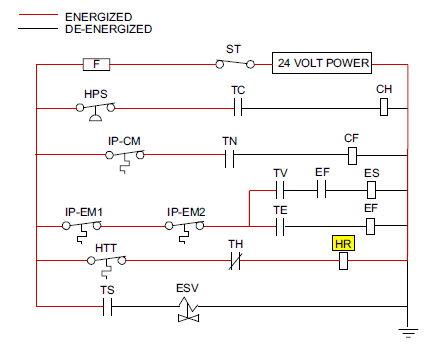
b.Defrost will terminate when the DTS reading rises above one of two model number configurable options selection, either an upper setting of 25.6°C (78°F) which is default or lower setting of 18°C (64°F). When the DTS reading rises to the configured setting, the de-icing operation is terminated.
4.3.8.1 Defrost Temperature Sensor (DTS) Failure
When the return air temperature falls to 7°C (45°F), the controller ensures that the Defrost Temperature Sensor (DTS) reading has dropped to 10°C or below. If it has not, it indicates a failed DTS. A DTS failure alarm is triggered and the defrost mode is operated by the Return Temperature Sensor (RTS). Defrost will terminate after 1 hour. If the DTS fails to reach is termination setting, the defrost terminates after 2 hours of operation.
If the Enable Defrost Interval Save configuration variable is configured to “SAv” (save), then the value of the defrost interval timer will be saved at power down and restored at power up. This option prevents short power interruptions from resetting an almost expired defrost interval, and possibly delaying a needed defrost cycle. If the save option is not selected, the defrost timer will re-initiate and begin recounting. If the Defrost “OFF” Selection configuration variable is model number configured to OFF, the operator may choose “OFF” as a defrost interval option.
If defrost does not terminate correctly and temperature reaches the set point of the heat termination thermostat (HTT) 54°C (130°F), the HTT will open to de-energize the heaters (AL259 & AL260). If the HTT does not open and termination does not occur within two hours, the controller will terminate defrost. AL260 will be activated to inform of a possible DTS failure.
4.3.9Protection Modes of Operation
4.3.9.1 Evaporator Fan Operation
Opening of an evaporator fan internal protector will shut down the unit.
4.3.9.2 Failure Action
Function code Cd29 may be operator set to select the action the controller will take upon a system failure. The factory default is a full system shutdown.
4.3.9.3 Generator Protection
Function codes Cd31 (Stagger Start, Offset Time) and Cd32 (Current Limit) may be operator set to control the start up sequence of multiple units and operating current draw. The factory default allows on demand starting (no delay) of units and normal current draw.
4.3.9.4 Compressor High Temperature Protection
The controller continuously monitors compressor discharge pressure and temperature, and suction pressure. If discharge pressure or temperature rises above the allowed limit or suction pressure falls below the allowed limit, the compressor will be cycled off and on every 3 minutes. Condenser and evaporator fans will continue to operate during the compressor off cycle.
If high compressor dome temperature occurs, as measured by the CPDS, the controller will allow additional refrigerant to be released into the system in order to provide cooling to the evaporator coil and compressor dome. The controller is alerted to high compressor dome temperatures via the CPDS when ambient temperature is greater than 43.3°C (110°F), return air temperature is less than -17.5°C (0.5°F) and the compressor discharge temperature is greater than 117.7°C (244°F). Dome temperature control logic will disengage when return air temperature and ambient temperature return to allowed limits or when the compressor turns off.
4.3.9.5 Compressor Low Pressure Protection
If the suction pressure low limit is triggered, the digital unloader valve (DUV) energizes to raise the suction pressure.
4.3.9.6 Perishable Mode System Pressure Regulation
In Perishable mode, system pressures may need to be regulated at ambient temperatures of 20°C (68°F) and below. Once below this ambient temperature, the condenser fan may cycle on and off based on limits imposed for discharge pressure. For extremely cold ambient temperatures, -18°C (0°F), heater cycling may occur within normal system operation based on discharge pressure limits.
4.3.9.7 Condenser Fan Override
When the Discharge Temperature Sensor configuration variable is set to “In” and Condenser Fan Switch Override variable is set to “On”, the condenser fan switch override logic is activated. If condenser cooling water pressure is sufficient to open the water pressure switch (de-energizing the condenser fan) when water flow or pressure conditions are not maintaining discharge temperature, the logic will energize the condenser fan as follows:
1.If the DUV is less than 80% open when the controller calls for it to be100% open, the condenser fan is energized. When the DUV is 100% open, the fan will de-energize.
2.If DPT reading is invalid or out of range (AL65), the condenser fan is energized and will remain energized until system power is cycled.
3.If the system is running on condenser fan override and the High Pressure Switch opens, the condenser fan is energized and will remain energized until the system power is cycled.
Alarm display is an independent controller software function. If an operating parameter is outside of expected range or a component does not return the correct signals back to the controller, an alarm is generated. The alarm action taken when an error is detected always considers the survival of the cargo. Rechecks are made to confirm that an error actually exists.
Some alarms requiring compressor shutdown have time delays before and after to try to keep the compressor on line. An example is alarm code “LO,” (low main voltage), when a voltage drop of over 25% occurs, an indication is given on the display, but the unit will continue to run.
A summary of alarms is provided in Table 4–4, and completed descriptions are detailed in Section 4.4.2.
NOTE: AL026 is active when none of the sensors are responding. Check the ME connector on the front of the controller. If it is loose or unplugged, reconnect it, then run a Pre-Trip test (P5) to clear AL026.
1.When a detectable problem exists, its alarm code will be alternately shown in the left display along with the setpoint. The red ALARM light illuminates for alarm code numbers 003, 017, 020 through 028 and 072.
2.The alarm list should be scrolled through to determine what alarms exist or have existed. Alarms must be diagnosed and corrected before the alarm list can be cleared.
3.On the keypad, press the ALARM LIST key, then use the Arrow keys to scroll any alarms archived in the alarm queue. The alarm queue stores up to 64 alarms in the sequence in which they occurred.
4.The left display will show “AL###,” where ### is the alarm number sequentially in the queue.
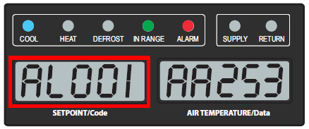
5.The right display shows the alarm code. Active alarms appear as “AA###”, with ### being the alarm code.
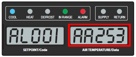
6.Inactive alarms appear as “IA###”, with ### being the alarm code.
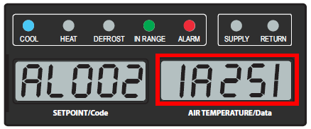
7.“END” is displayed to indicate the end of the alarm list if any alarms are active.
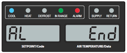
8.“CLEAR” is displayed if all alarms are inactive. Press the ENTER key to clear the alarm queue. The alarm list will clear and dashes “-----” will be displayed.
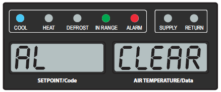
Table 4–4 Alarm Indications - Summary
|
Code |
Description |
|---|---|
|
AL003 |
Loss of Superheat Control |
|
AL017 |
Compressor Pressure Delta Fault |
|
AL020 |
Control Fuse (F3 / F4) Open |
|
AL021 |
Control Fuse (F1 / F2) Open |
|
AL022 |
Evaporator IP Open |
|
AL023 |
Loss of Phase B |
|
AL024 |
Compressor IP Open |
|
AL025 |
Condenser IP Open |
|
AL026 |
All Supply / Return Probes Failure |
|
AL027 |
Analog to Digital Accuracy Failure |
|
AL028 |
Low Suction Pressure |
|
AL072 |
Control Temp Out of Range |
|
AL098 |
Chill Injury Alarm |
|
AL205 |
Manual Defrost Switch Failure |
|
AL206 |
Keypad or Keypad Harness Fail |
|
AL207 |
Fresh Air Vent Open with Frozen Setpoint |
|
AL208 |
High Compressor Pressure Ratio |
|
AL214 |
Phase Sequence Detect Fault |
|
AL216 |
Compressor Current High |
|
AL218 |
Discharge Pressure High / Low |
|
AL219 |
Discharge Temperature High |
|
AL250 |
Air Vent Position Sensor (VPS) Fault |
|
AL251 |
Data Storage Fault |
|
AL252 |
Alarm List Full |
|
AL253 |
Battery Pack Fault |
|
AL254 |
Primary Supply Temperature Sensor (STS) Fault |
|
AL256 |
Primary Return Temperature Sensor (RTS) Fault |
|
AL257 |
Ambient Sensor (AMBS) Fault |
|
AL258 |
Compressor High Pressure Safety Open |
|
AL259 |
Heat Termination Thermostat (HTT) Open |
|
AL260 |
Defrost Temperature Sensor (DTS) Fault |
|
AL261 |
Improper Heater Current Fault |
|
AL263 |
Exceed Current Limit Setting |
|
AL264 |
Discharge Temperature Sensor (CPDS) Fault |
|
AL265 |
Discharge Pressure Transducer (DPT) Fault |
|
AL266 |
Suction Pressure Transducer (SPT), Evaporator Pressure Transducer (EPT) Fault |
|
AL267 |
Humidity Sensor (HS) Fault |
|
AL269 |
Evaporator Temperature Sensors (ETS1 / ETS2) Fault |
|
AL270 |
Supply Recorder Sensor (SRS) Fault |
|
AL271 |
Return Recorder Sensor (RRS) Fault |
|
AL272 |
USDA Temp 1 Out of Range |
|
AL273 |
USDA Temp 2 Out of Range |
|
AL274 |
USDA Temp 3 Out of Range |
|
AL275 |
Cargo Probe 4 Out of Range |
|
AL286 |
RTC Battery Low |
|
AL287 |
RTC Fault |
|
AL289 |
Data Storage Fault |
|
AL907 |
Manual Fresh Air Vent Open |
|
AL909 |
Oxygen Sensor (O2) Fault |
|
AL910 |
Carbon Dioxide Sensor (CO2) Fault |
|
AL929 |
Loss of Atmospheric Control |
|
AL962 |
Oxygen (O2) Out of Range |
|
AL976 |
Air Compressor Internal Protector Open |
|
AL977 |
Membrane Pressure Transducer (MPT) Fault |
|
AL978 |
Air Compressor Pressure Low |
|
AL979 |
Air Compressor Pressure High |
|
AL980 |
Fresh Air Valve (EA) Fault |
|
AL981 |
Water Drain Valve (WDV) Fault |
|
AL982 |
CO2 Injection Fault |
|
AL983 |
CO2 Injection Pressure Transducer Fault |
|
AL996 |
Scrubber Rotation Fault |
AL003 Loss of Superheat Control
Cause:
Superheat has remained below 1.67°C (3°F) for two to four minutes continuously while the compressor is running. The compressor is drawing more than 2.0 amps, compressor pressure ratio is greater than 1.68, and the electronic expansion valve (EEV) is at 0% open.
Component:
Electronic Expansion Valve (EEV)
Troubleshooting:
Check the operation of the EEV using Cd41. Replace the EEV if defective.
Component:
Evaporator Temperature Sensors (ETS1 & ETS2)
Troubleshooting:
Verify the accuracy of the temperature sensors. See Section 7.22, Sensor Checkout Procedure.
Replace ETS1 or ETS2 if defective.
Component:
Evaporator Fans
Troubleshooting:
Confirm that the fans are operating properly. Replace fan(s) if defective. See Section 7.10, Evaporator Fan Motor Assembly.
AL017 Compressor Pressure Delta Fault
Cause:
The compressor has attempted to start in both directions and fails to generate sufficient pressure differential between the suction pressure transducer (SPT) and discharge pressure transducer (DPT). The controller will attempt to restart every 20 minutes and deactivate the alarm if successful.
Component:
Discharge Pressure Transducer (DPT)
Troubleshooting:
Confirm accurate DPT pressure readings. Hook up the manifold gauge set to check pressures. See Manifold Gauge Set, Section 7.1.1.
Replace the DPT if defective.
Component:
Suction Pressure Transducer (SPT)
Troubleshooting:
Confirm accurate SPT pressure readings. Hook up the manifold gauge set to check pressures. See Section 7.1.1, Manifold Gauge Set.
Replace the SPT if defective.
Component:
Monitor the unit. The alarm is display only; the alarm may clear itself during operation.
Troubleshooting:
If the alarm remains active or repeats, replace the compressor at next available opportunity. See Section 7.2, Compressor Service.
Cause:
Control power fuse (F3 or F4) is open.
Component:
F3 fuse
Troubleshooting:
Check the fuse. If it is open, check PA, PB, CH coils for short to ground. If a short is found, replace the defective coil. Replace the fuse.
Component:
F4 fuse
Troubleshooting:
Check the fuse. If fuse is open, check economizer solenoid valve (ESV) coil resistance at CA1 to TRX2. If short to ground, or if resistance is less than 4 ohms, coil is defective. Check the CF, ES, EF, HR coils for short to ground. If a short is found, the coil is defective. Replace the defective coil. Replace the fuse.
Component:
Voltage at QC1
Troubleshooting:
If voltage is not present, check ST7. If voltage is present, it indicates a defective microprocessor. See Section 7.20, Controller Service.
AL021 Control Fuse (F1 / F2) Open
Cause:
One of the 18 VAC controller fuses (F1 or F2) is open. See Cd08.
Component:
System Sensors
Troubleshooting:
Check system sensors for short to ground. Replace defective sensor(s).
Component:
Wiring
Troubleshooting:
Check wiring for short to ground. Repair as needed.
Component:
Controller
Troubleshooting:
Controller may have an internal short. Replace the controller. See Section 7.20, Controller Service.
Cause:
Evaporator motor internal protector (IP) is open.
Component:
Evaporator Motor
Troubleshooting:
Shut down unit, disconnect power. Check harness between CA22 and CA12. If open circuit, check evaporator motor IP at plug connection pins 4 & 6. Replace defective evaporator fan motor. See Section 7.10, Evaporator Fan Motor Service.
Cause:
Compressor is running and controller determines that compressor internal protector and HPs are closed. Or, the high speed evaporator fan motor is energized and internal protector is not tripped and current reading is less than 0.5 amps.
Component:
Incoming Power
Troubleshooting:
Verify proper voltage input and proper operation of compressor contactor and high speed evaporator contactor. Replace defective component.
Cause:
Compressor internal protector (IP) is open.
Component:
Compressor
Troubleshooting:
Shut down unit disconnect power and check resistance of compressor windings at contactor T1-T2, T2-T3. Monitor unit, if alarm remains active or is repetitive replace the compressor at the next available opportunity. See Section 7.2, Compressor Service.
Cause:
Condenser fan motor internal protector (IP) is open.
Component:
Insufficient Air Flow
Troubleshooting:
Shut down unit and check condenser fan for obstructions.
Remove obstructions.
Component:
Condenser Fan Motor
Troubleshooting:
Shut down unit, disconnect power. Check resistance at harness between CA23 and CA11. If open, check condenser fan motor IP at plug connection pins 4 & 6. Replace defective condenser fan motor. See Section 7.5, Condenser Fan Motor Assembly Service.
AL026 All Supply / Return Probes Failure
Cause:
Sensors out of range.
Component:
All sensors detected as out of range.
Troubleshooting:
Perform pre-trip P5.
If P5 passes, no further action is required.If P5 fails, replace the defective sensor as determined by P5. See Temperature Sensor Service, Section 7.22.
AL027 Analog to Digital Accuracy Failure
Cause:
Controller AD converter faulty.
Component:
Controller
Troubleshooting:
Power cycle the unit. If the alarm persists, it indicates a defective microprocessor. Replace defective microprocessor. See Section 7.20, Controller Service.
Cause:
Suction pressure too low for normal operation.
Component:
N/A
Troubleshooting:
Power cycle the unit.
Resetting the unit may correct problem. Check charge. Monitor the unit.
Component:
Suction Pressure Transducer (SPT)
Troubleshooting:
Confirm accurate SPT pressure readings. See Section 7.1.1, Manifold Gauge Set. Replace the SPT if defective.
Component:
Discharge Pressure Transducer (DPT)
Troubleshooting:
Confirm accurate DPT pressure readings. See Section 7.1.1, Manifold Gauge Set. Replace the DPT if defective.
AL072 Control Temp Out of Range
Cause:
After the unit goes in-range for 30 minutes then out of range for a continuous 120 minutes.
Component:
Refrigeration System
Troubleshooting:
Ensure unit is operating correctly.
Power cycle the unit.
Control temperature is in range.
Any pre-trip mode resets the timers.
Cause:
When a unit is in perishable mode, it will monitor its setpoint, return probe value and compressor status. This alarm is triggered when all of the following conditions are true:
1.Setpoint > heat lockout temperature (perishable control)
2.Return Temperature Sensor (RTS) ≤ Setpoint - 4K Or Return Recorder Sensor (RRS) ≤ Setpoint - 4K Or Defrost Temperature Sensor (DTS) ≤ Setpoint - 4K
3.Supply Temperature Sensor (STS) or Supply Recorder Sensor (SRS) >= Setpoint.
4.Compressor is running (ON).
If the alarm is triggered, the unit will go into an idle state. The compressor and condenser motor will stop running. The unit will operate under air circulation mode with the evaporator motors running. The controller will continue to monitor thermistor probe value in idle state. If RRS, RTS, or DTS goes +2K above temperature control setpoint, the alarm will clear itself. Power cycling of the unit will reset the counters.
Component:
Sensors
Troubleshooting:
Run Pre-Trip test P5 to test the return recorder sensor (RRS), return temperature sensor (RTS) or defrost temperature sensor (DTS). If any sensor fails, then replace. If all sensors pass, then check the compressor.
Component:
Compressor
Troubleshooting:
Check to see why the compressor is over-shooting setpoint temperature. Run a Pre-Trip test P6 to test the compressor and related components.
AL205 Manual Defrost Switch Failure
Cause:
Controller has detected continuous manual defrost switch activity for five minutes or more.
Component:
Keypad
Troubleshooting:
Power cycle the unit.
Reset the unit to attempt to correct the problem. Monitor the unit.
If the alarm re-appears after five minutes, replace the keypad.
AL206 Keypad or Keypad Harness Fault
Cause:
Controller has detected that one of the keypad keys is continuously active.
Component:
Keypad or Harness
Troubleshooting:
Power cycle the unit.
Reset the unit to attempt to correct the problem. Monitor the unit.
If the alarm reappears, replace the keypad and harness.
AL207 Fresh Air Vent Open with Frozen Setpoint
Cause:
Unit has a frozen setpoint and vent position sensor (VPS) is indicating that the fresh air vent is open.
Component:
Vent Position Sensor (VPS)
Troubleshooting:
If unable to obtain a zero reading, replace the defective VPS.
If unit is loaded, make sure that the vent is closed. Note and replace VPS on next PTI.
AL208 High Compressor Pressure Ratio
Cause:
Controller detects discharge pressure to suction pressure ratio is too high. The controller will attempt to correct the situation by restarting the compressor.
Component:
Discharge Pressure Transducer (DPT)
Troubleshooting:
Confirm accurate DPT pressure readings. See Section 7.1.1, Manifold Gauge Set. Replace the DPT if defective.
AL214 Phase Sequence Detect Fault
Cause:
Controller is unable to determine the correct phase relationship.
Component:
N/A
Troubleshooting:
Power cycle the unit.
Reset the unit to attempt to correct the problem. Monitor the unit.
Component:
Wiring
Troubleshooting:
Check unit wiring. Confirm pressure readings during start-up. Suction pressure should decrease and discharge pressure should increase.
Correct wiring.
Component:
Current Sensor
Troubleshooting:
Check Cd41, the right-most digit. If the display is 3 or 4, check compressor / sensor wiring. If the display is 5, the current sensor is defective. Replace the current sensor if defective.
Cause:
Compressor current draw is over the calculated maximum for 10 minutes.
Component:
Current Sensor
Troubleshooting:
Compare Cd03 to actual measured current at wire T1-T2 or T3 going to the compressor contactor. If there is a difference, determine whether this is caused by the current sensor or the amp clamp tool.
Replace the current sensor if defective.
Component:
Amperage Too High
Troubleshooting:
Confirm that supply voltage / frequency is within specification and balanced according to Section 3.10, Electrical Data table.
Correct power supply.
Component:
Operating Conditions
Troubleshooting:
Make sure system pressures are relevant to operating conditions.
Check condenser air flow. Check refrigerant charge, See Section 7.1.7, Refrigeration System Service.
Component:
Monitor Unit
Troubleshooting:
The alarm is display only. The alarm may clear itself during operation.
If the alarm remains active or is repetitive, replace the compressor at the next available opportunity. See Compressor Service, Section 7.2.
AL218 Discharge Pressure High / Low
Cause:
Discharge pressure is over the maximum for 10 minutes within the last hour.
Component:
Restrictions in the refrigeration system.
Troubleshooting:
Ensure liquid line service valve is fully open.
Open liquid line service valve as needed.
Component:
Filter Drier
Troubleshooting:
Check the filter drier. If it is iced up or very cold, then the filter drier needs replacement.
Replace the filter drier if needed. See Section 7.7, Filter Drier Service.
Component:
Condenser Fan
Troubleshooting:
Check condenser fan for proper operation.
Correct as required.
Component:
Discharge Pressure Transducer (DPT)
Troubleshooting:
Confirm accurate DPT pressure readings. See Section 7.1.1, Manifold Gauge Set.
Replace DPT if defective.
Component:
Non-condensables in the refrigeration system.
Troubleshooting:
With the unit off, allow system to stabilize to ambient temperature. Check system pressure against Pressure Temperature Chart. See Table 7–4, Table 7–5.
Correct as required. See Section 7.1.7.1, Checking Refrigerant Charge.
Component:
Refrigerant
Troubleshooting:
Check refrigerant level.
Correct as required. See Section 7.1.7.1, Checking Refrigerant Charge.
AL219 Discharge Temperature High
Cause:
Discharge temperature exceeds 135°C (275°F) for 10 minutes within the last hour.
Component:
Restrictions in the refrigeration system.
Troubleshooting:
Ensure the discharge service valve is fully open. Check the unit for air flow restrictions.
Open the discharge service valve as needed. Clean or remove debris from coils.
Component:
Non-condensables in the refrigeration system.
Troubleshooting:
With the unit off allow system to stabilize to ambient temperature. Check system pressure against pressure / temperature chart. See Table 7–4, Table 7–5.
Correct as required. See Section 7.1.7.1, Checking Refrigerant Charge.
Component:
Additional Alarms such as AL216, AL024.
Troubleshooting:
Check compressor operation.
If the alarm persists, it may indicate a failing compressor, replace the compressor. See Compressor Service, Section 7.2.
AL250 Air Vent Position Sensor Fault
Cause:
The vent position sensor (VPS) reading has not been stable for four minutes. Or, the VPS is outside of its valid range (shorted or open).
Component:
Vent Position Sensor (VPS)
Troubleshooting:
Make sure the VPS is secure.
Power the unit Off. Manually tighten the panel. Turn the unit On. If the alarm persists, replace the sensor or the assembly. See Section 7.24, VPS Service Procedures.
Cause:
Controller memory failure.
Component:
Controller
Troubleshooting:
Press the ENTER key when “CLEAr” is displayed to attempt to clear the alarm.
If action is successful (all alarms are inactive), alarm 251 will reset.
Power cycle the unit. If the alarm persists, it indicates defective controller memory.
Replace defective controller. See Section 7.20, Controller Service Procedures.
Cause:
Alarm list queue is full.
Component:
Active Alarms
Troubleshooting:
Repair any alarms in the queue that are active. Indicated by “AA”.
Clear alarms. See Section 4.4, Controller Alarms.
Cause:
Any of the USDA1, USDA2, or USDA3 probes have been detected AND the Backup Battery Test Result is Failure. Or, no battery.
Component:
Battery
Troubleshooting:
Perform battery test in function code Cd19 to determine failure mode of battery.
To clear the alarm, replace the battery pack. See Section 7.20.4, Battery Replacement Procedure. If after replacement the alarm continues, run Cd19 to determine whether the replaced battery is good.
AL254 Primary Supply Temperature Sensor (STS) Fault
Cause:
Invalid Supply Temperature Sensor (STS) reading.
Component:
Supply Temperature Sensor (STS)
Troubleshooting:
Perform pre-trip P5.
If P5 passes, no further action is required. If P5 fails, replace the defective sensor as determined by P5. See Section 7.22, Temperature Sensor Service Procedures.
AL256 Primary Return Temperature Sensor (RTS) Fault
Cause:
Invalid Return Temperature Sensor (RTS) reading.
Component:
Return Temperature Sensor (RTS)
Troubleshooting:
Perform pre-trip P5.
If P5 passes, no further action is required. If P5 fails, replace the defective sensor as determined by P5. See Section 7.22, Temperature Sensor Service Procedures.
AL257 Ambient Sensor (AMBS) Fault
Cause:
Invalid Ambient Temperature Sensor (AMBS) reading.
Component:
Ambient Temperature Sensor (AMBS)
Troubleshooting:
Test the AMBS. See Section 7.22.2, Sensor Checkout Procedure.
Replace the AMBS if defective. See Section 7.22, Temperature Sensor Service Procedures.
AL258 Compressor High Pressure Safety Open
Cause:
High pressure safety switch remains open for at least one minute.
Component:
High Pressure Switch (HPS)
Troubleshooting:
Test the HPS. See Checking High Pressure Switch, Section 7.3.1.
Replace the HPS if defective. See Sensor Replacement, Section 7.22.
Component:
Refrigeration System
Troubleshooting:
Check unit for air flow restrictions.
Clean or remove any debris from coils.
AL259 Heat Termination Thermostat (HTT) Fault
Cause:
Heat Termination Thermostat (HTT) is open.
Component:
Heat Termination Thermostat (HTT)
Troubleshooting:
Check resistance between CA21 and CA10. If 0 ohms, switch closed. if infinite (OL), switch open.
Replace the HTT if defective. See Section 7.22, Temperature Sensor Service Procedures.
AL260 Defrost Temperature Sensor (DTS) Fault
Cause:
Failure of the Defrost Temperature Sensor (DTS) to open.
Component:
Defrost Temperature Sensor (DTS)
Troubleshooting:
Test the DTS. See Section 7.22.2, Sensor Checkout Procedure.
Replace the DTS if defective. See Section 7.22, Temperature Sensor Service Procedures.
AL261 Improper Heater Current Fault
Cause:
Improper current draw during heat or defrost mode.
Component:
Heater(s)
Troubleshooting:
While in heat or defrost mode, check for proper current draw at heater contactors. See Section 3.10, Electrical Data. Replace heater(s) if defective. See Section 7.9, Evaporator Heater Service.
Component:
Contactor
Troubleshooting:
Check voltage at heater contactor on the heater side. If no voltage present, replace heater contactor if defective.
AL263 Exceed Current Limit Setting
Cause:
Unit operating above current limit.
Component:
Refrigeration System
Troubleshooting:
Check unit for air flow restrictions. Clean or remove any debris from coils.
Check unit for proper operation. Repair as needed.
Component:
Power supply
Troubleshooting:
Confirm supply voltage / frequency is within specification and balanced. See Section 3.10, Electrical Data. Correct power supply.
Component:
Current limit set too low.
Troubleshooting:
Check current limit setting with function code Cd32. The current limit can be raised (maximum of 23 amps) using Cd32.
AL264 Discharge Temperature Sensor (CPDS) Fault
Cause:
Discharge Temperature Sensor (CPDS) out of range.
Component:
Discharge Temperature Sensor (CPDS)
Troubleshooting:
Test the CPDS. See Section 7.22.2, Sensor Checkout Procedure. Replace the CPDS if defective. See Section 7.22, Sensor Replacement.
AL265 Discharge Pressure Transducer (DPT) Fault
Cause:
Compressor Discharge Pressure Transducer (DPT) is out of range.
Component:
Discharge Pressure Transducer (DPT)
Troubleshooting:
Confirm accurate DPT pressure readings. See Section 7.1.1, Manifold Gauge Set. Replace the DPT if defective.
AL266 Suction Pressure Transducer (SPT), Evaporator Pressure Transducer (EPT) Fault
Cause:
Suction Pressure Transducer (SPT) or Evaporator Pressure Transducer (EPT) out of range.
Component:
Suction Pressure Transducer (SPT); Evaporator Pressure Transducer (EPT)
Troubleshooting:
Confirm accurate SPT and EPT pressure readings. See Section 7.1.1, Manifold Gauge Set. Performing a pre-trip 5-9 test will also check the transducers. Replace the SPT / EPT if defective.
Monitor. If the alarm persists, it may indicate a failing compressor. See Section 7.2, Compressor Service.
AL267 Humidity Sensor (HS) Fault
Cause:
Humidity Sensor (HS) reading out of range.
Component:
Humidity Sensor (HS)
Troubleshooting:
Make sure the HS is properly connected in the socket. Make sure the HS wires have not been damaged. Monitor, replace the HS if the alarm persists.
Monitor. If the alarm persists, it may indicate a failing compressor. See Section 7.2, Compressor Service.
AL269 Evaporator Temperature Sensors (ETS1 / ETS2) Fault
Cause:
Evaporator Temperature Sensors (ETS1 / ETS2) out of range.
Component:
Evaporator Temperature Sensors (ETS1 / ETS2)
Troubleshooting:
Test the sensors. See Section 7.22.2, Sensor Checkout Procedure. Replace evaporator temperature sensors (ETS1 / ETS2) if defective.
AL270 Supply Recorder Sensor (SRS) Fault
Cause:
Supply Recorder Sensor (SRS) is out of range.
Component:
Supply Recorder Sensor (SRS)
Troubleshooting:
Perform pre-trip P5. If P5 passes, no further action is required. If P5 fails, replace the defective sensor as determined by P5. See Section 7.22, Temperature Sensor Service.
AL271 Return Recorder Sensor (RRS) Fault
Cause:
Return Recorder Sensor (RRS) is out of range.
Component:
Return Recorder Sensor (RRS)
Troubleshooting:
Perform pre-trip P5. If P5 passes, no further action is required. If P5 fails, replace the defective sensor as determined by P5. See Section 7.22, Temperature Sensor Service.
AL272 USDA Temp 1 Out of Range Fault
Cause:
USDA Temp 1 Sensor is out of range.
Component:
Sensor
Troubleshooting:
Validate sensor values. See Section 7.22, Sensor Checkout Procedure. If the sensor is bad, replace. If not, verify harness wiring and controller connections.
AL273 USDA Temp 2 Out of Range Fault
Cause:
USDA Temp 2 Sensor is out of range.
Component:
Sensor
Troubleshooting:
Validate sensor values. See Section 7.22, Sensor Checkout Procedure. If the sensor is bad, replace. If not, verify harness wiring and controller connections.
AL274 USDA Temp 3 Out of Range Fault
Cause:
USDA Temp 3 Sensor is out of range.
Component:
Sensor
Troubleshooting:
Validate sensor values. See Section 7.22, Sensor Checkout Procedure. If the sensor is bad, replace. If not, verify harness wiring and controller connections.
AL275 Cargo Probe 4 Out of Range Fault
Cause:
Cargo Probe 4 Sensor is out of range.
Component:
Sensor
Troubleshooting:
Validate sensor values. See Section 7.22, Sensor Checkout Procedure. If the sensor is bad, replace. If not, verify harness wiring and controller connections.
Cause:
RTC Battery output low.
Component:
RTC Battery
Troubleshooting:
Power cycle unit and monitor 24 hours to verify alarm goes inactive. If the alarm stays active, replace the battery.
Cause:
RTC time invalid.
Component:
Real Time Clock
Troubleshooting:
Power cycle. Reset the clock. Verify it maintains the correct time. Replace the RTC Battery. Retest.
Cause:
Unable to store data in DataCORDER.
Component:
DataCORDER
Troubleshooting:
Power cycle and verify that the alarm goes inactive. If the alarm stays active, replace the controller.
AL907 Manual Fresh Air Vent Open
Cause:
For units equipped with EverFRESH and a vent position sensor (VPS), the controller will monitor the manual fresh air opening at a pre-determined time. If during this time the fresh air vent is open and EverFRESH is active, an alarm will be generated. If an alarm is active, the controller monitors the manual fresh air once per hour. Upon clearing the alarm, the controller goes back to monitoring at the pre-determined time.
Component:
Vent Position Sensor (VPS)
Troubleshooting:
Manually reposition vent to 0% and confirm using Cd45. If Cd45 is not reading 0%, perform a calibration of the panel. See Section 7.24 for VPS service procedures. If unable to obtain a zero reading, replace the defective VPS. If the unit is loaded, ensure the vent is closed. Note and replace the VPS on the next PTI. The alarm will not affect the EverFRESH system from operating.
AL909 Oxygen Sensor (O2) Fault
Cause:
Triggered anytime the O2 sensor reading is outside of the normal operation range, after an initial signal was detected.
Action:
EverFRESH Air Compressor (EAC) 100% duty cycle and open the EverFRESH Air Valve (EA). Will prevent low O2 and cargo loss. If both AL909 and AL910 are active, run the EAC and open the EA.
Component:
O2 Sensor, O2 Amplifier
Troubleshooting:
Check Cd44 and scroll down to 02V. The O2 sensor output will be displayed in millivolts (130mV to 4100mV is a good range). Check wiring (See schematic), and check for bad connections or wires improperly positioned.
If O2 sensor is available, remove the upper fresh air panel and evaporator motor and replace the sensor. If after replacing the sensor Cd44 reads outside of the normal range and AL909 continues, replace the amplifier.
If parts are not available, turn the EverFRESH option off via Cd71 and open the manual fresh air vent.
AL910 Carbon Dioxide Sensor (CO2) Fault
Cause:
Triggered anytime the CO2 sensor reading is outside of the normal operation range, after an initial signal was detected.
Action:
EverFRESH Air Compressor (EAC) 100% duty cycle and open the EverFRESH Air Valve (EA). Will prevent low O2 and cargo loss. If both AL909 and AL910 are active, run the EAC and open the EA.
Component:
CO2 Sensor
Troubleshooting:
Check wiring and check for bad connections or wires improperly positioned.
Check the voltage on the back of MD connectors pin MD09 (-) and MD03 (+12 VDC) with the controller energized. If 12 VDC is not available, check the controller. If 12 VDC is available, check the back of pin MD02 for a voltage between 1.0 - 4.7 VDC. If not present, replace the sensor.
If part is available, remove the upper fresh air panel and evaporator motor and replace the sensor. If no part is available, take no action and service at next PTI.
AL929 Loss of Atmospheric Control
Cause:
Triggered whenever the CO2 level is above its setpoint by 2%. Or, when the O2 level is below its setpoint for longer than 30 minutes. The alarm is triggered off when the levels return to within the normal range.
Action:
Enable Alarm LED. Open the fresh air vent and air compressor is enabled.
Verify all EverFRESH components are functioning properly by checking for EverFRESH alarms and running a P-20 PreTrip. If a component is not functioning properly, it will fail the appropriate P-20 sub test. Note components in order below.
Component:
Membrane Pressure Transducer (MPT)
Troubleshooting:
Remove the MPT. Turn on the container unit. Using Cd44, verify the MPT pressure reads between -5 and +5 psig. Outside this range or if AL977 active, replace the sensor.
Component:
EverFRESH Air Compressor (EAC)
Troubleshooting:
Verify EAC fuses FEF1, FEF2 & FEF3.
Check P20 results for a failure mode:
•Possible detected failure with EAC current consumption, check compressor motor windings, and verify voltage on all 3 phases.
•MPT failure. Follow steps above.
•Failure of AC contactor for EAC. Ohm contactor coil and check resistance across contactor legs, with power removed.
Component:
EverFRESH Air Valve (EA)
Troubleshooting:
A closed or plugged EA solenoid could prevent fresh air from entering the container. P20-2 tests the valve. Potential failure results:
•MPT pressure fails to change when the valve is energized. Check for blockage in the valve or piping.
•EA current is not correct. Access function code Cd74 and perform a ML5 self-check to verify the controller is functioning properly. If it passes, perform a ohm check on the back of CA08 pin and TRX2 (ground) using the carrier service tool (part # 22-50485-00).
Component:
Water Drain Valve (WDV)
Troubleshooting:
A closed or plugged WDV or filter housing could prevent any air from entering the container. P20-3 tests valve operation. Potential failure results:
•MPT pressure fails to change when the valve is energized. Check for signs of blockage by removing the WDV housing and particulate filter housings. Clean any debris. While removed, inspect the WDV and associated piping for blockage.
•EA current not correct. Access function code Cd74 and perform a ML5 self-check to verify the controller is functioning properly. If it fails, replace the controller. If it passes self-check, replace the WDV.
Component:
EverFRESH Nitrogen Valve (EN)
Troubleshooting:
An open or leaky EN valve would allow N2 to go into the sensor sensing chamber causing an inaccurate reading. P20-5 tests this valve. Potential failure results:
•If tests fail, remove the EN and verify the valve is not clogged or damaged.
•EA current is not correct. Access function code Cd74 and perform a ML5 self-check to verify the controller is functioning properly. If it fails, replace the controller. If it passes self-check, replace the EN.
AL962 Oxygen (O2) Out of Range
Cause:
This is a notification alarm and does not pose a risk to fresh produce, however the benefit of atmosphere control will not be lost. O2 level reaches pulldown limit and then O2 exceeds 5% over setpoint for 30 minutes.
Component:
Upper Fresh Air Panel
Troubleshooting:
Verify the Upper Fresh Air Panel has not been opened.
Component:
EverFRESH Air Valve (EA)
Troubleshooting:
An EA that is stuck open can allow continuous flow of fresh air into the container when the compressor is on. See troubleshooting in the AL929 section.
Component:
Container Air Tightness
Troubleshooting:
Seal container where possible (access panels, rear doors, mounting hardware, etc)..
AL976 Air Compressor Internal Protector Open
Cause:
EverFRESH Air Compressor (EAC) internal protector opens.
Component:
EverFRESH Air Compressor (EAC)
Troubleshooting:
Follow steps defined in AL929 EAC testing.
Component:
ML5 Controller
Troubleshooting:
Access function code Cd74 to perform an ML5 self-diagnostic test.
AL977 Membrane Pressure Transducer (MPT) Fault
Cause:
When the EverFRESH Air Compressor (EAC) is running and pressure is not between -5 psig and 200 psig or the EAC has been OFF for five minutes and pressure is not within the range of -5 psig and 5 psig.
Component:
Membrane Pressure Transducer (MPT)
Troubleshooting:
With the EverFRESH system off for 15 minutes, bring up function code Cd44 and scroll to "EF Pt". Verify that the value is between -5 psig and 5 psig. A "- - - - " value indicates a failed sensor or harness. Pressure outside of range indicates a bad sensor, replace the sensor.
Component:
ML5 Controller
Troubleshooting:
Access function code Cd74 to perform an ML5 self-diagnostic test.
AL978 Air Compressor Pressure Low
Cause:
EverFRESH Air Compressor (EAC) engaged and Fresh Air Vent (FAV) and Water Drain Valve (WDV) are closed and compressor has been running for longer than 20 seconds and Membrane Pressure Transducer (MPT) Pressure < 75 psig.
Component:
Membrane Pressure Transducer (MPT)
Troubleshooting:
With the EverFRESH system off for 15 minutes, bring up function code Cd44 and scroll to "EF Pt". Verify that the value is between -5 psig and 5 psig. A "- - - - " value indicates a failed sensor or harness. Pressure outside of range indicates a bad sensor, replace the sensor.
Component:
System Plumbing
Troubleshooting:
Inspect plumbing, hoses, fittings, check valve, and orifices for signs of leakage. Repair as required. With the compressor running, spray the pressure relief valve with soapy water. Replace if leaking. If a spare pressure relief valve is not available, try opening and closing the valve with an O-Ring on the valve to try and re-seat.
See the condition for membrane pressure transducer (MPT) reading low in the T-374 EverFRESH manual.
AL979 Air Compressor Pressure High
Cause:
EverFRESH Air Compressor (EAC) engaged and Pressure > 135 psig.
Component:
Membrane Pressure Transducer (MPT)
Troubleshooting:
With the EverFRESH system off for 15 minutes, bring up function code Cd44 and scroll to "EF Pt". Verify that the value is between -5 psig and 5 psig. A "- - - - " value indicates a failed sensor or harness. Pressure outside of range indicates a bad sensor, replace the sensor.
Component:
System Plumbing
Troubleshooting:
Inspect plumbing, hoses, fittings, check valve, and orifices for signs of blockage. Repair as required.
See the condition for membrane pressure transducer (MPT) reading high in the T-374 EverFRESH manual.
AL980 Fresh Air Valve (EA) Fault
Cause:
When the system energizes the EverFRESH Air Valve (EA) solenoid and membrane pressure does not drop 40 psi, the alarm is triggered. The alarm triggers OFF when membrane pressure transducer (MPT) pressure drop is more than 40 psi when EA is opened.
Component:
EverFRESH Air Valve (EA) Solenoid
Troubleshooting:
Run a P20 test to verify mechanical and electrical performance of the solenoid.
If the electrical test fails, replace the valve. If the mechanical test fails, check for obstructions blocking system flow and remove. If it still fails, replace the valve.
Component:
ML5 Controller
Troubleshooting:
Access function code Cd74 to perform an ML5 self-diagnostic test.
AL981 Water Drain Valve (WDV) Fault
Cause:
When the system energizes the water drain valve (WDV) and membrane pressure does not drop 40 psi, the alarm is triggered. The alarm triggers OFF when membrane pressure transducer (MPT) pressure drop is more than 40 psi when the EverFRESH Air Valve (EA) is opened.
Component:
Water Drain Valve (WDV)
Troubleshooting:
Inspect WDV bowl and outlet piping for obstructions, clean components.
Run P20 test to verify mechanical and electrical performance of solenoid.
If the electrical test fails, replace the valve. If the mechanical test fails, check for obstructions blocking system flow and remove. If it still fails, replace the valve.
Component:
ML5 Controller
Troubleshooting:
Access function code Cd74 to perform an ML5 self-diagnostic test.
Cause:
If unit is configured with the CO2 injection option, this alarm is triggered when Cd76 is set to “A-CO2” or “PrCON” to enable CO2 injection and CO2 < CO2 setpoint - 0.5% volume and the IPT < 20 PSIG.
Component:
CO2 Supply
Troubleshooting:
Verify CO2 supply is available and supplied at the recommended pressure.
Component:
CO2 Injection Port Schrader Valve
Troubleshooting:
If proper pressure is available at the CO2 injection supply port, verify that the Schrader valve is being depressed by the supply hose properly to allow flow.
Component:
CO2 Injection Solenoid
Troubleshooting:
Run a P20 test to evaluate the solenoid and replace if test fails.
AL983 CO2 Injection Pressure Transducer Failure
Cause:
If unit is configured with the CO2 injection option, this alarm is triggered when Cd76 is set to “On” to enable CO2 injection and volts are not in the range of 0.5 to 4.95 VDC.
Component:
CO2 Injection Pressure Transducer (IPT)
Troubleshooting:
From function code Cd74, run a controller self-diagnostic test. Evaluate results to see if there is a controller or transducer issue. If there is a sensor issue, or the test passes, change the transducer.
ERR# Internal Microprocessor Failure
Cause:
The controller performs self-check routines. If an internal failure occurs, an “ERR” alarm will appear on the display. This is an indication the controller needs to be replaced.
ERR 0-RAM failure:
Indicates that the controller working memory has failed.
ERR 1-Program Memory Failure:
Indicates a problem with the controller program.
ERR 2-Watchdog time-out:
The controller program has entered a mode whereby the controller program has stopped executing.
ERR 3-N/A:
N/A
ERR 4-N/A:
N/A
ERR 5-A-D failure:
The controller’s Analog to Digital (A-D) converter has failed.
ERR 6-IO Board failure:
Internal program/update failure.
ERR 7-Controller failure:
Internal version / firmware incompatible.
ERR 8-DataCORDER failure:
Internal DataCORDER memory failure.
ERR 9-Controller failure:
Internal controller memory failure.
Entr Stpt Enter Setpoint (Press Arrow & Enter)
Cause:
The controller is prompting the operator to enter a setpoint.
LO Low Main Voltage (Function Codes Cd27-38 disabled and no alarm stored)
Cause:
This message will be alternately displayed with the setpoint whenever the supply voltage is less than 75% of its proper value.
Pre-Trip Inspection is an independent controller function that suspends the normal refrigeration control mode activities and provides pre-programmed test routines of unit operations. The test routines can be run in Auto Mode, which automatically performs a sequence of pre-programmed tests, or Manual Mode, which allows individual tests to be selected and run with the keypad. The tests are called P tests.
A summary of tests is provided in Table 4–5, and completed descriptions are detailed in Section 4.5.4.As the tests are conducted, the display will provide a "PASS" or "FAIL" message to indicate test results.
Pre-trip inspection should not be performed with critical temperature cargoes in the container.
4.5.1Auto Mode and Manual Mode
There are two Auto Mode test sequences: the Pre-Trip Short Sequence and the Pre-Trip Long Sequence. The Long Sequence will only be available if enabled by configuration. The Long Sequence begins with and includes the Short Sequence. Units configured with the Long Sequence enabled can nonetheless run just the Short Sequence if desired. The Short Sequence is selected on the display as either "AUtO" or "AUtO1". This runs tests P0 through P6, which includes most functions, sensors, and system components. It does not test the High Pressure Switch (HPS), heater performance, or cooling performance, since these are lengthy tests. The Long Sequence is selected on the display as either "AUtO2" or "AUtO3". The Long Sequence includes all of the Short Sequence tests and also tests for the High Pressure Switch (HPS), heater performance and cooling performance. "AUtO2" runs tests P0 through P10 and "AUtO3" runs tests P0 through P8.
Manual Mode refers to executing an individual sub-test by selecting it with the keypad.
4.5.2Pre-Trip Inspection Initiation
A Pre-Trip inspection in Auto Mode may be initiated by the PRE-TRIP key or via communication, but individual Manual Mode tests can only be initiated by the PRE-TRIP key. See Section 5.7.1 for operating procedure to initiate a Pre-Trip.
The following conditions must exist prior to initiating a Pre-Trip:
•Unit voltage (Cd07) is within tolerance.
•Unit amperage draw (Cd04, Cd05, Cd06) is within expected limits.
•All alarms are cleared and rectified.
Whenever any Auto Pre-Trip Inspection sequence or individual Pre-Trip Inspection test is initiated:
•Dehumidification and Bulb Mode is de-activated. This must be manually re-activated after Pre-Trip complete.
•Economy Mode is de-activated. This must be manually re-activated after Pre-Trip complete.
•QUEST Mode temperature control is forced to its Pre-Trip Inspection/Trip Start state (if configured).
In addition, whenever any Auto Pre-Trip Inspection sequence is initiated:
•Automatic Cold Treatment (ACT) is de-activated.
•Defrost Interval is set to AUTO.
4.5.3Pre-Trip Inspection Termination
Pre-Trip inspection is terminated if any of the following scenarios occur:
•After selecting the PRE-TRIP key, no selection is made after five seconds. The system will resume normal operations.
•While tests are being executed, press and hold the PRE-TRIP key for 1 to 2 seconds. The system will resume normal operations.
•Pre-Trip was initiated by communications and any Pre-Trip test fails.
Table 4–5 Pre-Trip Codes - Summary
|
Description |
Auto 1 |
Auto 2 |
Auto 3 |
|
|---|---|---|---|---|
|
P0-0 |
RMU Detection |
x |
x |
x |
|
P1-0 |
Heaters On |
x |
x |
x |
|
P1-1 |
Heaters Off |
x |
x |
x |
|
P2-0 |
Condenser Fan On |
x |
x |
x |
|
P2-1 |
Condenser Fan Off |
x |
x |
x |
|
P3-0 |
Low Speed Evaporator Fan On |
x |
x |
x |
|
P3-1 |
Low Speed Evaporator Fan Off |
x |
x |
x |
|
P4-0 |
High Speed Evaporator Fan Motors On |
x |
x |
x |
|
P4-1 |
High Speed Evaporator Fan Motors Off |
x |
x |
x |
|
P5-0 |
Supply / Return Probe |
x |
x |
x |
|
P5-1 |
Supply Probes |
x |
x |
x |
|
P5-2 |
Return Probes |
x |
x |
x |
|
P5-3 |
Evaporator Fan Direction |
x |
x |
x |
|
P5-7 |
Primary vs. Secondary Evaporator Temperature Sensor |
x |
x |
x |
|
P5-8 |
Primary Evaporator Pressure Transducer |
x |
x |
x |
|
P5-9 |
Primary vs. Secondary Evaporator Pressure Transducer |
x |
x |
x |
|
P5-10 |
Humidity Sensor Controller Configuration Verification |
x |
x |
x |
|
P5-11 |
Humidity Sensor Installation Verification |
x |
x |
x |
|
P5-12 |
Humidity Sensor Range Check |
x |
x |
x |
|
P6-0 |
Discharge Thermistor |
x |
x |
x |
|
P6-1 |
Suction Thermistor |
x |
x |
x |
|
P6-2 |
Discharge Pressure Sensor |
x |
x |
x |
|
P6-3 |
Suction Pressure Sensor |
x |
x |
x |
|
P6-4 |
Compressor Current Draw |
x |
x |
x |
|
P6-5 |
Compressor Leak Test |
x |
x |
x |
|
P6-6 |
Economizer Valve Test |
x |
x |
x |
|
P6-7 |
Digital Loader / Unloader Valve |
x |
x |
x |
|
P6-9 |
Future Expansion |
x |
x |
x |
|
P6-10 |
Electronic Expansion Valve |
x |
x |
x |
|
P7-0 |
High Pressure Switch (HPS) Open |
x |
x |
|
|
P7-1 |
High Pressure Switch (HPS) Close |
x |
x |
|
|
P8-0 |
Perishable Mode |
x |
x |
|
|
P8-1 |
Perishable Mode Pulldown |
x |
x |
|
|
P8-2 |
Perishable Mode Maintain Temperature |
x |
x |
|
|
P9-0 |
Defrost Termination Thermostat Close and Open |
x |
||
|
P10-0 |
Frozen Mode Heat |
x |
||
|
P10-1 |
Frozen Mode Pulldown |
x |
||
|
P10-2 |
Frozen Mode Maintain Temperature |
x |
4.5.4Pre-Trip Code Descriptions
P0 - Pre-Trip Initiated: Configuration Display, Indicator Lamps, LEDs, and Displays
Container identifier code, Cd18 Software Revision Number, Cd20 Container Unit Model Number, & configuration database identifier CFMMYYDD are displayed in sequence. Next the unit will indicate the presence or non-presence of an RMU according to whether any RMU inquiry messages have been received since the unit was booted.
Since the system cannot recognize lights and display failures, there are no test codes or results associated with this phase of pre-trip. To know if the test passes the operator must observe that the LCD display elements and the indicator lights behave as described below.
For P1 tests, the heater is turned on, then off. Current draw must fall within specified range. No other system components will change state during this test.
The heater starts in the off condition, current draw is measured, and then the heater is turned on. After 15 seconds, the current draw is measured again. The change in current draw is then recorded.
The test passes if the change in current draw test is in the range specified.
The heater starts in the off condition, current draw is measured, and then the heater is turned on. After 15 seconds, the current draw is measured again. The change in current draw is then recorded.
The test passes if the change in current draw test is in the range specified.
P2 - Condenser Fan Current Draw
For P2 tests, the condenser fan is turned on, then off. Current draw must fall within specified range. No other system components will change state during this test. If the water pressure switch (WPS) is open this test will be skipped.
The condenser fan starts in the off condition, current draw is measured, and condenser fan is then turned on. After 15 seconds the current draw is measured again. The change in current draw is then recorded.
The test passes if change in current draw test is in the specified range.
The condenser fan is then turned off. After 10 seconds the current draw is measured. The change in current draw is then recorded.
The test passes if change in current draw test is in the specified range.
P3 - Low Speed Evaporator Fans Current Draw
For P3 tests, the system must be equipped with a low speed evaporator fan, as determined by the Evaporator Fan Speed Select configuration variable. Low speed evaporator fan is turned on, then off. Current draw must fall within specified range. No other system components will change state during this test.
P3-0 Low Speed Evaporator Fan Motors On
The high speed evaporator fans will be turned on for 20 seconds, the fans will be turned off for 4 seconds, current draw is measured, and then the low speed evaporator fans are turned on. After 60 seconds the current draw is measured again. The change in current draw is then recorded.
The test passes if change in current draw test is in the specified range.
P3-1 Low Speed Evaporator Fan Motors Off
The low speed evaporator fans are then turned off. After 10 seconds the current draw is measured. The change in current draw is then recorded.
The test passes if change in current draw test is in the specified range.
P4 - High Speed Evaporator Fans Current Draw
For P4 test, the high speed evaporator fans are turned on, then off. Current draw must fall within specified range and measured current changes must exceed specified ratios. No other system components will change state during this test.
P4-0 High Speed Evaporator Fan Motors On
The evaporator fans start in the off condition, current draw is measured, then high speed evaporator fans will be turned on. After 60 seconds the current draw is measured again. The change in current draw is then recorded.
The test passes if change in current draw in the specified range AND measured current changes exceed specified ratios.
If the three phase motors are configured IN, the change ratio test is skipped.
P4-1 High Speed Evaporator Fan Motors Off
The high speed evaporator fans are then turned off. After 10 seconds the current draw is measured. The change in current draw is then recorded.
The test passes if change in current draw test is in the specified range.
P5 - Air Stream Temperature Sensor Tests
The P5 tests are to check the validity of the air stream temperature sensors.
P5-0 Supply / Return Probe Test
The high speed evaporator fan is turned on and run for eight minutes, with all other outputs de-energized. A temperature comparison is made between the return and supply probes.
The test passes if temperature comparison falls within the specified range.
NOTE: If this test fails, “P5-0” and “FAIL” will be displayed. If both probe tests (this test and the Primary / Secondary) pass, display will read “P5” “PASS.”
This test compares the temperature difference between supply temperature sensor (STS) and supply recorder sensor (SRS).
The test passes if temperature comparison falls within the specified range.
NOTE: If this test fails, “P5-1” and “FAIL” will be displayed. If both probe tests (this and the Supply/Return) pass, because of the multiple tests, the display will read “P5” “PASS.”
This test compares the temperature difference between return temperature sensor (RTS) and return recorder sensor (RRS).
The test passes if temperature comparison falls within the specified range.
NOTE:
1.If this test fails, “P5-2” and “FAIL” will be displayed. If both Probe tests (this test and the Supply/Return) pass, because of the multiple tests, the display will read “P 5,” “PASS.”
2.The results of pre-trip tests 5-0, 5-1 and 5-2 are used to activate or clear control probe alarms.
P5-3 Evaporator Fan Direction Test
With the evaporator fan running on high speed, measure the temperature difference between the supply temperature sensor (STS) and return temperature sensor (RTS). Turn the heaters on for 60 seconds then measure the temperature difference between the STS and RTS probes for up to 120 additional seconds.
This is a Pass / Fail test. The test passes if differential of STS to RTS is higher than 0.25°C.
Test P5-0 must pass before this test is run.
P5-7 Primary vs. Secondary Evaporator Temperature Sensor Test
This is a Pass / Fail test of the primary evaporator temperature sensor (ETS1) and secondary evaporator temperature sensor (ETS2).
The test passes if secondary evaporator temperature sensor (ETS2) is within +/- 0.5°C of the primary evaporator temperature sensor (ETS1).
P5-8 Primary Evaporator Pressure Transducer Test
This is a Pass / Fail test of the primary evaporator pressure transducer.
The test passes if primary evaporator pressure is within range of saturation pressure at current primary evaporator temperature.
Test P5-7 must pass before this test is run.
P5-9 Primary vs. Secondary Evaporator Pressure Transducer Test
This is a Pass / Fail test of the primary evaporator pressure transducer and secondary evaporator pressure transducer.
The test passes if pressure difference between the two pressure transducers is within tolerance as noted below:
•Temperature range of SRS is between -30°C and -18°C: Pass / Fail tolerance is +/- 4.4 psig.
•Temperature range of SRS is between -18°C to 15.6°C: Pass / Fail tolerance is +/- 1.5 psig.
•Temperature range of SRS is between 15.6°C and 50°C: Pass / Fail tolerance is +/- 4.4 psig.
P5-10 Humidity Sensor Controller Configuration Verification Test
This is a Pass / Fail / Skip test of the humidity sensor (HS) configuration.
The test passes if the controller configuration has HS in.
The test fails if the controller configuration has HS out and Vout is greater than 0.20 Volts for the HS.
Test is skipped if the controller configuration has the HS out and Vout is less than 0.20 Volts.
Test P5-9 must pass before this test is run.
P5-11 Humidity Sensor Installation Verification Test
This is a Pass / Fail test of the humidity sensor (HS) installation (sensor is present).
The test passes if Vout is greater than 0.20 Volts for the HS.
The test fails if Vout is less than 0.20 Volts for the HS.
Test P5-10 must pass before this test is run.
P5-12 Humidity Sensor Range Check Test
This is a Pass / Fail test of the humidity sensor (HS) range.
The test passes if Vout for HS is between 0.33 and 4 Volts.
The test fails if Vout is outside of this range.
Test P5-11 must pass before this test is run.
P6 - Refrigerant Probes, Compressor and Refrigerant Valves
The P6 tests are for Pass / Fail testing of the discharge temperature sensor (CPDS), suction temperature sensor (ETS1/2), discharge pressure transducer (DPT), suction pressure transducer (SPT), electronic expansion valve (EEV), digital loader valve (DLV), digital unloader valve (DUV) and economizer solenoid valve (ESV).
Tests P6-6 through P6-10 are conducted by changing status of each valve and comparing suction pressure change and/or compressor current change with predetermined values. Tests will cause compressor and condenser fans to cycle on and off as needed to generate the pressure required for individual pre-trip sub tests. The compressor will start in order to build discharge pressure, followed by compressor pump down sequence. At the conclusion of compressor pump down sequence, the compressor will shut down and the valve test will start.
P6-0 Discharge Thermistor Test
If Alarm 264 (CPDS) is active the test fails. Otherwise, the test passes.
If the evaporator temperature sensor (ETS1/2) is invalid, the test fails. Otherwise the test passes.
P6-2 Discharge Pressure Transducer Test
If Alarm 265 is active any time during the first 45 second period, the test fails. Otherwise, the test passes.
P6-3 Suction Pressure Transducer Test
If Alarm 266 is active, the test fails. Otherwise the test passes.
P6-4 Compressor Current Draw Test
Compressor current is tested before start up and 10 seconds after start up. If current does not increase, the test fails. P6-7 is run at the end of P6-4. If this test fails, P6-6 is skipped.
Pre-trip P6-5 ensures that the compressor holds pressure. After compressor pump up and pump down, the compressor is turned off for 62 seconds. When suction side pressure holds (less than 8 psi rise) for 10 seconds, P6-5 passes, otherwise the Compressor Leak test fails.
See the July 2017 issue of TechLine for a procedure to assist the technician in troubleshooting a P6-5 occurrence.
This test passes if suction pressure increases a minimum of 4 psia when the valve opens for 15 seconds.
P6-7 Digital Loader / Unloader Valve Test
This test passes if pressure change and current change are within 3 seconds of DUV switch signal and either of the following conditions are met:
•For PrimeLINE standard units (571-1xx models): the change rate of pressure change is less than -5 psi/second while the DUV is open AND change rate is greater than 5 psi/second while the DUV is closed.
•For PrimeLINE EDGE units (571-3xx models): the change rate of pressure change is less than 10 psi/second while the DUV is open AND change rate is greater than 10 psi/second while the DUV is closed.
•The difference of maximum and minimum current drawn is above 1.5A.
This is no longer active and will be displayed as “-----” at this time.
P6-10 Electronic Expansion Valve Test
This test records the suction pressure during the open valve position and passes if the suction pressure increase is above 3 psi when the valve opens for 10 seconds.
For the P7 tests, the unit is run at full capacity without condenser fan running to make sure that the HPS opens and closes properly. P7 tests are included with “Auto2 & Auto3” only.
P7-0 High Pressure Switch (HPS) Opening Test
This test is skipped if sensed ambient temperature is less than 7.2°C (45°F), return air temperature is less than -17.8°C (0°F), or the water pressure switch (WPS) is open.
With the unit running, the condenser fan is turned off and a 900 second (15 minute) timer is started. The right display shows discharge pressure if the sensor is configured and valid, else discharge temperature. The unit needs to disable discharge pressure limit and enable current limit checks.
The test fails immediately if:
•Ambient Temperature Sensor (AMBS) is invalid
•Composite Return Temperature Sensor is invalid
•High Pressure Switch (HPS) is open
The test fails if:
•HPS fails to open before 900 seconds total test time.
•Evaporator or Compressor IP Alarm is active.
•Calculated Dome Temperature exceeds 137.78°C (280°F).
•Discharge pressure exceeds 370 psig.
•Compressor Current exceeds limits
The test passes if the HPS opens within the 15 minute time limit.
P7-1 High Pressure Switch (HPS) Closing Test
If return temperature is greater than -2.4°C, set setpoint to -5.0°C, else set setpoint to -30°C. Restart the unit according to normal startup logic. Run the unit normally for 120 seconds.
The test passes if the high pressure switch (HPS) closes within 75 seconds after the end of Test 7-0, otherwise the test fails.
Test P7-0 must pass for this test to execute.
In order for P8 tests to execute, Pre-trip tests P7-0 and P7-1 must have passed or have been skipped. P8 tests are included with “Auto2 & Auto3” only.
P8-0 Perishable Mode Pulldown Setup
If the control temperature is below 15.6°C, the setpoint is changed to 15.6°C, and a 180 Minute timer is started. The control will then be placed in the equivalent of normal heating. If the control temperature is above 15.6°C. at the start of the test, then the test proceeds immediately to test 8-1. While in test 8-0 the right display will show the value of the control temperature.
The test fails if the 180 Minute timer expires before the control temperature reaches setpoint - 0.3°C. If the test fails, it will not auto-repeat. There is no pass display for this test. Once the control temperature reaches setpoint, the test proceeds to test 8-1.
P8-1 Perishable Mode Pulldown Test / CO2 Sensor Calibration
Control temperature must be at least 15.6°C (60°F). The setpoint is changed to 0°C (32°F), and a 180-minute timer is started. The left display will read “P8-1,” the right display will show the supply air temperature. The unit will then start to pull down the temperature to the 0°C setpoint.
The test passes if the container temperature reaches setpoint before the 180-minute timer expires.
On units where the CO2 sensor status indicates that a CO2 sensor is present, calibration of the CO2 sensor will be attempted during P8-1. Once P8-1 begins, calibration will be attempted when the supply temperature goes below 5°C. If the CO2 sensor voltage reads within the 0.95 <>1.15Vdc range before the end of P8-1, the sensor will be calibrated by holding the CO2 zero line low for 4 seconds. Once calibration is performed, the sensor voltage will be verified to make sure it is in the 0.95 to 1.05 Vdc range. If the voltage is not within this range, CO2 sensor calibration fails.
P8-2 Perishable Mode Maintain Temperature Test
A fifteen minute timer is started, and the system will attempt to minimize control temperature error (supply temperature minus setpoint) until the timer expires. The control temperature will be sampled each minute starting at the beginning of P8-2.
During P8-2, the left display will read “P8-2,” and the right display will show the supply air temperature.
When the test is completed, the average control temperature error will be compared to the pass/fail criteria.
The test passes if the average temperature error is within +/- 1.0°C.
The test fails if the average temperature error is greater than +/- 1.0°C, or if the DataCORDER supply temperature probe is invalid. If the test fails, the control probe temperature will be recorded as -50.0°C.
Test P8-1 must pass for P8-2 to execute.
For the P9 tests, the defrost termination thermostat (DTT) in this control is not a physical device, with actual metallic contacts. It is a software function that acts similar to a thermostat. Using various temperature inputs, the DTT function determines whether a thermostat mounted on the evaporator coil would have OPEN or CLOSED contacts. Primarily, the DTT function operates based on the temperature reading from the defrost termination sensor (DTS). P9 tests are included with “Auto2” only.
During P9-0 the defrost temperature sensor (DTS) reading will be displayed on the left display. The right display will show the supply air temperature.
The unit will run FULL COOL for 30 minutes maximum until the defrost termination thermostat (DTT) is considered closed. This step may not have to be executed. Once the DTT is considered closed, the unit simulates defrost by running the heaters for up to two hours, or until the DTT is considered open.
The test fails if any of the following conditions are true:
•The DTT is not considered closed after the 30 minutes of full cooling and also if the HTT opens when the DTT is considered closed prior to applying heat.
•The HTT opens any time during the heat cycle when the DTT is considered closed and also if the return air temperature rises above 49°C (120°F).
•If any time, the return temperature sensor (RTS) & return recorder sensor (RRS) values exceed each other by more than 2°C for more than 30 seconds. The RTS and RRS values from this test will be posted. Failure of this portion of the test indicates a mis-wiring between the RTS and DTS.
The test passes if the DTT is considered open within the 2 hour heat cycle time limit.
P10 tests are included with “Auto2” only.
If the container temperature is below 7.2°C, the setpoint is changed to 7.2°C, and a 180 Minute timer is started. The control will then be placed in the equivalent of normal heating. If the container temperature is above 7.2°C. at the start of the test, then the test proceeds immediately to test 10-1. During this test, the control temperature will be shown on the right display.
The test fails if the 180 Minute timer expires before the control temperature reaches setpoint -0.3°C. If the test fails, it will not auto-repeat. There is no pass display for this test. Once the control temperature reaches setpoint, the test proceeds to test 10-1.
P10-1 Frozen Mode Pulldown Test
Control temperature must be at least 7.2°C (45°F)
The setpoint is changed to -17.8°C. The system will then attempt to pull down the control temperature to setpoint using normal frozen mode cooling. During this test, the control temperature will be shown on the right display.
The test passes if the control temperature reaches setpoint minus 0.3°C before the 180 minute timer expires. Otherwise, the test fails. Upon failure and when initiated by an automatic pre-trip sequence, P10-1 will auto-repeat once by starting P10-0 over again.
P10-2 Frozen Mode Maintain Temperature Test
Test P10-1 must pass for this test to execute.
Same as for test 8-2 except the control temperature is the return probe temperature.
The average error must be +/-1.6°C. If the DataCORDER supply temperature probe is invalid, the test fails and the control probe temperature will be recorded as -50°C. Upon failure and when initiated by an automatic pre-trip sequence, P10-2 will auto-repeat by starting P10-0 over again.
The ML5 controller allows the following methods for connectivity (see Figure 4.12):
•Micro USB port allows USB connection to PC for advanced functions
•Wireless connection (short-range) capability for remote access via the ContainerLINK™ app
•Optional interrogator receptacles for probe calibration and third party device connectivity.
Refer to the T-372PL parts manual for a list of available tools for interfacing with the ML5 controller.
Figure 4.12 Connections to the Controller

4.6.1Micro USB Port Connection
Insert a Micro USB device into the controller’s USB port to perform the following tasks:
•Download data from the DataCORDER. See Section 7.21.1 for procedure.
•Upload controller software. See Section 7.21.2 for procedure.
•Upload controller configuration. See Section 7.21.3 for procedure.
Connect a cable from a laptop to the controller’s USB port to perform the following tasks:
•Download data from the DataCORDER. See Section 7.21.1 for procedure.
•Upload controller configuration. See Section 7.21.3 for procedure.
•View downloaded data or real time data with the ContainerLINK™ app.
The ML5 controller offers short range wireless connectivity through wireless 802.11 b/g/n. Wireless connectivity may only operate when ambient temperatures are above -20°C (-4°F). Connectivity will be intermittent below this temperature. A mobile device can wirelessly connect to the ML5 controller using Carrier’s ContainerLINK™ app, which provides container technicians with access to a suite of tools and resources from one location.
The unit display will show whether the unit WiFi is connected and transmitting:
1.Press the ALT MODE key.
2.Use the Arrow keys to display "nEt", then press the ENTER key.
3.The display will toggle between messages “APStA” “idLE”, to show WiFi connected and transmitting, or “APStA” “OFF”, to show WiFi not connected.
When connected wirelessly in ContainerLINK app, the user can perform DataCORDER, downloads and view saved downloads. See Section 4.7.
Unit data details, text reports and graph reports are available from the downloads. See Figure 4.13.
Figure 4.13 ContainerLINK - Downloads
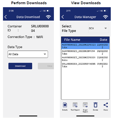
ContainerLINK will also display real time data from the unit in the app when a connection is established. The following components and details can be monitored, see Figure 4.14:
•System status including: control mode, operating mode, box temperature, and alarms.
•System values including: sensors, switches, outputs and miscellaneous items.
Figure 4.14 ContainerLINK - View Real Time Data
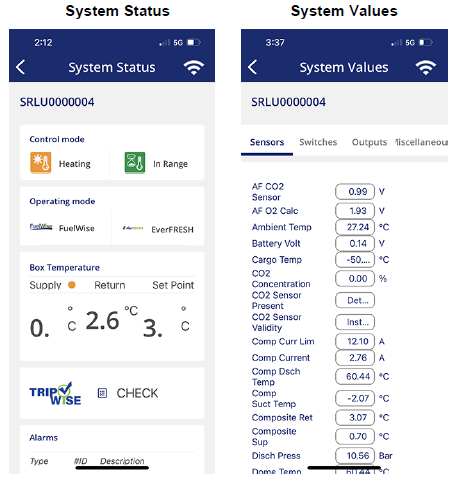
4.6.2.1 Obtaining Container Unit ID and Wireless Password
This procedure explains how to use the unit display to determine the container unit ID and wifi password. These are needed to connect to the ContainerLINK™ app.
Procedure:
1.Determine the container ID of the unit. This is an 11 character ID and is typically stamped on the container frame. To look up the ID on the unit display continue with the steps below.
a.Press the CODE SELECT key.
b.Use the Arrow keys to navigate to Cd40, then press ENTER. The last 7 characters of the ID are displayed.
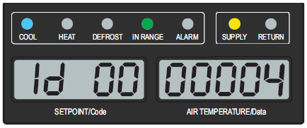
2.On the display, look up the six character wireless password. The password changes every four hours.
a.Press the ALT MODE key.
b.Use the Arrow keys to display "nEt", then press ENTER.
c.Use the Arrow keys to display "PASSW EntR", then press ENTER.
d.The display will show a 6 character password required to connect to this unit’s controller. Write down or take a picture of the password. The password is not case sensitive, so upper or lower case is not relevant.
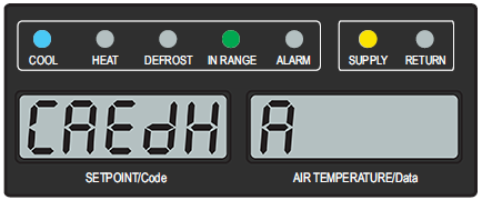
4.6.2.2 Connecting a Phone with ContainerLINK to a Unit
This procedure explains how to enter wifi settings for a particular container unit into the ContainerLINK app to establish a connection to the unit.
1.Open the ContainerLINK™ app and navigate to the Container screen, then the Wi-Fi Settings screen.
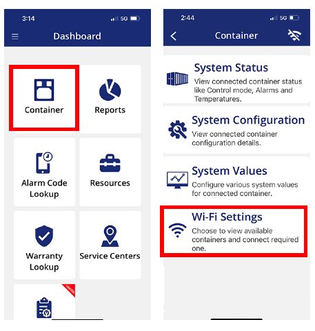
2.Depending on the mobile device, all available networks (along with Container IDs) within range may appear. Choose a Container ID to connect to. See Section 4.6.2.1 for obtaining Container ID.
On some mobile devices, this screen is bypassed and the Login screen appears directly.
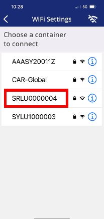
3.At the Login screen, enter or verify the Container ID and Password and select Connect. The values may be inputted automatically. If not, input the values without using any spaces. The password is not case sensitive, so upper or lower case is not relevant. See Section 4.6.2.1 for obtaining a password.
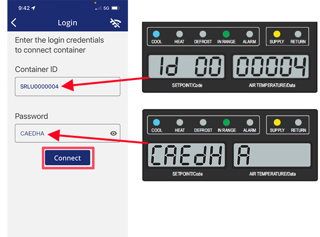
4.If a prompt asks to Join the network, select Join. After clicking Connect, a message will appear “Connected to the WIFI Successfully”. Click OK to begin using the connected features of ContainerLINK™.
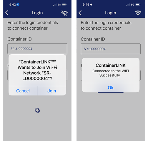
4.6.2.3 Connecting a Laptop with ContainerLINK to a Unit
This procedure explains how to enter wifi settings for a particular container unit into the ContainerLINK app to establish a connection to the unit.
1.Open the ContainerLINK™ app, navigate to the Settings page and select “WiFi” in the upper left corner.
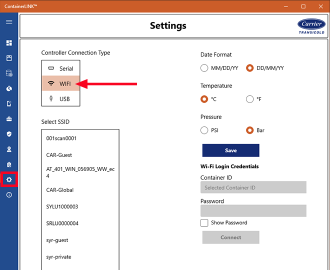
2.Choose the container unit to connect from the Select SSID box. After selecting, the ID is filled into the Container ID box on the right. Type in the password and click Connect. See Section 4.6.2.1 for container ID and password information.
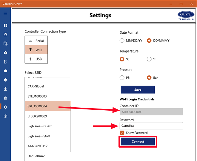
3.Wait for the confirmation message that connection was successful.

4.At the Container screens (System Status, System Configuration, System Values, Probe Calibration), the connected container ID will appear under the page title.
4.6.3Optional Interrogator Ports Connection
For units with ML5 controller, an optional front and rear interrogation receptacle are available. The front receptacle, mounted under the control box is for connectivity to third party devices. The rear receptacle, located inside the unit along side the USDA receptacles, is for USDA probe calibration only. There are no write commands capable from this port other than those related to USDA calibration.
4.7DataCORDER
Carrier Transicold “DataCORDER” software is integrated into the controller and serves to eliminate the temperature recorder and paper chart. DataCORDER Software is subdivided into operational software, configuration software, and data memory. DataCORDER functions may be accessed by keypad selections and viewed on the display module. For a description of DataCORDER communications, see Section 4.7.6.
The DataCORDER consists of the following components:
•Configuration software
•Operational software
•Data storage memory
•Real time clock (with internal battery backup)
•Six thermistor inputs
•Interrogation connections
•Power supply (battery pack)
The DataCORDER performs the following functions:
•Logs configured sensor data at the configured time interval.
•Records alarm activity.
•Records PTI results.
•Records modifications to the controller (i.e. configuration, time, software upgrade, etc).
•Records operational events (i.e. defrost, dehumidification, setpoint change, power On/Off, cooling mode, etc).
•Records optional events (i.e. USDA activity, trip start, probe calibration, GDP calibration, XtendFresh operation, vent position sensor location, etc).
4.7.2DataCORDER Configuration Software
The configuration software controls the recording and alarm functions of the DataCORDER. Reprogramming to the factory-installed configuration is achieved via the USB menu with a flash drive installed. An ML5 software file or a compatible configuration database file must be on the USB flash drive in order to gain access to the menu.
Procedure to Display DataCORDER Configuration Variables:
1.Press the ALT MODE key on the keypad.
2.Use the Arrow keys until “dCF” is displayed, then press the ENTER key.
3.Press an Arrow key until the left window displays the desired variable number. The right window will display the value of this item for five seconds before returning to the normal display mode. If a longer display time is desired, press the ENTER key to extend the display time to 30 seconds.
A list of the configuration variables is provided in Table 4–6. Descriptions of DataCORDER operation for each variable setting are provided in the following paragraphs.
Table 4–6 DataCORDER Configuration Variables
|
Title |
Default |
Option |
|
|---|---|---|---|
|
dCF01 |
(Future Use) |
-- |
-- |
|
dCF02 |
Sensor Configuration |
2 |
2, 5, 6, 9, 54, 64, 94 |
|
dCF03 |
Logging Interval (Minutes) |
60 |
15, 30, 60, 120 |
|
dCF04 |
Thermistor Format |
Short |
Long |
|
dCF05 |
Thermistor Sampling Type |
A |
A, b, C |
|
dCF06 |
Controlled Atmosphere / Humidity Sampling Type |
A |
A, b |
|
dCF07 |
Alarm Configuration USDA Sensor 1 |
A |
Auto, On, Off |
|
dCF08 |
Alarm Configuration USDA Sensor 2 |
A |
Auto, On, Off |
|
dCF09 |
Alarm Configuration USDA Sensor 3 |
A |
Auto, On, Off |
|
dCF10 |
Alarm Configuration Cargo Sensor |
A |
Auto, On, Off |
Two modes of operation may be configured, the Standard Mode and the Generic Mode.
In the Standard Mode, the user may configure the DataCORDER to record data using one of seven standard configurations. The seven standard configuration variables, with their descriptions, are listed in Table 4–7.
The inputs of the six thermistors (supply, return, USDA #1, USDA #2, USDA #3 and cargo probe) and the humidity sensor input will be generated by the DataCORDER.
Table 4–7 DataCORDER Sensor Configurations
|
Description |
|
|---|---|
|
2 sensors (dCF02=2) |
2 thermistor inputs (supply & return) |
|
5 sensors (dCF02=5) |
2 thermistor inputs (supply & return) 3 USDA thermistor inputs |
|
6 sensors (dCF02=6) |
2 thermistor inputs (supply & return) 3 USDA thermistor inputs 1 humidity input |
|
6 sensors (dCF02=54) |
2 thermistor inputs (supply & return) 3 USDA thermistor inputs 1 cargo probe (thermistor input) |
|
7 sensors (dCF02=64) |
2 thermistor inputs (supply & return) 3 USDA thermistor inputs 1 humidity input 1 cargo probe (thermistor input) |
|
9 sensors (dCF02=9) |
Not Applicable |
The Generic Mode allows user selection of up to eight network data points to be recorded. Changing the configuration to generic and selecting which data points to record may be done using the Carrier Transicold Data Retrieval Program. A list of the data points available for recording follows.
1.Control mode
2.Control temperature
3.Frequency
4.Humidity
5.Phase A current
6.Phase B current
7.Phase C current
8.Main voltage
9.Evaporator expansion valve percentage
10.Discrete outputs (Bit mapped - require special handling if used)
11.Discrete inputs (Bit mapped - require special handling if used)
12.Ambient Temperature Sensor (AMBS)
13.Evaporator Temperature Sensor (ETS)
14.Compressor Discharge Temperature Sensor (CPDS)
15.Return Temperature Sensor (RTS)
16.Supply Temperature Sensor (STS)
17.Defrost Temperature Sensor (DTS)
18.Discharge Pressure Transducer (DPT)
19.Suction Pressure Transducer (SPT)
20.Evaporator Pressure Transducer (EPT)
21.Vent Position Sensor (VPS)
The user may select four different time intervals between data recordings. Data is logged at exact intervals in accordance with the real time clock. The clock is factory set at Greenwich Mean Time (GMT).
The user may configure the format in which the thermistor readings are recorded. The short resolution is a 1 byte format and the long resolution is a 2 byte format. The short requires less memory and records temperature with variable resolutions depending on temperature range. The long records temperature in 0.01°C (0.02°F) steps for the entire range.
Three types of data sampling are available: average, snapshot and USDA. When configured to average, the average of readings taken every minute over the recording period is recorded. When configured to snapshot, the sensor reading at the log interval time is recorded. When USDA is configured, supply and return temperature readings are averaged and the three USDA probe readings are snapshot.
Alarm Configuration (dCF07 - dCF10)
USDA and cargo probe alarms may be configured to OFF, ON or AUTO.
If a probe alarm is configured to OFF, the alarm for this probe is always disabled.
If a probe alarm is configured to ON, the associated alarm is always enabled.
If the probes are configured to AUTO, they act as a group. This function is designed to assist users who keep the DataCORDER configured for USDA recording, but do not install the probes for every trip. If all the probes are disconnected, no alarms are activated. As soon as one of the probes is installed, all of the alarms are enabled and the remaining probes that are not installed will give active alarm indications.
Stored Temperature Display (Scrollback)
The DataCORDER records temperatures from the supply sensor, return sensor, P1, P2, P3 and C4 cargo sensors. The temperatures are recorded every hour.
Procedure to Display Stored Temperatures:
1.Press the ALT MODE key on the keypad.
2.Use the Arrow keys until “dCdSP” is displayed, then press the ENTER key.
3.Use the Arrow keys to toggle through S (supply), R (Return), P1, P2, P3 and C4 (Cargo) sensors.
4.Press the ENTER key and a temperature value will appear in the right window and 1 (with sensor designation) will appear in the left window to signify the temperature displayed is the most recent reading. Each press of the down Arrow key displays the temperature one hour earlier.
5.Press the ENTER key to alternate between sensors and times / temperatures. And use Arrow keys for scrolling.
4.7.3DataCORDER Operational Software
The operational software reads and interprets inputs for use by the configuration software. The inputs are labeled function codes. The DataCORDER function code assignments, see Section 4.7.4, may be accessed by the operator to examine the current input data or stored data.
Procedure to Display DataCORDER Function Codes:
1.Press the ALT MODE key on the keypad.
2.Use the Arrow keys until “dC” is displayed, then press the ENTER key.
3.Press an Arrow key until the left window displays the desired function code number. The right window will display the value of this item for five seconds before returning to the normal display mode. If a longer display time is desired, press the ENTER key to extend the display time to 30 seconds.
4.If a function is not applicable for the unit, dashes “-----” are shown on the display.
4.7.4DataCORDER Function Codes
dC1 Recorder Supply Temperature
Current reading of the supply recorder sensor (SRS).
dC2 Recorder Return Temperature
Current reading of the return recorder sensor (RRS).
dC3-5 USDA 1,2,3 Temperatures
Current readings of the three USDA probes.
dC6-13 Network Data Points 1-8
Current values of the network data points (as configured). Data point 1 (Code 6) is generally the humidity sensor and its value is obtained from the controller once every minute.
dC14 Cargo Probe 4 Temperature
Current reading of the cargo probe (#4).
dC15 Future Expansion
These codes are for future expansion, and are not in use at this time.
dC16 GDP Last Supply Sensors Calibration Date
The most recent date of GDP calibration of the supply sensors (STS / SRS) is displayed.
dC17 GDP Last Return Sensors Calibration Date
The most recent date of GDP calibration of the return sensors (RTS / RRS) is displayed.
dC18 GDP Supply Temperature Sensor Calibration Offset
The most recent calibration offset value of the supply temperature sensor (STS) is displayed.
dC19 GDP Return Temperature Sensor Calibration Offset
The most recent calibration offset value of the return temperature sensor (RTS) is displayed.
dC20-24 Temperature Sensors 1-5 Calibration
Current calibration offset values for each of the five probes: supply, return, USDA #1, #2, and #3. These values are entered via the interrogation program.
dC25 Future Expansion
This code is for future expansion, and is not in use at this time.
dC65 Future Expansion
This code is for future expansion, and is not in use at this time.
dC27 Future Expansion
This code is for future expansion, and is not in use at this time.
dC28 Minimum Days Left
An approximation of the number of logging days remaining until the DataCORDER starts to overwrite the existing data.
dC29 Days Stored
Number of days of data that are currently stored in the DataCORDER.
dC30 Date of Last Trip Start
The date when a Trip Start was initiated by the user. In addition, if the system goes without power for seven continuous days or longer, a trip start will automatically be generated on the next AC power up. Press and hold the ENTER key for five seconds to initiate a “Trip Start”.
dC31 Battery Test Results
Shows the current status of the optional battery pack.
PASS: Battery pack is fully charged. FAIL: Battery pack voltage is low
dC32 Time: Hour, Minute
Current time on the real time clock (RTC) in the DataCORDER.
dC33 Date: Month, Day
Current date (month and day) on the RTC in the DataCORDER.
dC34 Date: Year
Current year on the RTC in the DataCORDER.
dC35 Cargo Probe 4 Calibration
Current calibration value for the cargo probe. This value is an input via the interrogation program.
The DataCORDER may be powered up in any one of the following methods:
1.Normal AC power: The DataCORDER is powered up when the unit is turned on via the Stop-Start switch.
2.Controller DC battery pack power: If a battery pack is installed, the DataCORDER will power up for communication when the user presses the battery key.
3.Real Time Clock demand: If the controller is equipped with a charged battery pack and AC power is not present, the DataCORDER will power up when the real time clock indicates that a data recording should take place. When the DataCORDER is finished recording, it will power down.
During DataCORDER power-up, while using battery-pack power, the controller will perform a hardware voltage check on the battery. If the hardware check passes, the controller will energize and perform a software battery voltage check before DataCORDER logging. If either test fails, the real time clock battery power-up will be disabled until the next AC power cycle. Also, DataCORDER temperature logging will be prohibited until that time.
An alarm will be generated when the battery voltage transitions from good to bad indicating that the battery pack needs recharging. If the alarm condition persists for more than 24 hours on continuous AC power, it indicates that the battery pack needs replacement.
4.7.6DataCORDER Communications
Data can be retrieved from the DataCORDER and viewed with DataLINE software for Windows or the ContainerLINK™ app, see Figure 4.12. These programs allow interrogation, configuration variable assignment, screen view of the data, hard copy report generation, cold treatment probe calibration and file management. After software revision 6315, DataLINE 3.12 or ContainerLINK™ 2.2 or greater are required.
The ML5 controller allows this data retrieval via wired or wireless communications. See Section 4.6 for a description of ML5 communications. When connecting hard-wired with a cable, DataLINE software or ContainerLINK™ can be used. When connecting wirelessly with a phone or tablet, ContainerLINK™ must be used.
Procedures and information related to DataLINE software and its interface with the DataCORDER can be found in the 62-10629 DataLINE User Manual, located in the Literature section of the Container Refrigeration website. To find the manual from the Literature section, select Data Tools > DataLINE > All Documents.
The DataCORDER will record the initiation of a pre-trip test, see Section 4.5, and the results of each test included in pre-trip. The data is time-stamped and may be extracted via the Data Retrieval program. See Table 4–8 for a description of the data stored in the DataCORDER for each corresponding pre-trip test.
Table 4–8 DataCORDER Pre-Trip Result Records
|
Title |
Data |
|
|---|---|---|
|
1-0 |
Heater On |
Pass / Fail / Skip Result, Change in current for Phase A, B and C |
|
1-1 |
Heater Off |
Pass / Fail / Skip Result, Change in currents for Phase A, B and C |
|
2-0 |
Condenser Fan On |
Pass / Fail / Skip Result, Water pressure switch (WPS) - Open / Closed, Change in currents for Phase A, B and C |
|
2-1 |
Condenser Fan Off |
Pass / Fail / Skip Result, Change in currents for Phase A, B and C |
|
3-0 |
Low Speed Evaporator Fan On |
Pass / Fail / Skip Result, Change in currents for Phase A, B and C |
|
3-1 |
Low Speed Evaporator Fan Off |
Pass / Fail / Skip Result, Change in currents for Phase A, B and C |
|
4-0 |
High Speed Evaporator Fan On |
Pass / Fail / Skip Result, Change in currents for Phase A, B and C |
|
4-1 |
High Speed Evaporator Fan Off |
Pass / Fail / Skip Result, Change in currents for Phase A, B and C |
|
5-0 |
Supply / Return Probe Test |
Pass / Fail / Skip Result, STS, RTS, SRS and RRS |
|
5-1 |
Secondary Supply Probe (SRS) Test |
Pass / Fail / Skip |
|
5-2 |
Secondary Return Probe (RRS) Test |
Pass / Fail / Skip |
|
5-3 |
Evaporator Fan Direction Test |
Pass / Fail / Skip |
|
5-7 |
Primary vs. Secondary Evaporator Temperature Sensor Test |
Pass / Fail / Skip |
|
5-8 |
Future Expansion |
“-----” |
|
5-9 |
Primary vs. Secondary Evaporator Pressure Transducer Test |
Pass / Fail / Skip |
|
5-10 |
Humidity Sensor Controller Configuration Verification Test |
Pass / Fail / Skip |
|
5-11 |
Humidity Sensor Installation Verification Test |
Pass / Fail / Skip |
|
5-12 |
Humidity Sensor Range Check Test |
Pass / Fail / Skip |
|
6-0 |
Discharge Thermistor Test |
Pass / Fail / Skip |
|
6-1 |
Suction Thermistor Test |
Pass / Fail / Skip |
|
6-2 |
Discharge Pressure Transducer Test |
Pass / Fail / Skip |
|
6-3 |
Suction Pressure Transducer Test |
Pass / Fail / Skip |
|
6-4 |
Compressor Current Draw Test |
Pass / Fail / Skip |
|
6-5 |
Compressor Leak Test |
Pass / Fail / Skip |
|
6-6 |
Economizer Valve Test |
Pass / Fail / Skip |
|
6-7 |
Digital Unloader Valve Test |
Pass / Fail / Skip |
|
6-9 |
Liquid Injection Valve Test (If equipped) |
Pass / Fail / Skip |
|
6-10 |
Electronic Expansion Valve Test |
Pass / Fail / Skip |
|
7-0 |
High Pressure Switch Closed |
Pass / Fail / Skip Result, AMBS, DPT or CPT (if equipped) Input values that component opens |
|
7-1 |
High Pressure Switch Open |
Pass / Fail / Skip Result, STS, DPT or CPT (if equipped) Input values that component closes |
|
8-0 |
Perishable Mode Heat Test |
Pass / Fail / Skip Result, STS, time it takes to heat to 16°C (60°F) |
|
8-1 |
Perishable Mode Pulldown Test |
Pass / Fail / Skip Result, STS, time it takes to pull down to 0°C (32°F) |
|
8-2 |
Perishable Mode Maintain Test |
Pass / Fail / Skip Result, Averaged DataCORDER supply temperature (SRS) over last recording interval. |
|
9-0 |
Defrost Test |
Pass / Fail / Skip Result, DTS reading at end of test, line voltage, line frequency, time in defrost. |
|
10-0 |
Frozen Mode Heat Test |
Pass / Fail / Skip Result, STS, time unit is in heat. |
|
10-1 |
Frozen Mode Pulldown Test |
Pass / Fail / Skip Result, STS, time to pull down unit to -17.8°C (0°F). |
|
10-2 |
Frozen Mode Maintain Test |
Pass / Fail / Skip Result, Averaged DataCORDER return temperature (RRS) over last recording interval. |