Section 5
Alarm display is an independent controller software function. If an operating parameter is outside of the expected range or a component does not return a valid signal back to the controller, an alarm is generated. The XtendFRESHTM Controlled Atmosphere option alarms are AL07, AL09, AL10, AL29, AL62 and AL96.
AL07 |
Fresh Air Vent OPen |
|
|---|---|---|
Cause: |
For units equipped with XtendFRESH and a Vent Position Sensor, the controller will monitor the manual fresh air opening at a pre-determined time. If during this time the fresh air vent is open and XtendFRESH is active, an alarm will be generated. If alarm is active, the controller monitors the manual fresh air once per hour. Upon clearing the alarm, the controller goes back to monitoring at the pre-determined time. |
|
|
Component |
|
|
Troubleshooting |
Manually reposition vent to 0% and confirm using Cd45. If Cd45 is not reading 0%, perform a calibration of the panel. Refer to Section 6.9. If unable to obtain a zero reading, replace the defective VPS. If unit is loaded, ensure vent is closed. Note and replace VPS on next PTI. The alarm will not affect the XtendFRESH system from operating. |
O2 SENSOR FAILURE |
||
|---|---|---|
Cause: |
Triggered anytime the O2 sensor reading is outside of the normal operation range, after an initial signal was detected. |
|
|
Component |
|
|
Troubleshooting |
Check Cd44 and scroll down to 02V. The O2 sensor output will be displayed in millivolts (130mV to 4100mV). Switch equipped: If voltage is not present at Cd44 and a sensor switch module is installed, check for O2 voltage on the black wire connected to the sensor switch module, connecting ground of meter to TP9. If the voltage is in the 130mV to 4.1V range, directly wire the black wire to KD04. This may cause an AL07 depending on O2 reading but XtendFRESH will operate normally. If no voltage on the black wire, proceed to next step. Check wiring (refer to schematic), and correct if found mis-wired. If O2 sensor is available, remove the upper fresh air panel and evaporator motor and replace the sensor. If after replacing sensor AL09 continues, replace amplifier. If parts are not available, turn XtendFRESH option off (Cd43) and open the Manual Fresh Air Vent. |
AL10 |
CO2 SENSOR FAILURE |
|
|---|---|---|
Cause: |
Triggered anytime the CO2 sensor reading is outside of the normal operation range, after an initial signal was detected. |
|
|
Component |
|
|
Troubleshooting |
Check the voltage at MC5 to the ground pin on TP9. (1 - 4.7 vdc) Check wiring (refer to schematic), and correct if found mis-wired. If part is available, remove upper fresh air panel and evaporator motor; replace sensor. If no part is available, take no action and service at next PTI. XtendFRESH will continuously run the scrubber. O2 level will be controlled with the opening and closing of the fresh air vents as required. |
AL29 |
Loss of Atmospheric Control |
|
|---|---|---|
Cause: |
Triggered whenever the CO2 level is above its upper limit by 1% for 60 minutes. Or, when the O2 level is greater than 1% below its setpoint for longer than 30 minutes after the unit has been in range. The alarm is triggered off when the levels return to within the normal range. |
|
|
Setup |
Run Cd43 test mode for troubleshooting the below components. At the end of test mode, a sensor calibration will be attempted. Under loaded box conditions, the sensor values may post “No Cal” or “CAL FAIL”. Results from original calibration will be retained. If test mode times out, then hold the code select key for 3 seconds to exit test mode. |
|
Troubleshooting |
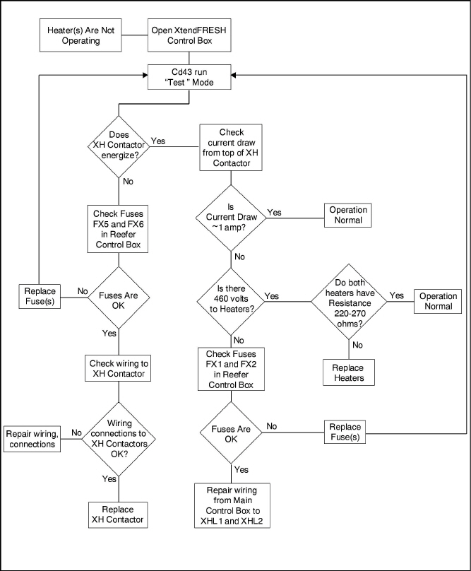
If components do not energize, check FX1 and FX2 for power (460 VAC). If fuse is open, check heater continuity (XHT1 to ground). Must be greater than 1 mega ohm. If less than 1, disconnect the heater at XHT1 and XHT2. Replace fuse. Unit will control on fresh air solenoids. |
|
Component |
|
|
Troubleshooting |
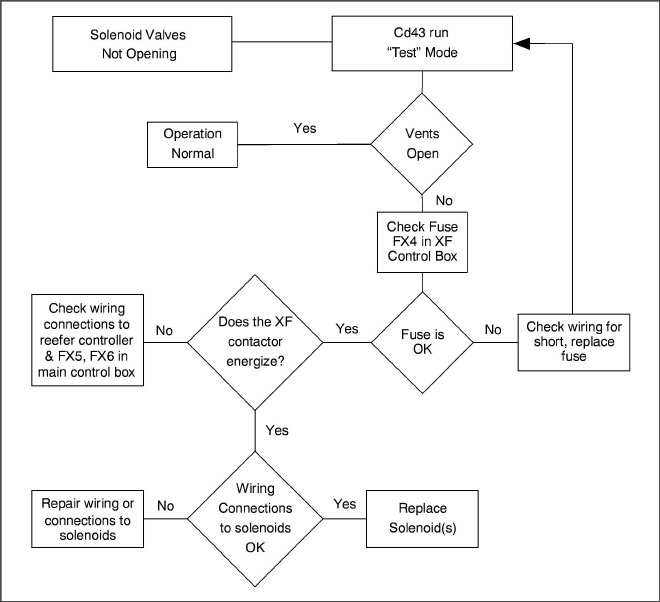
Visually inspect to see if the Solenoid Valves are opening air vents. If vents open, troubleshoot the next component. If vents do not open, continue with troubleshooting below. Check FX4 fuse for power (~20 volts dc). If fuse is open, check wiring and or replace solenoid if part is available. If no part is available, open manual fresh air vent. |
|
Component |
|
|
Troubleshooting |
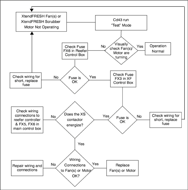
Visually inspect to see if the XtendFRESH Fan(s) are running (air blowing on left, intake on right), check current draw of motor at the XST1 (~40 to 200 milliamps / contactor load side). Troubleshoot the non-operating component. If both are running, proceed to next component. Verify XS contactor is pulling in. If not, check FX6 fuse for power (24 VAC). If not, check power at controller KB4. Check FX3 fuse for power (~20 vdc). If no power, replace fuse. If fuse opens a second time, take no further action. O2 level will be controlled with the opening and closing of the fresh air vents. If part is available, replace either fan or scrubber motor. Fan is replaceable from the front on a loaded unit; Scrubber motor is not. If no part is available or accessible, take no action and service at next PTI. O2 level will be controlled with the opening and closing of the fresh air vents. |
|
Component |
|
|
Troubleshooting |
Verify XH contactor is pulling in. If not, check FX6 for power (24 VAC). If open ohm contactors XHA1 and XSA1 to ground. Replace (12 Amp) contactor. If contactor is pulling, power unit off and check heater resistance from XH1 to XH2 (450 to 500 ohms). If heater is outside of the range, disconnect heater at XHT1 and XHT2 and replace at next PTI. Unit will control on fresh air solenoids. |
AL62 |
O2 Out of Range |
|
|---|---|---|
Cause: |
This is a notification alarm and does not pose a risk to fresh produce. AL62 is triggered when there is an indication that the O2 level is rising after reaching its setpoint (+ 1%). If O2 level exceeds 4% above setpoint, the alarm is activated. The alarm does not activate if the unit was pre-tripped or trip started between last reaching its O2 setpoint and exceeding the plus 4%, or if power has been turned off for eight hours. The alarm is deactivated if O2 drops below setpoint (+ 1%) or if a pre-trip or trip start is performed. |
|
|
Component |
|
|
Troubleshooting |
Refer to the troubleshooting of the Scrubber Motor in the AL29 alarm. |
|
Component |
XtendFRESH Solenoid Valves |
|
Troubleshooting |
Refer to the troubleshooting of the Solenoid Air Vent in the AL29 alarm. |
|
Component |
Container Air Tightness |
|
Troubleshooting |
Seal container where possible (access panels, rear doors, mounting hardware, etc). |
SCRUBBER ROTATIONAL FAILURE - optional feature |
||
|---|---|---|
Cause: |
Feedback from the Scrubber Motor to the controller is not sensed when the motor is turning. |
|
|
Component |
|
|
Troubleshooting |
Check to see if Fuse FX6 is blown. Replace Fuse if necessary. |
|
Component |
|
|
Troubleshooting |
Run Test Mode and verify scrubber bed is turning. If back panel cannot be removed to check, verify the scrubber amperage consumption, read at XS contactor wire XSL1. If between 40 and 200mA, motor is rotating properly. If no current detected, check and replace FX3. If current spiking to 350mA for 2 seconds then dropping to 90mA, the scrubber motor is locked. If the scrubber motor is locked, further inspection of the scrubber bed is required. Unit will control CO2 with the fresh air solenoid when this alarm occurs if scrubber inaccessible. If Scrubber Motor not operating, follow the troubleshooting flowchart in Section 5.2.2 and take appropriate action. |
|
Component |
|
|
Troubleshooting |
Once it has been verified that the scrubber motor is rotating check the wiring connections to the GIM module. If all wires are secured properly, re-place the GIM module if one is available. If not, the unit will control CO2 using the fresh air solenoids. |
5.2XtendFRESH Assembly Not Operating
5.2.1Solenoid Valves Not Opening Air Vent(s)
5.2.2XtendFRESH Fan(s)/XtendFRESH Scrubber Not Operating