November 2019 Issue
Inside This Issue:
Micro-Link® 5 Controller
Carrier Transicold recently released a new generation controller option called the MicroLink® 5 (ML5) controller (part # 12-55015). The ML5 option is available on the 69NT40-571-XXX PrimeLINE®, 69NT40-575-XXX PrimeLINE ONE®, and is supported by the T-372 manual. The PrimeLINE units will be supported by 63XX.ml5 software with future implementation on the NaturaLINE® units.
The ML5 offers many new capabilities including Micro USB Type-B connection for easier software upload / downloads, wireless connectivity allowing for a more efficient communication interface, more controller Inputs and Outputs for expanded capabilities, faster processor and larger storage capacity for more efficient control algorithms and data storage and smart battery technology to ensure the backup capabilities are available when required on critical cargoes.
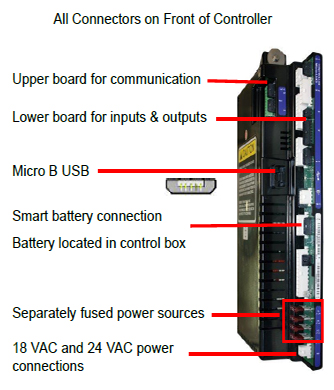
The controller was designed with considerations made for better serviceability. The ML5 controller has all the connectors on the front of the controller. Internally, more sensing capabilities were integrated to allow for the controller to perform a self-diagnostic test. Entering Cd70 and pressing test mode will perform an internal test, validating if the controller is not functioning properly prior to changing it out.
Other enhancements made for serviceability include new 3 digit alarms. Alarms are distinguished by the first digit. Alarms starting with a ‘0’ are critical refrigeration alarms. For example, AL003 Loss of Superheat Control. The second two digits on all alarms will remain the same as current two digit alarm codes. AL003 on ML5 is the same as AL03 on the ML3. 2XX alarms are non-critical refrigeration alarms, and 9XX are controlled atmosphere (CA) critical and non-critical alarms. Both ML3 and ML5 alarms are included in the Alarm Code Lookup in the ContainerLINK™ app.
As the ML5 is a new controller with enhanced capabilities, new system harness, and advanced layout, it is not backwards retrofitable with the ML3 controllers.
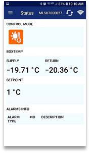
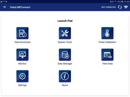
The ML5 wireless capabilities allow for quick connection to the new DataLINE Connect™ app. The DataLINE Connect app puts users in control with an interface that provides reefer container monitoring and management capabilities from a smart phone or tablet.
- Determine the operational state of reefer containers.
- Monitor unit data via the app’s interface.
- Operate on multiple mobile devices.
- Interrogate the controller.
Phone App
As part of the XtendFRESH® (XF) option, a purge mode was added with software version 5372. The purge mode is used for cargoes that cannot reach the target atmosphere by normal respiration. Instead, external gas is used to purge the container after stuffing to reach the target set point before the trip. The purpose of this mode is to prevent nuisance alarms and premature venting or scrubbing while the gas is being injected.
Function Code 43 will now provide 4 modes of operation: Fresh, Test, OFF, and Purge. The Purge mode suspends XF control and alarm actions, while the customer purges the container to the desired gas concentration. When activated, Purge mode stays active for a set period of time, then goes into normal XF mode.

When Purge mode is selected, the CO2 and O2 setpoints are entered exactly the same way as in “FrESH” mode. After entering the CO2 and O2 set points, “PUrgE” is displayed on the left and the option of ON or OFF is displayed on the right. Purge mode is activated by selecting ON and then setting a timer. If OFF is selected, Purge mode is either not activated or terminated if Purge mode was previously activated. Once Purge mode has been activated, all XF control actions and alarms 29 and 96 are suspended for the time selected of 1 to 10 hrs in 1 hour intervals (5 hour default).
During Purge mode, while timer is counting down, the display toggles at 5 second intervals: Left /Setpoint, Right / Temperature, followed by Left / “Purge”, Right / Timer Countdown in 0.1 increments (ex 5.0, 4.9, 4.8 etc).
When the timer expires, the display will revert to normal temperature control display with FrESH mode enabled. Purge mode is terminated on power cycle, trip start, defrost, or pretrip. Code 43 displays PURGE while the timer is counting down. When the timer expires, Cd 43 will display FrESH.
Submenu:
CO2 Setpoint: Display “CO2SP” on the left display and flash the current CO2 setpoint percentage value on the right display. The user presses the Arrow keys to select a value in the range from 0 - 19%. When the value is selected, the user presses Enter to set the value and go to the O2 setting.
O2 Setpoint: Display “O2 SP” on the left display and flash the current O2 setpoint percentage value on the right display. The user presses the Arrow keys to select a value in the range from 3 - 21%. When the value is selected, the user presses Enter to set the value and go to PURGE setting.
Purge displays “PUrgE” on left display. Flash the current state of Purge mode on right display “ON” or “OFF”. The user presses the Arrow keys to switch between states. When the state is selected, the user presses Enter to set the state. When “OFF” is selected, the unit will run the normal Fresh Mode with setpoints already entered.
When “ON” is selected, “tim” will display on the left and the current Purge time (5 hr. default) will display on the right. The user presses the Arrow keys to set a value from 1 - 10 hours to run “Purge”. When the value is selected, the user presses Enter to set the value, entering the Purge mode.
Gas Charging Procedure (N2 and CO2):
1.Open the manual fresh air vent to allow for charging of gas.
If unit is equipped with a Vent Position Sensor (VPS):
a.Bring up Cd43 on the display and set to Off mode to disable all XtendFRESH operations.
b.Bring up Cd45.
c.Open the manual fresh air vent until the display reads 10 CFM.
If unit is not equipped with a Vent Position Sensor (VPS):
a.Open the manual fresh air vent until the indicator points to approximately 9 CFM.
Do not inject gas into the container unless the manual fresh air vent is opened. Damage to the unit and risk of personal injury exists if a pressure relief pathway is not established.
2.Enable Purge mode using Cd43. This is done to establish the amount of time needed to purge O2 and CO2. Refer to Purge Mode procedure. If not using Purge mode, the CO2 and O2 levels can be viewed in Cd44.
3.Purge mode is now active.
4.To establish the proper level of O2 in the unit, charge with N2 gas. Connect the hose from the N2 regulator to the unit equipped gas injection port. Then, start releasing N2 gas until the O2 reaches the desired level.
If injection pressure is too high, then there is a risk of clearing the unit defrost condensate trap. If this happens, the trap will need to be refilled with water.
5.To establish the proper level of CO2 in the unit, charge with CO2 gas. Connect the purging hose to the CO2 regulator. After injection, the sensor may read much lower than target setpoint for at least 30 minutes.
Increasing the CO2 pressure too high will run the risk of freezing the regulator. Due to slow mixing and sensor reading lag, the CO2 level will continue to rise for some time even after stopping the CO2 injection.
6.Once the Purge mode timer is expired, remove the gas injection hose connections and close the manual fresh air vent. If gas concentrations reach desired levels prior to the timer expiring, set Purge mode in Cd43 to OFF prior to closing the manual fresh air vent. When the timer is expired or Purge mode is set to OFF to disable it, the unit will revert to Fresh mode using the setpoints entered for Purge mode.
NaturaLINE® Unit Low Refrigerant Check (R-744)
With software version 5708, a pre-trip test P6-10 was added to check for a low refrigerant charge.
This test is not for loaded or pre-cooled units. The test should be run when the box and ambient temperature are within range of each other.
Based on ambient condition, one of two methods will be used to check the charge:
- Standstill Pressure Check (Ambient Temperature > 35°C (95°F), initiated at the start of P6.
- Pulldown Charge Check (Ambient Temperature < 35°C (95°F), initiated after P6-9.
When the test is run, the controller will evaluate the following sensors in order to determine the refrigerant charge level in the unit:
- Ambient Temperature
- Supply Temperature
- Return Temperature
- Suction Pressure
- Flash Tank Pressure
- Discharge Pressure
If the calculation is within a set of validated values, a “PASS” will be posted in DataLINE at P6-10.
If pressures are below the values, all remaining tests will be skipped and report “FAIL”. Result will be posted in DataLINE at P6-10.
If the temperature or pressures are not in range for the test, a “Skip” with cause (delta P or T) will be posted in DataLINE at P6-10.
All reference to the DataLINE postings will be in DataLINE version 3.2 or later.
If refrigerant is added, R-744 with a purity level of 99.9% is required, per AHRI700.
Click here for AHRI 700 Standard
Refer to unit service manual or TechLINE article Volume 23 # 1 (July 2017 Issue) for charging procedures.
XtendFRESH Unit Alarm 96 Troubleshooting
As the Scrubber motor begins to rotate, the motor will send a pulse to the Ground Isolation Module (GIM). The GIM uses an optical sensor to detect the pulses and transmit a signal to the controller confirming scrubber rotation. A failure to sense rotation when scrubbing will result in an Alarm 96. This alarm is primarily the result of either a problem with the GIM module, scrubber motor, controller or fuse.
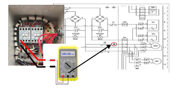
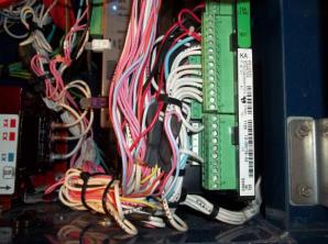
The first step would be to check if the scrubber motor is rotating. This check could be either a visual or electrical check. If the container is loaded, an electrical check can be made by checking the mA draw of the scrubber motor. To perform the electrical check, remove the XF control box panel and connect a DC amperage clamp meter on wire XST1 contactor wire.

Set the unit temperature selection to a perishable setpoint (above -10°C /14°F) and run the code select Cd43 “tESt” mode. This will ensure scrubber rotation is being called for.
Power the unit on and monitor current. If current is between 80 and 200 mA, the scrubber is rotating. Proceed to troubleshooting the GIM module.
If no current is present, check the FX3 fuse. If the fuse is good and current is still not present, the scrubber motor should be evaluated.
If the amperage spikes to ~360mA during the test, then this is an indication that the scrubber motor may be locking up. Further inspection of the scrubber bed assembly is required.
If a DC amp meter is not available a volt meter, capable of reading > 1A DC current set at the mA scale, can be used by disconnecting the XS1 wire from the contactor and routing it though the volt meter (in series) back to the XS1 contactor connection.
If the scrubber is rotating properly, the next step is to check the GIM module.
To check the GIM module, open the container control box and place your multi-meter, set on the DC voltage scale at controllers MC1 (positive) and MC8 (negative) leads.
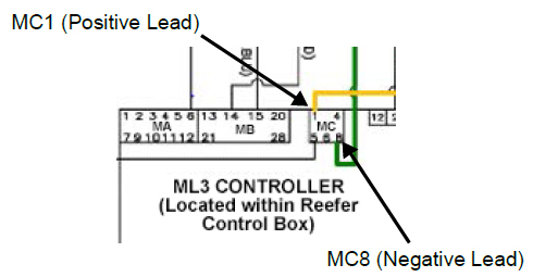
Power the Container unit on. The reading should be approximately 5.2 VDC.
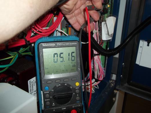
If 5.2 VDC is not present, check wiring between controller and the module, and retest.
If 5.2 VDC is still not present, the controller is suspect.
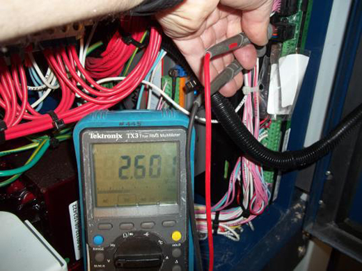
If the 5.2 VDC is present, monitor DC voltage when running in the XF “tESt” mode. When the scrubber turns on, the voltage should drop to approximately 2.6 volts DC.
If approximately 2.6 volts is present, the GIM module is working. End the test as the module is good.
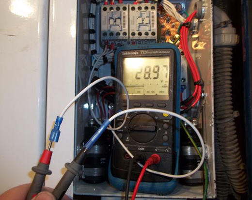
If voltage at MC1 does not change, verify the input voltage to the GIM module by opening the XF control box and checking voltage between XST1 (+) and XC1 (-). When scrubber is operating in “tESt” mode, the voltage should be between 17.2 VDC and 30 VDC.
If voltage is not present, repair power supply. If voltage is present, proceed to testing the scrubber motor output.
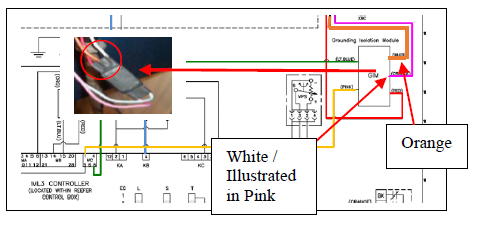
To test the scrubber motor output, you will need to splice into the GIM wire harness. The GIM module is located next to the ML3 controller in the refrigeration control box. The wiring harness has 5 wires, Light Blue, Pink, White, Orange, and Red.
Connect your meter, reading DC voltage with the ground lead on the white wire (shown in black) and positive lead on the orange wire.
Power up unit and run “tESt” mode. When scrubber is energized, you should read approximately 360 mVDC.
If approximately 360mV is not present, the signal from the scrubber motor is not being received. Check the wire from the scrubber to GIM module and scrubber motor. Repair or replace as required. If ~360mV is present and output voltage at MC1 does not drop to approximately 2.6 volts DC as per the previous check when the scrubber is running, the module should be replaced.
NaturaLINE® HPXV Coil Position
The NaturaLINE high pressure expansion valve regulates the pressure going into the flash tank. Over compression of the coil on the stem of the valve could result in the unit cycling on high pressure with the valve failing to correctly open.
If this occurs, one of the first steps to troubleshoot the unit is to check the positioning of the coil on the valve stem.
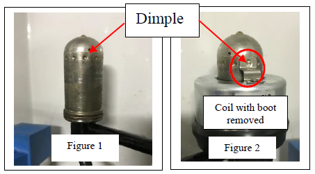
The coil sits in a dimple on the stem of the valve, as seen in Figure 1. In Figure 2, the boot of the coil was removed to show how the coil retainer pin engages the dimple on the valve stem. The removal of the boot in Figure 2 is shown for illustrative purpose only.
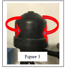
When installing the coil, push all the way in on the stem and then back out slightly until you feel and hear the click.
To ensure proper coil position, rotate the coil left and/or right ~1/8 turn to feel the click, as shown in Figure 3, when you are moving from dimple to dimple.
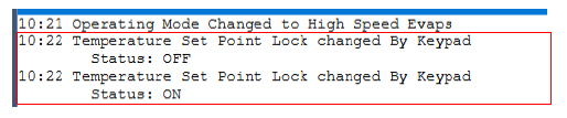
Temperature Setpoint Lock
With software version 5373 a temperature setpoint lock feature was added to the unit using a new code select “Cd70”.
This code select locks out the setpoint selection requiring the user to manually turn it off, prior to making a setpoint change. In doing this, it eliminates concern that the setpoint could be occidentally changed when scrolling through the code selects.
If the setpoint lock is “ON” and the user attempts to enter a new set point, they will see a message of “SPLK” (Setpoint Lock) in the left display and “ON” in the right for five seconds.
An event will be recorded in the DataCorder each time the action of either turning it “ON” or “OFF” is taken.
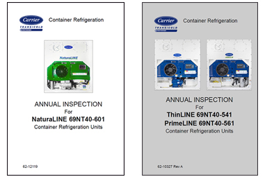
NaturaLINE Annual Inspection Guide
In ongoing support of the NaturaLINE unit an annual inspection guide was released (62-12119). This manual follows guidelines used in creating the annual inspection guide for the ThinLINE® and PrimeLINE® units (62-10327 Rev A).
These manuals can be found on the Carrier Transicold® Website.
Listed below is the website that can be checked for the upcoming hands on training schools along with a listing of the available On-Line courses.
Please note that all scheduled courses are subject to a minimum enrollment of 12 students. Register early to ensure schools are held.
![]()
Click here for course listing.
Listed are the software release versions for operating and working with Carrier Transicold units. Prior to upgrading software on units, you should seek agreement from the equipment owners.
Recip Unit (ML2/1207, ML2i / 5159, ML3, 5167)
Scroll Unit (ML2i, 5360 /ML3, 5373 / ML5, 6301)
NaturaLINE (ML3, 5708)
EverFRESH Controlled Atmosphere - 3115
DataLINE 3.4 / DataBANK 0513
Menu - 0116, Software cards with revision greater than 5159 or 5361 must have menu 0116, or an error could occur.
ContainerLINK Rev 1.2.0, Oct-22-2019
After completing a software upgrade, verify the user selections (i.e. defrost interval, set point, etc.).
TechLINE is a publication of Carrier Transicold © Carrier Corporation, Invalid field: Current Date (Short)
Editor: Perry Hoover
Contributors: Barry Hofsdal, David Whyte, Tom Graf, Matt Schlote, Nelson Morales
Thanks to all who supported this release.