Inside This Issue:
4 Tier Service Center Network
As an initiative to grow and build the Carrier® Transicold® Authorized Service Provider (ASP) network, we have implemented a 4 Tier service network consisting of:
•Premium Service Center
•Advanced Service Center
•Service Center
•Repair Center

Each of these service center classifications offers different levels of technical proficiency and parts support. With this information, the end customer will have a better understanding of what they can expect to see when using that service center location. To ensure the requirements for the levels are maintained, Carrier has implemented a service center audit procedure conducted by Carrier Transicold’s global service organization. To find a service center in your region of the world, go to the Carrier Container website.
Good Distribution Practice (GDP) Introduction
European Commission GDP (Good Distribution Practices) guidelines, which are used worldwide, call for the equipment used to control or monitor environments where medicinal products are stored or transported be calibrated in accordance with pharmaceutical shipper specifications, typically every six months or annually.
The capability to calibrate sensors in a Carrier container unit has been in place for the USDA sensors for some time. With software version 5368, we are now adding the ability to calibrate the supply and return air temperature sensors in the PrimeLINE® unit using DataLINE™ software version 3.1.
After loading 5368 into the unit, and upgrading your DateLINE™ software, follow detailed instruction for using GDP calibration in the operations & service manual.
DataLINE

Do not downgrade after loading as the calibration event will be lost.
1.From the DataLINE start screen, click on the Probe Calibration button.
2.From the Probe Calibration screen, click on Calibrate Supply Sensors or Calibrate Return Sensor button.
3.On the Service Center Location Pop- up, fill in the Service center name and location. This information will be recorded in the download.
4.If the reminder to check the ice bath temperature is at 0deg C appears, click OK to acknowledge.
5.Click Start Cal, and the calibration process will start. The process is automated and will take a minimum of 1 minute and a maximum of 5 minutes.
6.Once the process is complete, a calibration pop-up will appear. The results column will show if the calibration for the particular sensor passed or failed.
7.Calibration will fail if the temperature stability cannot be achieved (not more than 0.1°C fluctuation) or the sensor offset is greater than 0.3°C (0.5°F). Replace sensor and repeat calibration.
PrimeLINE Unit P6-5 Test
In conjunction with our December 2013 TechLINE article (pre-trip P6-5), Carrier Transicold has introduced the following procedures to assist the technician in troubleshooting a P6-5 occurrence.
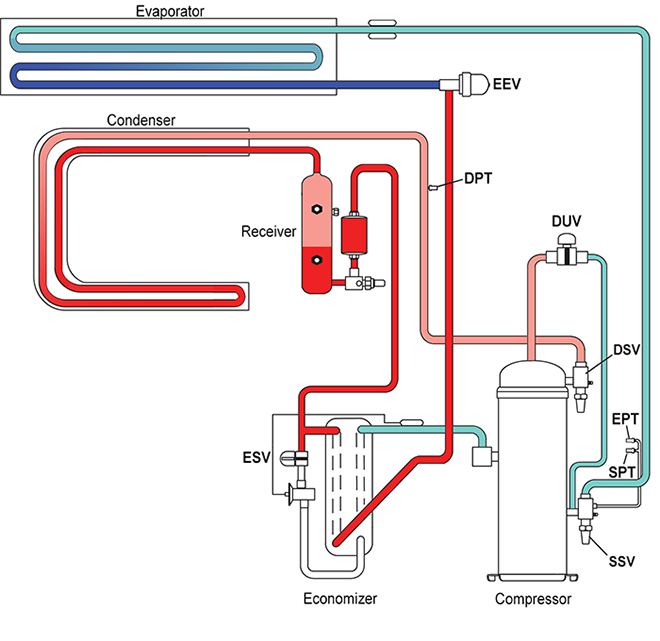
PrimeLINE® unit pre-trip P6-5 ensures that the compressor holds pressure internally, assuming the ESV (P6-6), DUV (P6-7) and EEV (P6-10) are working correctly. Due to the complexity of P6-5 testing, the best practice is to always use the latest version of software to ensure that the most up to date diagnostic is used.
At the start of pre-trip P6-5, the compressor will run to create a pressure differential between the suction and discharge of the compressor. On completion, the compressor is turned off. If the suction side pressure does not increase more than 8 psi, the test passes, otherwise, the test fails. If the test fails, the cause of the leakage needs to be determined.
The 8 psi rise in suction pressure may be attributed to high pressure returning back to the compressor through a leak at any of the following refrigeration circuits:
•Electronic Expansion Valve (EEV)
•Economizer Expansion Valve (ESV)
•Digital Unloader Valve (DUV)
•Pressure Transducer (DPT, SPT, EPT)
•Compressor
The following steps are recommended to assist the technician in this troubleshooting procedure:
1.Confirm the software revision by accessing Cd18. Confirm that software is revision 5365 (or greater). Seek agreement from the equipment owners if necessary. Otherwise, update software to latest version and run P6-5.
2.Test the Pressure Transducers (DPT, SPT, EPT).
a.Remove DPT, SPT and EPT from the refrigeration system.
b.Check DPT with Cd14. Check SPT and EPT with Cd12; Cd12 will display suction pressure in the right display. Pressing ENTER again will display evaporator pressure in the left display.
c.At sea level the disconnected DPT, SPT and EPT should all read zero. Above sea level all the transducers should be reading the same. Replace defective pressure transducers, if necessary.
3.Run a Pre-Trip P7. Press the PRE-TRIP key and use the arrow key to scroll to test P7 and press ENTER. The controller will initiate the high pressure test. If the compressor internal seals are leaking, it will fail P7.
4.Test the Electronic Expansion Valve (EEV).
a.Connect the manifold gauge set to the Discharge Service Valve (DSV) and Suction Service Valve (SSV), and mid-seat them.
b.Access Cd41.
c.Press “ENTER” key to select tIM, and set to 5 min, using the arrow keys.
d.Press “ENTER” key twice to select EEV and set to “0” using the arrow keys, then press “ENTER.”
e.Allow suction pressure to pull down to a vacuum, as shown on the manifold gauge set. Troubleshoot and replace defective EEV (valve and or coil) if necessary.
f.Perform a power cycle to reset Cd41 setting. Re-test EEV if necessary.
5.Test the Digital Unloader Valve (DUV).
a.Front seat the Liquid Line Service Valve and pump down the refrigerant. To perform an automatic pump down using Cd59 pump down logic, refer to Operations and Service manual (T-362) for more info.
b.Front seat the discharge and suction service valves to isolate the compressor.
c.Disconnect DUV from the top of compressor.
d.Install a ½ to ¼ inch flared adapter / O-ring (CTD# 40- 50076-00SV) to the DUV side.
e.Pressurize the line to 50 psi (3.5 bar) of nitrogen at the adapter connection, then close supply at the tank.
f.If pressure decreases at the tank regulator, the DUV is leaking and should be replaced.
g.If DUV is not leaking, energize DUV by removing coil and placing a magnet on the valve stem. This should open the valve. If the pressure does not decrease at the tank regulator, replace the valve as it did not open.
6.Test the Economizer Solenoid Valve (ESV).
a.If the DUV passes, remove the flare adapter / O-ring (CTD# 40-50076-00SV) from the DUV side, and reconnect the line to the top of the compressor.
b.Disconnect the economizer line from the compressor.
c.Connect a tank of dry nitrogen to the Liquid Line Service valve (it should already be front seated during the pump down procedure) and pressurize the system to 50 psig, then close the supply at the tank.
d.If pressure decreases at the tank regulator and nitrogen can be detected coming out of the economizer line, the ESV is leaking and should be replaced.
e.If ESV is not leaking, energize ESV by removing coil and placing a magnet on the valve stem. This should open the valve. If the pressure does not decrease at the tank regulator or you cannot feel or hear the nitrogen escaping through the disconnected economizer line, replace the ESV as it did not open.
Following these steps in checking the software, Pressure Transducers, EEV, DUV and ESV ensures all are working properly leaving the compressor as the root cause of the failure. Following is a quick P6-5 checklist for troubleshooting:
•Ensure software is revision 5365 (or greater). If not, update software to latest version and re-run P6-5.
•Disconnect the DPT, SPT and EPT and verify pressures. Replace defective pressure transducers if necessary.
•Perform P7 and make sure it passes P7 test.
•Perform EEV Test via Cd41, confirm suction pressure to pull down to a vacuum as shown on the manifold gauge set (Micron gauge).
•Perform DUV Test. Confirm DUV is not leaking, valve opening and closing.
•Perform ESV Test. Confirm ESV is not leaking, valve opening and closing.
•Ensure system pressures are correct after testing when using nitrogen for leak tests.
NaturaLINE Unit Evacuation and Charging Procedures
This article will review the service tasks of charging and evacuating the NaturaLINE® unit along with required tools.
Software Revision: 57XX
Controller: Green Label (12-55010)
Refrigerant: 10 lbs. (4.5 KG) / WO WCC
Service Tools:
•07-00527-00 Manifold Gauge Set
•14-00396-20 HPXV Magnet Tool
•07-00512-00 Solenoid Magnet Tool (x2)
•07-00529-00 CO2 Leak Detector
Setup:
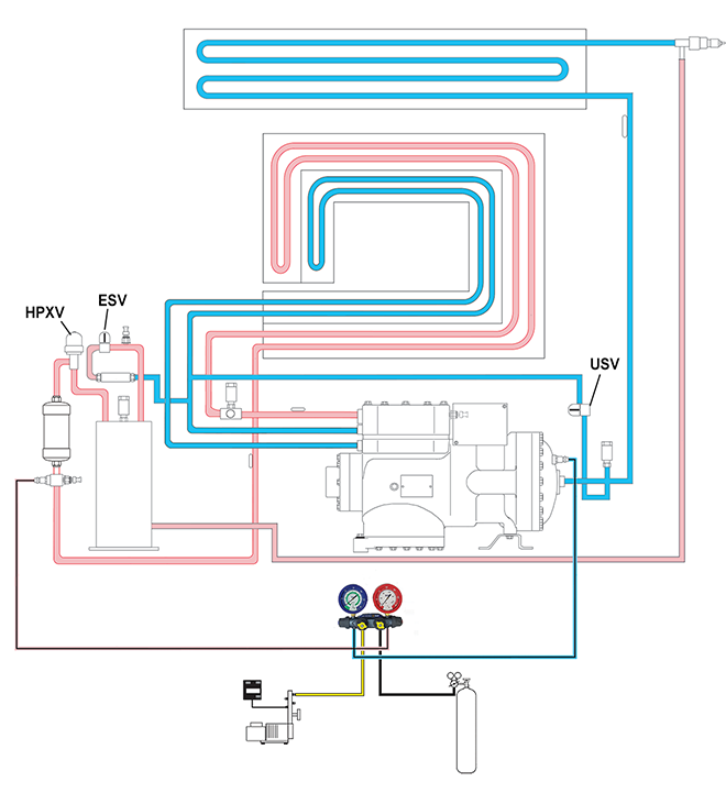
To evacuate and charge the system, the Economizer Solenoid Valve (ESV), Unloader Solenoid Valve (USV), and High Pressure Expansion Valve (HPXV) must be opened using the service magnet tools.
HPVX (Tool: 14-00396-20)
•Remove the power head from the expansion valve body.
•Place the magnet tool over the valve body and rotate the tool counter-clockwise. When the tool begins to chatter during rotation, it means that the valve is fully open
ESV/USV (Tool: 07-00512-00)
•Remove the coil from the valve body.
•Place the magnet over the valve stem, an audible click will be heard when the valve opens.
Tips:
•Warming the cylinder can be accomplished by using a gas cylinder warming blanket, immersing it in hot water, a heat gun, or by moving the cylinder into warmer ambient conditions.
•If a repair is made at either a threaded or brazed joint, it must be leak checked at a full charge using a CO2 leak tester with a capability to sense a leak rate of 5g/year or better (p/n 07-00529-00)
Connect the Manifold Gauge Set:
1.Ensure both the high side hand valve (red) and low side hand valve (blue) on the manifold gauge set are fully closed by turning the knobs clockwise.
2.Remove access caps from the low side (LS) and high side (HS) service fittings.
3.Inspect the HS and LS connector for proper Oring seating.
4.Connect the blue quick release service connection coupling to the low side service fitting.
5.Turn the field service coupling knob clockwise to open the low side of the system to the manifold gauge. The gauge will show the low side system pressure.
6.Connect the red quick-release service connection coupling to the high side service fitting.
7.Turn the field service coupling knob clockwise to open the high side of the system to the manifold gauge. The gauge will show the high side system pressure.
Evacuation:
1.Remove all R-744 (CO2) refrigerant from the system by the following:
a.Secure the utility center hose on the manifold gauges and point in safe direction.
b.Open high side and low side hand valves to start removal of the refrigerant from the system. This process should take approximately 30 minutes for a full charge.
c.When the pressures on the gauges read 0 PSI, close the hand valves.
2.Connect the utility hose on the manifold gauge to the vacuum pump and electronic vacuum gauge.
3.Test the evacuation setup for any connection leaks with the low side and high side service fittings closed and drawing a deep vacuum with the vacuum pump and gauge valves open. Shut off the pump and check to see if the vacuum holds. Repair leaks if necessary.
4.Open the low side and high side service fittings.
5.Start the vacuum pump. Evacuate the unit until the electronic vacuum gauge indicates 2000 microns. Close the electronic vacuum gauge and vacuum pump valves. Shut off the vacuum pump. Wait a few minutes to be sure the vacuum holds.
6.Break the vacuum with clean dry CO2 refrigerant. Raise system pressure to roughly 0.14 bar (2psig), monitoring it with the compound gauge.
7.Evacuate unit to 500 microns.
8.Close the electronic vacuum gauge and vacuum pump valves. Shut off the vacuum pump. Wait five minutes to see if vacuum holds. This procedure checks for residual moisture and/or leaks.
Charging:
1.This should be done after the unit has already been evacuated.
2.Secure the CO2 cylinder on a scale and connect charging line (utility hose) on the manifold gauge to the cylinder. Good Refrigeration Practices are to use a cylinder with a pressure regulator.
3.Purge the utility hose by partially unthreading the hose on the manifold gauge set and opening the cylinder allowing a de-minimus release. Tighten the hose on the gauge and close the supply line.
4.Zero out the scale or note the starting weight.
5.Open the low side (blue) and high side (red) gauge hand valves by turning the knobs counterclockwise breaking the existing vacuum allowing vapor to flow into the system.
6.Allow the CO2 to flow into the unit until the correct weight of refrigerant has been added as indicated by the scale.
7.If you are unable to get the full charge into the unit based on ambient conditions, the following additional steps should be taken:
a.Close the high side (red) hand valve on the manifold gauge set. Turn the unit on. The suction side pressure will reduce and the unit will start to draw the remaining refrigerant into the system.
b.Raise cylinder pressure by warming the refrigerant cylinder (see tips below).
8.Close the low side (blue) hand valve by turning the knob / gauge valves clockwise once desired charge is reached.
9.Close the valve on the CO2 cylinder and bleed out remaining pressure between supply and the manifold utility line by partially unthreading the hose.
10.Start the unit in cooling mode. Run for approximately 10 minutes to make sure unit is cooling properly while monitoring suction and discharge pressures.
1.If the unit is running, turn off the unit by moving the start/stop switch to the OFF position.
2.Turn the low side gauge connector at the compressor and the high side gauge connector at the unit counter clockwise to close the system off to the gauges. Note, as you open the valves a small amount of CO2 will be released.
3.With both hand valves closed and the open end of the utility hose pointed in a safe direction, slowly open the manifold gauge hand valves (high and low side) to bleed the hose pressure. The gauge pressure readings will go to zero when pressure is fully released.
4.Close the manifold gauge set high and low side hand valves.
Tier 4 Generator Troubleshooting
In the June 2016 TechLINE we issued the following procedure in checking out the generator (See June 2016, Tier 4 Generator Troubleshooting). This article is a restatement of the procedure to be used along with the addition of tables for the collection of information on the generator in determining the failure.
Before proceeding with any troubleshooting, make sure to follow your company’s standard safety procedures for working with electrical components.
Figure 1
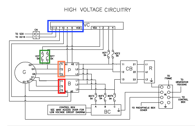
Figure 2

I Output Voltage Test:
1.Measuring the output voltage ensures that there is no issue with the rotor, the magnets, or the winding. Disconnect the output plug on the voltage controller (identified in blue, Figure 1).
2.Power up genset without a cargo load. The system should be running at 1500 rpm with the output plug of the voltage controller disconnected.
3.For the primary winding, measure primary phase voltages between the generator wires at the primary contactor (identified in orange, Figures 1 & 2):
a.T3-T2 (Generator leads: G6 - G4)
b.T2-T1 (Generator leads: G4 - G2)
c.T1-T3 (Generator leads: G2 - G6)
The three voltages that you measure should be within +/-10% of each other, and between 385 VAC and 460 VAC at generator temperatures between 20°F and 115°F (-7°C to 46°C) on the O.D. of the generator using an infra-red thermometer in the area identified (Figure 3). To verify you are within 10%, take the maximum reading minus the minimum reading and divide by the average of the max and the min. Results need to be less than 20%. (i.e. high 460, low 385, Results = 75 / 422 = 17%, good).
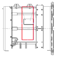
Figure 3
4.Record the voltage readings in the table below:
|
Voltage Readings |
|
|---|---|
|
T3-T2 (G6-G4) |
__________ Volts |
|
T2-T1 (G4-G2) |
__________ Volts |
|
T1-T3 (G2-G6) |
__________ Volts |
|
Voltage Readings |
|
|
Min Value |
__________ Volts |
|
Max Value |
__________ Volts |
|
Results |
__________ % |
5.Replace the generator if the calculation of the results above is bigger than 20%, otherwise proceed to step 6.
6.For the boost winding, measure boost phase voltages between the generator wires at the boost contactor (identified in red, Figures 1 & 2):
a.T3-T2 (Generator leads: G7 – G5)
b.T2-T1 (Generator leads: G5 – G1)
c.T1-T3 (Generator leads: G1 – G7)
The three voltages should each be within +/-10% of each other, and between 425 VAC and 508 VAC at generator temperatures between 20°F and 115°F (- 7°C to 46°C) using procedure noted above.
7.Record the voltage readings in the table below:
|
Voltage Readings |
|
|---|---|
|
T3-T2 (G7-G5) |
__________ Volts |
|
T2-T1 (G5-G1) |
__________ Volts |
|
T1-T3 (G1-G7) |
__________ Volts |
|
Voltage Readings |
|
|
Min Value |
__________ Volts |
|
Max Value |
__________ Volts |
|
Results |
__________ % |
8.Replace the generator if the calculation of the results is bigger than 20%, otherwise proceed to step 9.
II Resistance Test:
The resistance test checks if there are any shorts or opens in the winding.
Before measuring resistance, connect the leads to ensure the meter reads zero and is stable. Note: For field purposes you should be able to measure this resistance using a quality multimeter that is in good condition, though a four wire resistance meter would be better. The actual value, which is affected by temperature, is hard to measure accurately. It is less important than having a balanced reading across all three phases.
9.Power off the genset unit.
10.Open fuses VCF6 and VCF7 at the fuse block (circled in yellow, Figures 1 & 2).
11.For the primary winding, check the resistances between the generator wires (listed below) at the primary contactor (identified in orange, Figures 1 & 2):
a.T3-T2 (Generator leads: G6 – G4)
b.T2-T1 (Generator leads: G4 – G2)
c.T1-T3 (Generator leads: G2 – G6)
The three resistances that you measure should each be within +/-10% ohm of each other. To verify you are within the 10%, take the maximum reading minus the minimum reading and divide by the average of the max and the min. Results need to be less than 20%.
12.Record the resistance readings in the table below:
|
Resistance Readings |
|
|---|---|
|
T3-T2 (G6-G4) |
__________ Ohms |
|
T2-T1 (G4-G2) |
__________ Ohms |
|
T1-T3 (G2-G6) |
__________ Ohms |
|
Resistance Readings |
|
|
Min Value |
__________ Ohms |
|
Max Value |
__________ Ohms |
|
Results |
__________ % |
13.Replace the generator if the calculation of the results is bigger than 20%, otherwise proceed to step 14.
14.14. For the boost winding, check the resistances between the generator wires at the boost contactor (identified in red, Figures 1 & 2):
a.T3-T2 (Generator leads: G7 – G5)
b.T2-T1 (Generator leads: G5 – G1)
c.T1-T3 (Generator leads: G1 – G7)
The three resistances that you measure should each be within +/-10% ohm of each other. To verify you are within the 10%, take the maximum reading minus the minimum reading and divide by the average of the max and the min. Results need to be less than 20%.
15.Record the resistance readings in the table below:
|
Resistance Readings |
|
|---|---|
|
T3-T2 (G7-G1) |
__________ Ohms |
|
T2-T1 (G5-G1) |
__________ Ohms |
|
T1-T3 (G1-G7) |
__________ Ohms |
|
Resistance Readings |
|
|
Min Value |
__________ Ohms |
|
Max Value |
__________ Ohms |
|
Results |
__________ % |
16.Replace the generator if the calculation of the results above is bigger than 20%, otherwise proceed to step 17.
III Megger Test:
It is necessary to check the winding insulation resistances between the ground and each lead of the generator to ensure the insulation system of the generator is in good shape. A megger (or meg) test can catch an electrical short to ground where a standard ohm meter would not.
17.Power off the genset unit.
18.Open up all fuses (VCF1, VCF2, BCF3, BCF4, BCF5, VCF6 and VCF7) at the fuse block (identified in yellow, Figures 1 & 2)
19.Disconnect the generator ground wire G3 from the ground plate inside the receptacle box.
20.To perform this test, connect the first lead of the megger meter to the ground plate and attach the second lead of the megger meter to the generator at the primary and boost contactors T1, T2, and T3 (identified in yellow and orange, Figures 1 & 2).
21.Meg at 500 VDC (Note: A megger setting that is higher than 500 VDC may damage the generator windings). A high megger reading (min of 10 megaohms) would indicate a good insulation system.
22.Record the megger readings in the table below:
|
Megger Readings |
|
|---|---|
|
__________ Megaohms |
|
|
Ground -T2 (Ground - G4) |
__________ Megaohms |
|
Ground -T1 (Ground - G2) |
__________ Megaohms |
|
Ground -T3 (Ground - G7) |
__________ Megaohms |
|
Ground -T2 (Ground - G5) |
__________ Megaohms |
|
Ground -T1 (Ground - G1) |
__________ Megaohms |
|
Min Value |
__________ Megaohms |
23.Replace the generator if Min Value from the megger test above is less than 10 megaohms, otherwise the generator is good.
24.If a generator is found to have failed one of the tests (Output Voltage / Resistance / Megger) and is still under warranty, it is required that the Tier4 Generator Troubleshooting Checklist is filled out and sent to the Carrier Field Service Engineer of your region requesting an Authorization Number to return the faulty generator to Carrier Transicold.
Technician Certification
In May 2017, Carrier Transicold announced the training curricula for container associate and technician certifications with Service Bulletin (CTRSER017-002).
To register, go to the Carrier Container Training website.
Each level of certification, Associate and Technician, requires them to successfully complete and pass the required courses for the respective level.
Certification levels require a minimum amount of daily hands on experience, working with Carrier Container Equipment.
1. Carrier Container "Associates" Certification (Complete A and B)
a.Training (Complete either 1 or 2)
1.Complete and pass online modules 1, 2*, 3*, 4 (Either a or b), 5, 6, 7 (Either a or b) & 8
2.Complete and pass 3-day Associate Course
b.Complete 6 months of daily Hands On work experience.
2. Carrier Container "Technicians" Certification (Complete either A and B or C)
a.Training (Complete either 1, 2 or 3)
1.Complete and pass 1 week Container Technician course
2."On-Line" route
a) Successfully complete Carrier Container "Associates" Certification, and
b) Complete and pass alternate 4 and 7 modules not completed for "Associates" Certification, and
c) Complete and pass 2 day Container Technician course
3.Apprentice/College route
a) Complete an HVAC or equivalent apprenticeship, and
b) Complete and pass 3 day Container Technician course
b.Complete 12 months of daily Hands On work experience
c.Experience Route (Available until December 31, 2018)
1.Complete and pass 2-day Container Technician course
2.Complete 60 months of daily Hands On work experience
The relevant "Associates" or "Technicians" Certification must then be applied for. Certification requests application forms will become available in July 2017.
Carrier CareMAX Program Provider
As a follow-up to the TL2016_11, the following list of container locations have successfully implemented the refrigerant management policies and successfully completed the CareMAX™ program audit joining the CareMAX family.
We would like to congratulate the below companies for their achievement.
|
Company |
City |
Country |
|---|---|---|
|
Depot Zona Franca S.A. |
Barcelona |
Spain |
|
Eastern (1961) Company Pte. Ltd. |
Singapore |
Singapore |
|
JPC New Zealand Limited |
Auckland |
New Zealand |
|
JPC Reefer Services |
Brisbane |
Australia |
|
JPC Reefer Services |
Melbourne |
Australia |
|
Reefertec Pte Ltd |
Singapore |
Singapore |
|
Specialised Refrigeration Services (NZ) Ltd |
Napier |
New Zealand |
|
TRG Eastern Co Ltd |
Samutprakarn |
Thailand |
|
TRG Eastern Co Ltd |
Chonburi |
Thailand |
|
TRG Eastern Co Ltd |
Samutsakorn |
Thailand |
|
Pentalver Transport Ltd |
Felixstowe |
United Kingdom |
Global Training Schedule, 2017 Q3/Q4
Listed below are the instructor-led training courses scheduled through Q4 2017. Courses are subjected to a minimum requirement of 12 students.
Approximately 30 days prior to the class start date, registered students will receive an email confirming the class is being conducted along with logistical information. You should not make travel arrangements to attend the class until after you have received a confirmation email.
|
Region |
Start Date |
Course Description *Certificate |
Location |
|---|---|---|---|
|
APO |
09/18/2017 |
3-Day Basic Container Training Course |
Tauranga, New Zealand |
|
APO |
09/21/2017 |
2-Day Container Technician Certificate Course |
Tauranga, New Zealand |
|
APO |
10/16/2017 |
3-Day Basic Container Training Course |
Melbourne, Australia |
|
APO |
10/17/2017 |
3-Day Container Technician Certificate Course |
Bangkok, Thailand |
|
APO |
10/18/2017 |
2-Day Container Technician Certificate Course |
Kobe, Japan |
|
APO |
10/19/2017 |
2-Day Container Technician Certificate Course |
Melbourne, Australia |
|
APO |
10/23/2017 |
1 Week Container Technician Course |
Xiamen, China |
|
APO |
11/21/2017 |
3-Day Container Technician Certificate Course |
Davao, Philippines |
|
EMEA |
08/22/2017 |
3-Day Container Technician Certificate Course |
St. Petersburg, Russia |
|
EMEA |
08/29/2017 |
2-Day Container Technician Certificate Course |
Rotterdam, Netherlands |
|
EMEA |
09/05/2017 |
2-Day Container Technician Certificate Course |
Ashdod, Israel |
|
EMEA |
09/06/2017 |
3-Day Container Technician Certificate Course |
Barcelona, Spain |
|
EMEA |
09/13/2017 |
2-Day Container Technician Certificate Course |
Durban, South Africa |
|
EMEA |
09/19/2017 |
2-Day Container Technician Certificate Course |
Cape Town, South Africa |
|
EMEA |
10/03/2017 |
2-Day Container Technician Certificate Course |
Dubai, United Arab Emirates |
|
EMEA |
10/03/2017 |
3-Day Container Technician Certificate Course |
Antwerp, Belgium |
|
EMEA |
10/09/2017 |
2-Day Container Technician Certificate Course |
Salalah, Oman |
|
LAO |
08/07/2017 |
3-Day Container Technician Certificate Course |
Santos, Brazil |
|
LAO |
08/10/2017 |
2-Day Gen Set |
Santos, Brazil |
|
LAO |
08/21/2017 |
1 Week Container Technician Course |
Quetzal, Guatemala |
|
LAO |
08/22/2017 |
2-Day Container Technician Certificate Course |
Asuncion, Paraguay |
|
LAO |
09/04/2017 |
1 Week Container Technician Course |
Buenos Aires, Argentina |
|
LAO |
10/09/2017 |
1 Week Container Technician Course |
Manzanillo, Mexico |
|
NAO |
08/07/2017 |
1 Week Container Technician Course |
Long Beach, CA |
|
NAO |
08/21/2017 |
1 Week Container Technician Course |
Houston, TX |
|
NAO |
09/11/2017 |
1 Week Container Technician Course |
Montreal, Canada |
Listed are the software release versions for operating and working with Carrier Transicold units. Prior to upgrading software on units, you should seek agreement from the equipment owners.
Recip (ML2i / 5159, ML3, 5167), Scroll (ML2i, 5360 / ML3, 5368)
NaturaLINE 5704, Reciprocating Unit (ML2) – 1207 (New)
Controlled Atmosphere – 3115
DataLINE 3.1 (Windows 10 compatible), DataBANK 0513.
Menu – 0116, Software cards with revision greater than 5159 or 5361 must have menu 0116 or an error could occur.
After completing a software upgrade, verify the user selection settings (i.e. defrost, set point, etc.).
TechLINE is a publication of Carrier Transicold.
Editor / Contributor: Perry Hoover
Contributors: Oh Boon San, Barry Hofsdal, David Whyte, Tom Graf, Matt Schlote
Thanks to all who supported this release.