June 2016 Issue
Inside This Issue:
Micro-LINK® 2i / Analyzer
As a means of continual improvement, Carrier Transicold analyzes returned controllers in order to identify and act on opportunities for improvement. One of the leading classifications of controller failure is No Fault Found (NFF).
As part of Carrier’s NFF controller investigation process, a download analysis is performed. Upon evaluating the data, we can see that the controller was not run on the controller analyzer (an event is recorded in the datacorder documenting the use of the analyzer).
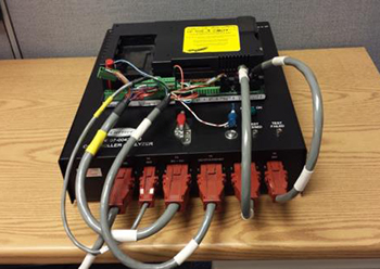
The Micro-LINK® 2i / 3 Controller Analyzer, part number 07-00428-00SV is an essential tool to eliminate these NFF failures. The analyzer is a standalone tool that operates at 115 VAC / 60 Hz or 220 VAC / 50Hz. As a standalone device, it is not impacted by the dynamic operating inputs that can make controller diagnosis in the unit difficult.
The operation of the analyzer is simple following the instructions (98-50600 Rev A) supplied. It uses LED status indicators on the analyzer to guide you through the complete I/O functionality check of the controller.
The controller does require software to be loaded on the PCMCIA card that’s provided with the tester. This software takes control of the controller and runs it though a complete group of tests. The latest software version can be downloaded from the Carrier Transicold Transcentral™ portal.
While connected to the analyzer, the controller datacorder can be downloaded for additional evaluation, if required.
The Micro-LINK Controller Analyzer can be purchased by contacting an authorized Carrier Transicold Service Provider.
When to Change an XtendFRESH™ O2 Sensor
There have been customer inquiries asking if the O2 sensor should be changed if it does not read 20.8% when exposed to normal ambient air. The response is no. Based on the manufactures specification and Carrier lab testing, a good sensor can read as low as 14.1% when exposed to normal ambient air and still perform properly in the 3% to 5% O2 control levels.
During “tESt” mode, the O2 sensor is checked to verify it is within an acceptable operating range. While performing the CO2 zero calibration, the software will perform an O2 sensor check to verify the sensor is capable of operating properly over the next voyage. If the sensor check reads the O2 sensor below 14.1%, it will post an “O2 Fail” message and the sensor will need to be changed.
The voltage range on the KD04 pin in open atmosphere will be between 2.00 and 3.6 VDC on a good sensor.
To determine if the O2 sensor needs to be changed, step 1 is to run test mode with the box exposed to normal atmospheric air, no cargo. If the O2 sensor passes, the sensor is acceptable for the next voyage. If the test posts “O2 Fail”, the sensor needs to be replaced.
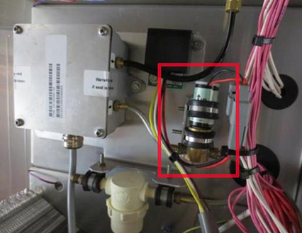
O2 Sensor Removal:
The O2 sensor can be removed from the fresh air panel by disconnecting the connector and removing the cushion clamp. Pull gently from brass holder.
Updated Recommendations for XtendFRESH™ System Curtain Installation
A key component to successful XtendFRESH system shipments is a sealed box. A major contributor to ensuring a box is sealed is proper installation of the curtain. The XtendFRESH option has been installed on container boxes with and without the CA track. Monitoring units over time has shown several effective methods for installing the curtain. These methods include closing the door over the curtain with the curtain showing around all four sides of the door, utilizing an existing CA track, or a combination of taping the curtain in place using double sided tape and closing the door around it.
Using magnets at the top of the container to hold the curtain will assist in alignment during installation.
Whichever method is selected by the customer, some basic practices need to be followed:
•Verify the door seals are in good condition.
•Ensure the door opening is free of debris, does not have sharp edges and is not rusted.
•Ensure the curtain does not have any holes.
•Ensure the cargo does not extend past the end of the T-Bars.
•When closing the door, ensure the curtain is not pulled by the door keepers.
•If CA track is used, inspect for sharp edges that may cut the curtain and verify that the track is correctly installed and mating edges are caulked.
DataLINE™ / USB / Com Port
Since the release in 2009 of the DataLINE™ diagnostic software version 1.9.1 (Service Pack 9), Carrier has introduced the Keyspan USB - RS232 adapter (CTD# 07-00503-00) for personal computers and laptops that do not have an RS-232 serial communication (or com) port, which is typically used to communicate with any Micro-LINK controller. With the appropriate driver of Keyspan USB - RS232 adapter installed, personal computers and laptops that do not have an RS-232 serial com port can continue to communicate with any Micro-LINK controller by using the USB port via the Keyspan USB - RS232 adapter.
As part of our ongoing review of procedures, we are issuing this procedure (in addition to the existing DataLINE Installation Instructions) to check and ensure that the Keyspan USB - RS232 adapter is properly installed and to perform a simple test (within office premises) before going out into the field for actual work.
Procedure:
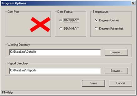
1.With Keyspan USB - RS232 adapter connected to the USB Port, launch the DataLINE Launch Pad Software and click on the Miscellaneous tab for “Program Options.
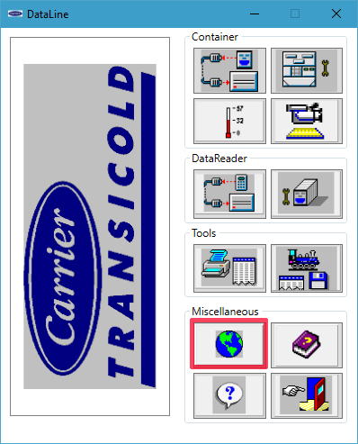
2.There should be a “Com Port” shown in the “Program Options” pop-up window indicating that DataLINE software has detected the Keyspan USB - RS232 adaptor and it is properly installed and connected. Proceed to step #9.
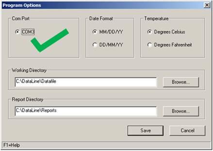
3.If the driver of Keyspan USB - RS232 adaptor is not properly installed, or Keyspan USB - RS232 adaptor is NOT connected, then no COM port will be shown. Continue with Step 4 to rectify the problem.
4.Verify the CCN Driver is not installed.
a.From Control Panel select either “Add/Remove Programs” or “Programs and Features,” so all programs installed are listed in alphabetical order.
b.Scroll down the list to look for “CCN Driver.”
c.Click “Remove” or “Uninstall,” to be guided through the uninstallation of CCN Driver.
d.After the uninstallation, select “No” when asked to restart the computer. Restart can be done when the last program is uninstalled.
5.Verify the USB-RS232 Driver is not installed.
a.From Control Panel select either “Add/Remove Programs” or “Programs and Features”, so all programs installed are listed in alphabetical order.
b.Scroll down the list to look for “USB-RS232 Driver”
c.Click “Remove” or “Uninstall”, to be guided throughout the uninstallation of USB-RS232 Driver.
d.After the uninstallation is completed, select “No” when asked to restart the computer. Restart can be done when the last program is uninstalled.
If you have a Prolific USB driver in your list, this should be left installed as you have another program that requires this driver.
6.Verify the Keyspan USB - RS232 adapter Driver is properly installed.
a.From the Control Panel, select either “Add/Remove Programs” or “Programs and Features,” so all programs installed are listed in alphabetical order.
b.Scroll down the list to look for “Keyspan USB Serial Adaptor.”
c.If it is installed take no action, otherwise install it from the CD supplied with the Keyspan USB/RS232 adaptor
7.Restart the personal computer or laptop to ensure that the changes have taken place.
8.Repeat steps 1 and 2 to verify COM port is now installed.
9.The setup is complete and DataLINE software is ready for use.
Tier 4 Generator Troubleshooting
On analysis of returned generator, significant portions were identified as No Fault Found (NFF) which would indicate a mis-diagnosis of a failure.
To reduce the number of these NFF Tier 4 generators, the following procedures have been identified and are intended to assist the technician in troubleshooting Tier 4 genset unit generators.
Before proceeding with the troubleshooting, make sure to follow your company’s standard safety procedures for working with electrical components.
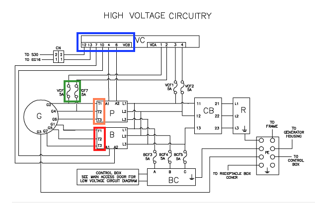
Circled in yellow, red, orange and blue are reference points called out in the troubleshooting procedures.
To troubleshoot a generator with a suspected electrical issue in the field, we recommend the following:

I Output Voltage Test:
Measuring the output voltage ensures that there is no issue with the rotor, the magnets, or the winding:
1.Disconnect the output plug on the voltage controller (identified in blue, Figure 1).
2.Power up the genset unit without a cargo load. The system should be running at 1500 rpm with the output plug of the voltage controller disconnected.
3.For the primary winding, measure primary phase voltages between the generator wires at the primary contactor (identified in orange, Figures 1 & 2).
a.T3-T2 (Generator leads: G6 - G4)
b.T2-T1 (Generator leads: G4 - G2)
c.T1-T3 (Generator leads: G2 - G6)
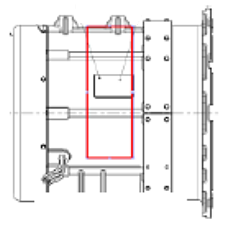
The three voltages that you measure should be within +/-10% of each other, and between 385 VAC and 460 VAC at generator temperatures between 20°F and 115°F (-7°C to 46°C) on the O.D. of the generator using an infra-red thermometer in the area identified (Figure 3). To verify you are within the 10%, take the maximum reading minus the minimum reading and divide by the average of the max and the min. Results need to be less than 20%. (I.e. high 460, low 385 = (75 / 422 = 17%), good).
4.For the boost winding, measure boost phase voltages between the generator wires at the boost contactor (identified in red, Figures 1 & 2).
a.T3-T2 (Generator leads: G7 - G7)
b.T2-T1 (Generator leads: G5 - G1)
c.T1-T3 (Generator leads: G1 - G7)
The three voltages should each be within +/-10% of each other, and between 425 VAC and 508 VAC at generator temperatures between 20°F and 115°F (-7°C to 46°C) using procedure noted above.
II Resistance Test:
The resistance test checks if there are any shorts or opens in the winding:
Before measuring resistance connect the leads to ensure the meter reads zero and is stable.
1.Power off the genset unit.
2.Open the fuses VCF6 and VCF7 at the fuse block (circled in yellow, Figures 1 & 2).
3.For the primary winding, check the resistances between the generator wires (listed below) at the primary contactor (identified in orange, Figures 1 & 2):
a.T3-T2 (Generator leads: G6 - G4)
b.T2-T1 (Generator leads: G4 - G2)
c.T1-T3 (Generator leads: G2 - G6)
The three resistances that you measure should each be within +/-10% ohm of each other.
4.For the boost winding, check the resistances between the generator wires at the boost contactor (identified in red, figures 1 & 2):
a.T3-T2 (Generator leads: G7 - G5)
b.T2-T1 (Generator leads: G5 - G1)
c.T1-T3 (Generator leads: G1 - G7)
The three resistances that you measure should each be within +/-10% ohm of each other.
For field purposes you should be able to measure this resistance using a quality multimeter that is in good condition, though a four wire resistance meter would be better. The actual value, which is affected by temperature and hard to measure accurately, is less important than having a balanced reading across all three phases.
III Megger Test:
It is necessary to check the winding insulation resistances between the ground and each lead of the generator to ensure the insulation system of the generator is in good shape. A megger (or meg) test can catch an electrical short to ground where a standard ohm meter would not.
1.Power off the genset unit.
2.Open up all fuses (VCF1, VCF2, BCF3, BCF4, BCF5, VCF6 and VCF7) at the fuse block (identified in yellow, Figures 1 & 2).
3.Disconnect the generator ground wire G3 from the ground plate inside the receptacle box.
4.To perform this test, connect the first lead of the megger meter to the ground plate and attach, distinctly every time, the second lead of the megger meter to each lead of the generator at the primary and boost contactors T1, T2, and T3 (identified in yellow and orange, Figures 1 & 2).
5.Meg at 500 VDC. A megger setting that is higher than 500 VDC may damage the generator windings). A high megger reading (min of 10 megaohms) would indicate a good insulation system.
If a generator is found to have failed one of the tests and is still under warranty, it is required that the results of the tests are on both the warranty claim description and the MPR (Mandatory Parts Return) tag attached to the generator.
Properly tagging the generator will help in identifying the root cause failure.
Global Training Schedule, 2016 Q3/Q4
.Listed below are the instructor-led training courses scheduled through Q4 2016. Courses are subjected to a minimum requirement of 12 students.
Approximately 30 days prior to the class start date, registered students will receive an email confirming the class is being conducted along with logistical information. You should not make travel arrangements to attend the class until after you have received a confirmation email.
|
Region |
Start Date |
Course Description |
Location |
|
APO |
8/8/2016 |
3-Day Basic Container Update |
Melbourne, Australia |
|
APO |
8/11/2016 |
2-Day Container Product Update |
Melbourne, Australia |
|
APO |
09/12/2016 |
1-Week Container |
Cochin, India |
|
APO |
09/14/2016 |
Basic2-Day Gen Set |
Melbourne, Australia |
|
APO |
10/18/2016 |
3-Day Basic Container Update |
Bangkok, Thailand |
|
APO |
10/19/2016 |
2-Day Container Product Update |
Busan, Korea |
|
APO |
10/26/2016 |
2-Day Container Product Update |
Yokohama, Japan |
|
APO |
11/16/2016 |
2-Day Container Product Update |
Brisbane, Australia |
|
LAO |
7/4/2016 |
1-Week Container Basic |
Valparaiso, Chile |
|
LAO |
7/11/2016 |
1-Week Container Basic |
Puerto Cortes, Honduras |
|
LAO |
7/28/2016 |
2-Day Controlled Atmosphere |
Valparaiso, Chile |
|
LAO |
8/8/2016 |
1-Week Container Basic |
San Juan, Puerto Rico |
|
LAO |
8/29/2016 |
3-Day Advanced Container Update |
Salvador, Brazil |
|
LAO |
9/1/2016 |
2-Day Gen Set |
Salvador, Brazil |
|
LAO |
10/03/2016 |
1-Week Container Basic |
Rio Grande, Brazil |
|
LAO |
10/17/2016 |
1-Week Container Basic |
Costa Rica |
|
NAO |
8/16/2016 |
2-Day Container Product Update |
Vancouver, Canada |
|
NAO |
8/18/2016 |
2-Day Gen Set |
Vancouver, Canada |
|
NAO |
8/22/2016 |
3-Day Advanced Container Update |
Oakland, CA |
|
NAO |
8/25/2016 |
2-Day Gen Set |
Oakland, CA |
|
NAO |
9/12/2016 |
1-Week Container Basic |
Miami, FL |
|
NAO |
9/19/2016 |
1 Week Container Basic |
Norfolk, VA |
|
NAO |
10/24/2016 |
3-Day Advanced Container Update |
Seattle, WA |
|
NAO |
10/27/2016 |
2-Day Gen Set |
Seattle, WA |
|
NAO |
10/31/2016 |
3-Day Advanced Container Update |
Long Beach, CA |
|
NAO |
11/03/2016 |
2-Day Gen Set |
Long Beach, CA |
|
NAO |
11/7/2016 |
1-Week Container Basic |
Jacksonville, FL |
Software Release Update
Listed are the software release versions for operating and working with Carrier Transicold units. Prior to upgrading software on units, you should seek agreement from the equipment owners.
Recip (ML2i / 5159, ML3, 5165), Scroll (ML2i, 5360 /ML3, 5365)
Reciprocating Unit (ML2) – 1207
Controlled Atmosphere – 3115
DataLINE 2.2 (Windows 8 compatible), DataBANK 0513.
Menu – 0116, Software cards with revision greater than 5159 or 5361 must have menu 0116 or an error could occur.
After completing a software upgrade, verify the user selections (i.e. defrost, set point, etc.).
TechLINE is a publication of Carrier Transicold.
Editor / Contributor: Perry Hoover
Contributors: Oh Boon San, Barry Hofsdal, Mark Donahoe, Nadir Guenane
Thanks to all who supported this release.