Section 3
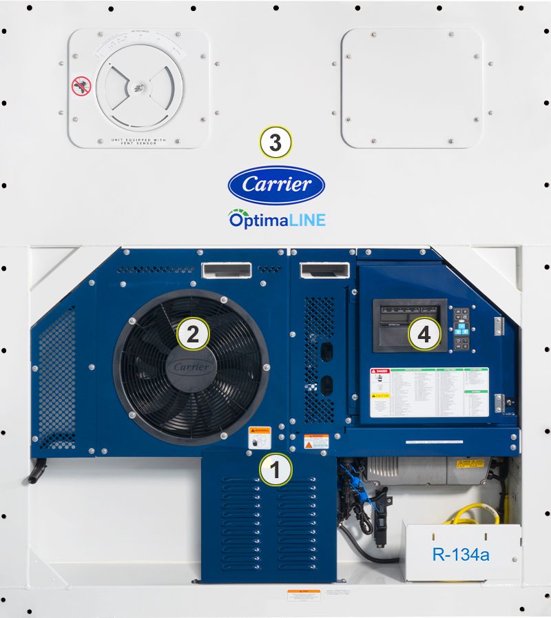
The container unit, shown in Figure 3.1, is designed so that the majority of the components are accessible from the front. The unit model number, unit serial number and parts identification number can be found on the unit nameplate on the side wall next to the power cable storage area.
Figure 3.1 Container Unit - Front Section
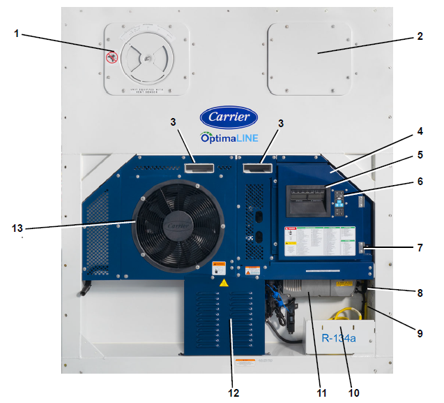
1)Access Panel with Fresh Air Makeup Vent (Evaporator Fan location)
2)Access Panel (Evaporator Fan location)
3)Fork Lift Pockets
4)Control Panel
5)Unit Display
6)Keypad
7)Start-Stop Switch (ST)
8)Unit Nameplate
9)Options Label and PED Label
10)Power Cables and Plug
11)Variable Frequency Drive (VFD)
12)Compressor (behind guard)
13)Condenser Fan and Coil
- - - - -
The container unit components, as shown in Figure 3.2, are explained in this manual by dividing into four sections:
1.Compressor section
2.Condenser section
3.Evaporator section
4.Control box section
Figure 3.2 Container Unit Sections
The compressor is a variable speed scroll compressor that receives refrigerant vapor from the evaporator and compresses it to a high pressure, high temperature gas before directing it to the condenser.
The compressor section includes a compressor, variable frequency drive (VFD), discharge service valves (discharge and suction), discharge pressure transducer (DPT), suction pressure transducer (SPT), evaporator pressure transducer (EPT), a high pressure switch (HPS), a discharge temperature sensor (CPDS) and connections to the compressor.
Compressor section components are shown in Figure 3.3 and Figure 3.4.
The air-cooled condenser removes latent heat from the refrigerant gas by using a condenser fan to blow air across the condenser coil fins and tubes to cool the gas to saturation temperature. The condenser fan pulls air from around the coil and discharges it horizontally through the condenser fan grille.
The condenser section, includes the following components: condenser fan and coil, receiver with sight glass & indicator, liquid line service valve, filter drier, economizer, economizer expansion valve (ECV) economizer pressure transducer (ECP) and economizer temperature sensor (ECT).
Condenser section components are shown in Figure 3.3 and Figure 3.4.
The evaporator fans circulate air through the container by pulling it from the top of the unit, through the evaporator coil to be heated or cooled, and discharging it at the bottom of the refrigeration unit into the container.
The evaporator section, includes the following components: evaporator fan and motor (EM1, EM2), return temperature sensor (RTS), return recorder sensor (RRS), humidity sensor (HS), evaporator coil, heaters, heat termination thermostat (HTT), defrost temperature sensor (DTS), electronic expansion valve (EEV), evaporator temperature sensor (ETS), receptacles, and interrogator connector.
Evaporator section components are shown in Figure 3.5.
The control box section includes the display module and keypad on the control box door and the start/stop switch mounted to the right of the door. Inside the door are the unit controller (control module), controller battery pack, circuit breaker (CB1), contactors for the compressor, fans and heater, fuses, control power transformer, transformer AC line filter and the current sensor module.
Control box section components are shown in Figure 3.6.
The unit controller, display module and keypad are described in the Microprocessor chapter, see Section 4.1.
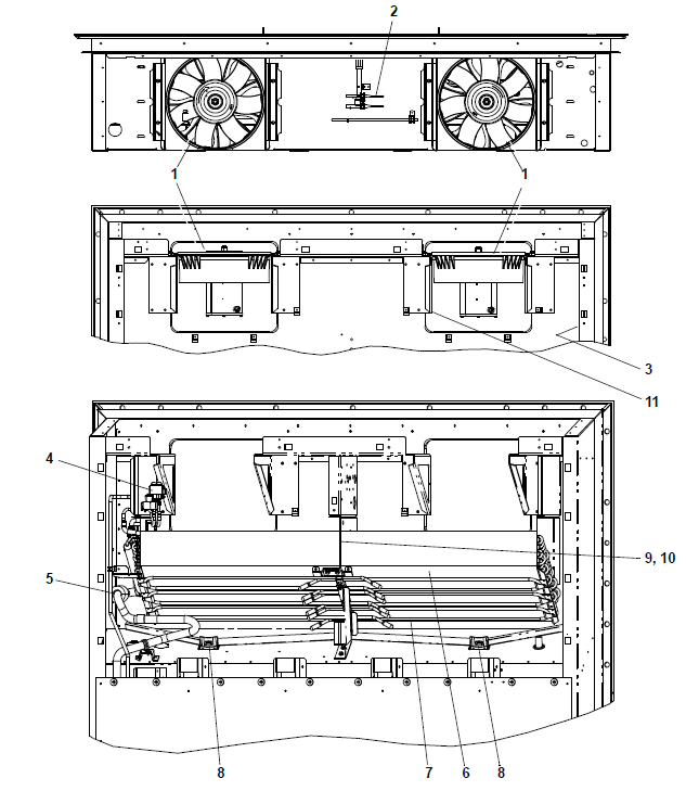
Figure 3.3 Compressor and Condenser Sections
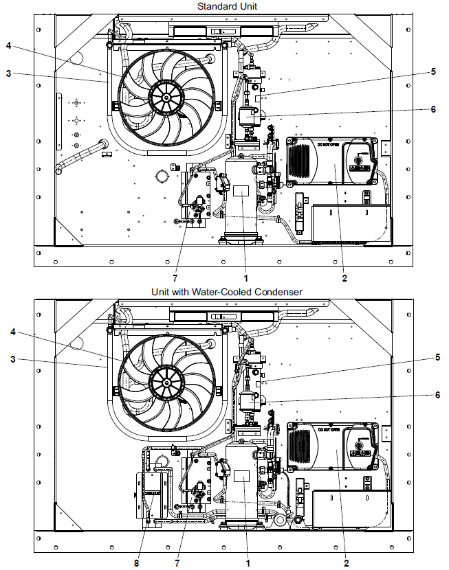
1)Compressor
2)Variable Frequency Drive (VFD)
3)Condenser Coil, MCHE
4)Condenser Fan and Motor
5)Receiver with Sight Glass and Moisture Indicator
6)Filter Drier
7)Economizer
8)Water Cooled Condenser (Option)
- - - - -
Figure 3.4 Compressor and Condenser Sections
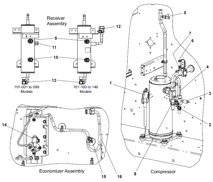
1)Compressor Terminal Box
2)Discharge Service Valve
3)High Pressure Switch (HPS)
4)Discharge Temperature Sensor (CPDS)
5)Discharge Pressure Transducer (DPT)
6)Suction Pressure Transducer (SPT)
7)Evaporator Pressure Transducer (EPT)
8)Suction Service Valve
9)Receiver Sight Glass
10)Receiver Moisture Indicator
11)Fusible Plug (701-001 to 099 Models)
12)Pressure Relief Valve (701-100 to 149 Models)
13)Liquid Line Service Valve / King Valve
14)Economizer Expansion Valve (ECV)
15)Economizer Pressure Transducer (ECP)
16)Economizer Temperature Sensor (ECT)
- - - - -
Figure 3.5 Evaporator Section
1)Evaporator Fan and Motor (EM1, EM2)
2)Return Temperature Sensor (RTS) / Return Recorder Sensor (RRS)
3)Humidity Sensor (HS)**
4)Electronic Expansion Valve (EEV)
5)Evaporator Temperature Sensors (ETS1 / ETS2)
6)Evaporator Coil
7)Heaters (6)
8)Defrost Drain
9)Heat Termination Thermostat (HTT)**
10)Defrost Temperature Sensor (DTS)**
11)Vent Position Sensor (VPS), if installed**
- - - - -
** general location, not shown in figure.
Figure 3.6 Control Box Section
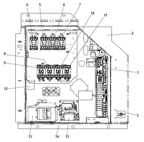
1)Controller
2)Controller Battery Pack and Battery
Note: located above controller (not shown)
3)Start/Stop Switch
4)Compressor Contactor (CH)
5)Compressor Phase A Contactor (PA)
6)Compressor Phase B Contactor (PB)
7)Heater Contactor (HR)
8)Condenser Fan Contactor Low Speed (CL)
9)Condenser Fan Contactor High Speed (CF)
10)Low Speed Evaporator Fan Contactor (ES)
11)High Speed Evaporator Fan Contactor (EF)
12)Current Sensor Module
13)Circuit Breaker (CB1) 460V
14)Control Transformer
15)Transformer AC Line Filter
- - - - -
3.3Main Component Descriptions
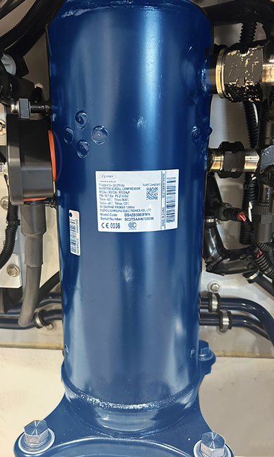
The compressor, shown in Figure 3.7, receives refrigerant vapor from the evaporator and compresses it to a high pressure, high temperature gas before directing it to the condenser. The compressor contains a terminal box, oil drain, refrigerant discharge and suction connections.
Figure 3.7 Compressor
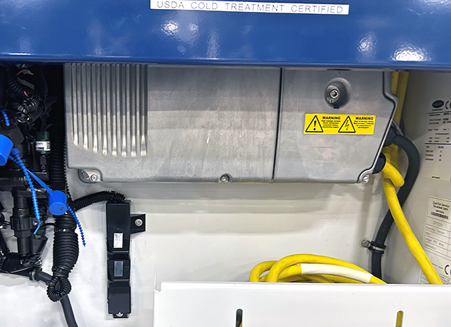
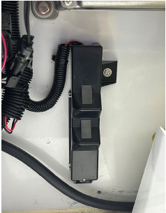
The variable frequency drive (VFD), shown in Figure 3.8, drives the compressor variable speed motor.
NOTE: The VFD has permanent magnet motor control, and therefore it is not possible to bypass the VFD.
Figure 3.8 Variable Frequency Drive (VFD)
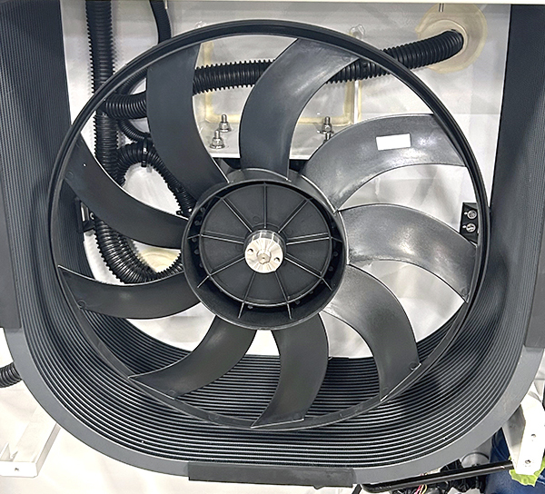
From the compressor, the refrigerant flows to the air-cooled condenser, shown in Figure 3.9. The condenser fan blows the air across the coil fins and tubes to cool the gas to saturation temperature. By removing latent heat, the gas condenses to a high pressure / high temperature liquid and flows to the receiver. The fan is dual speed to enable low speed operation under light load.
Figure 3.9 Condenser Coil and Fan (Cover Removed)
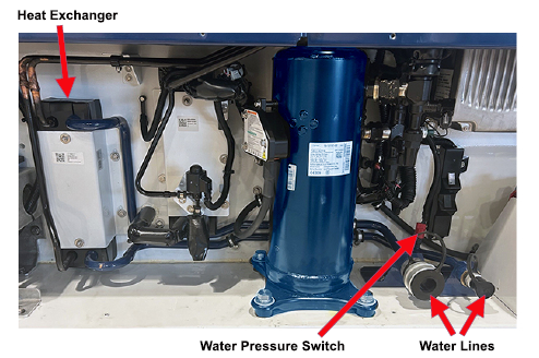
3.3.4Water-Cooled Condenser Option
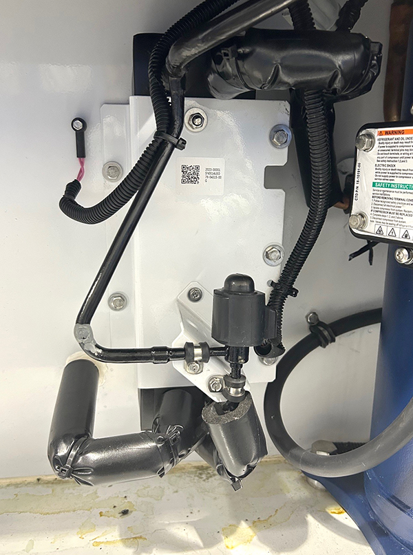
The unit may contain an optional brazed plate water-cooled condenser (WCC), shown in Figure 3.10. The WCC contains a heat exchanger, water lines and a water pressure switch. When operating with a WCC, the condenser fan is deactivated by the water pressure switch. The receiver is retained in this configuration and the WCC is placed between the air-cooled condenser and the receiver.
Figure 3.10 Brazed Plate Water-Cooled Condenser
The receiver, shown in , receives high pressure / high temperature liquid refrigerant from the condenser and stores it for when it is needed during low temperature operation. The receiver contains a sight glass, moisture indicator and fusible plug.
R-513A-ready units (models 701-001 to 099) have a receiver, Figure 3.11, with a fusible plug.
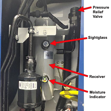
R1234yf-ready units (models 701-100 to 149) have a receiver, Figure 3.12, with a pressure relief valve (PRV).
Figure 3.11 Receiver with Fusible Plug
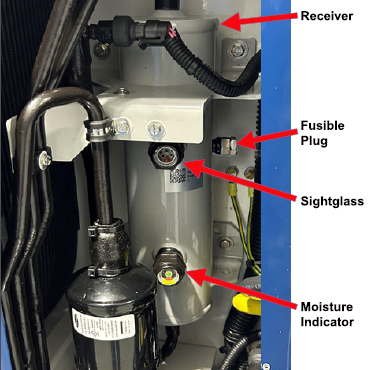
Figure 3.12 Receiver with Pressure Relief Valve
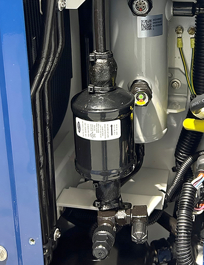
Refrigerant flows from the receiver through the filter drier, shown in Figure 3.13, which removes particulates and small amounts of water from the refrigerant to keep it clean and dry.
Figure 3.13 Filter Drier
The economizer, shown in Figure 3.14, is only active when the unit enables economized mode and the controller energizes the economizer expansion valve (ECV), see Figure 3.22. The liquid refrigerant flows through the ECV to the economizer internal passages, absorbing heat from the liquid refrigerant flowing to the electronic expansion valve (EEV). The resultant “medium” temperature / pressure gas is directed back to the compressor.
If economized mode is not active, the economizer is bypassed and refrigerant flows directly to the EEV.
NOTE: The EEV position (%) reading can be viewed on the unit display at function code Cd54.
Figure 3.14 Economizer
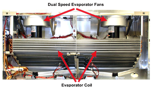
Refrigerant enters the evaporator coil, shown in Figure 3.15, as a low pressure, low temperature saturated mixture and exits as a vapor. As the refrigerant enters the coil, two dual speed evaporator fans blow air on the coil. Heat is absorbed from the air by the balance of the liquid, causing it to vaporize in the coil. And the cooler air is returned to the container unit.
Figure 3.15 Evaporator Coil and Fans
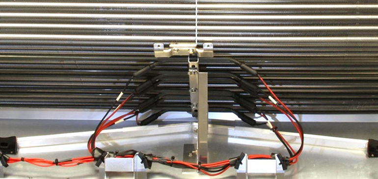
The heaters, shown in Figure 3.16, are energized when Heating mode or Defrost mode is called for by the controller.
Figure 3.16 Heaters
3.3.10Heat Termination Thermostat
The heat termination thermostat (HTT), shown in Figure 3.17, is a safety device attached to an evaporator coil circuit that opens the heating circuit if overheating occurs.
Figure 3.17 Heat Termination Thermostat (HTT)
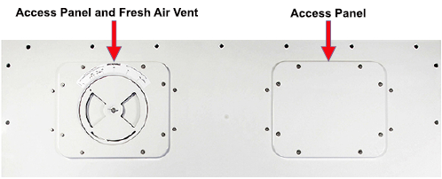
3.3.11Evaporator Access Panels and Air Makeup Vent
Most evaporator components are accessible by removing the upper back rear panel, inside the container unit. They may also be accessed via the evaporator fan access panels on the front of the unit, as shown in Figure 3.18.
The left access panel contains the fresh air makeup vent, which is a manually operated venting system that provides ventilation for commodities that require fresh air circulation. The fresh air makeup vent may be equipped with an optional vent position sensor (VPS) that determines the vent position.
Refer to Section 5.5 for the procedure to adjust the fresh air makeup vent.
NOTE: If a VPS is installed, fresh air vent position is viewed on the unit display at function code Cd45.
Figure 3.18 Access Panels and Fresh Air Makeup Vent
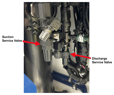
3.4Service Valves Descriptions
3.4.1Compressor Service Valves
The discharge service valve and suction service valve, shown in Figure 3.19, allow connecting of the manifold gauge set to perform refrigerant service. The service valves are provided with a double seat and an access valve which enables servicing of the compressor and refrigerant lines.
Figure 3.19 Compressor Service Valves
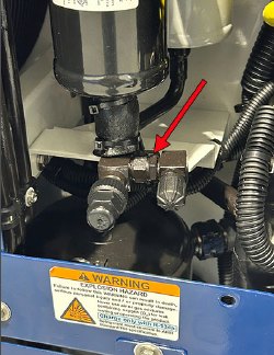
3.4.2Liquid Line Service Valve
The liquid line service valve or king valve, shown in Figure 3.20, is for service procedures related to adding and removing refrigerant.
Figure 3.20 Liquid Line / King Valve
3.5Refrigerant Valves Descriptions
3.5.1Electronic Expansion Valve
The electronic expansion valve (EEV), shown in Figure 3.21, drops the pressure of the liquid refrigerant to suction pressure. As this happens, some of the liquid vaporizes to a gas (flash gas), removing heat from the remaining liquid. The liquid is then sent to the evaporator as a low pressure, low temperature, saturated mix.
NOTE: The EEV position (%) can be viewed on the unit display at function code Cd54.
Figure 3.21 Electronic Expansion Valve (EEV)
3.5.2Economizer Expansion Valve
The economizer expansion valve (ECV), shown in Figure 3.22, is energized during Economized mode. The liquid refrigerant flows through the ECV to the economizer internal passages, absorbing heat from the liquid refrigerant flowing to the electronic expansion valve (EEV). The resultant “medium” temperature / pressure gas is directed back to the compressor.
NOTE: The ECV position (%) can be viewed on the unit display at function code Cd86.
Figure 3.22 Economizer Expansion Valve (ECV)
3.6Refrigerant Probes Description
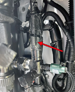
3.6.1Compressor Discharge Temperature Sensor
The compressor discharge temperature sensor (CPDS), shown in Figure 3.23, measures the temperature of the refrigerant as it is discharged from the compressor.
NOTE: The CPDS reading can be viewed on the unit display at function code Cd11.
Figure 3.23 Compressor Discharge Temperature Sensor (CPDS)
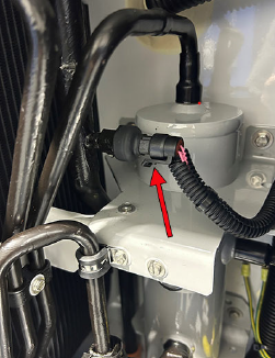
The high pressure switch (HPS), shown in Figure 3.24, monitors abnormally high discharge pressure. It opens at 25 (+/- 1.0) kg/cm2 | 350 (+/- 10) psig.
Figure 3.24 High Pressure Switch (HPS)
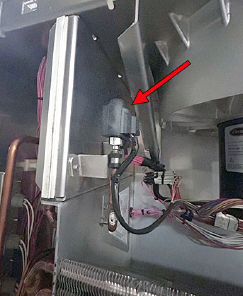
3.6.3Discharge Pressure Transducer
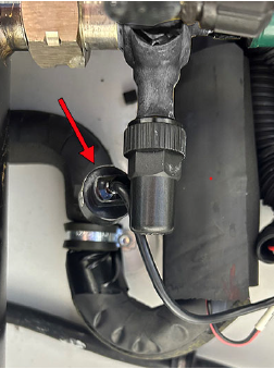
The discharge pressure transducer (DPT), shown in Figure 3.25, monitors refrigerant pressure on the discharge side of the compressor. The DPT is located behind the receiver.
NOTE: The DPT reading can be viewed on the unit display at function code Cd14.
Figure 3.25 Discharge Pressure Transducer (DPT)
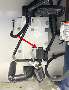
3.6.4Economizer Pressure Transducer
The economizer pressure transducer (ECP), shown in Figure 3.26, monitors refrigerant pressure between the economizer and the compressor. It is located near the economizer connection to the compressor.
NOTE: The ECP reading can be viewed on the unit display at function code Cd85.
Figure 3.26 Economizer Pressure Transducer (ECP)
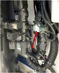
3.6.5Economizer Temperature Sensor
The economizer temperature sensor (ECT), shown in Figure 3.27, monitors refrigerant temperature between the economizer and the compressor. It is located near the economizer connection to the compressor.
NOTE: The ECP reading can be viewed on the unit display at function code Cd84.
Figure 3.27 Economizer Temperature Sensor (ECT)
3.6.6Evaporator Temperature Sensor
The evaporator temperature sensor (ETS1 / ETS2), shown in Figure 3.28, records the temperature of the refrigerant leaving the evaporator. It is located to the side of the evaporator coil.
NOTE: The ETS reading can be viewed on the unit display at function code Cd10.
Figure 3.28 Evaporator Temperature Sensor (ETS1 / ETS2)
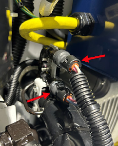
3.6.7Evaporator / Suction Pressure Transducer
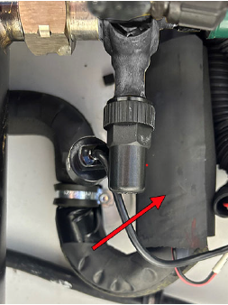
The evaporator pressure transducer (EPT) and suction pressure transducer (SPT), shown in Figure 3.29 , monitors refrigerant on the suction side of the compressor.
NOTE: The EPT and SPT readings can be viewed on the unit display at function code Cd12.
Figure 3.29 Evaporator Pressure Transducers - EPT (bottom) and SPT (top)
3.7Air Stream Sensors Descriptions
3.7.1Supply Temperature Sensors
The supply temperature sensor (STS) and supply recorder sensor (SRS) are shown in Figure 3.30. The STS monitors the supply air temperature as it enters the container unit near the unit floor. The controller maintains the supply air temperature at setpoint during Perishable mode according to the STS. The SRS is for recording temperature and also to backup the STS in case of failure. See Section 4.3.2 for details on Perishable mode.
NOTE: The SRS reading can be viewed on the unit display at function code dC1.
Figure 3.30 Supply Temperature Sensor (STS) / Supply Recorder Sensor (SRS)
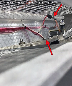
3.7.2Return Temperature Sensors
The return temperature sensor (RTS) and return recorder sensor (RRS) are shown in Figure 3.31. The RTS monitors the return air temperature at the top of the container unit above the evaporator fans. The controller maintains the return air temperature at setpoint during frozen mode according to the RTS. The RRS is for recording temperature and also to backup the RTS in case of failure. See Section 4.3.3 for details on frozen mode.
NOTE: The RRS reading can be viewed on the unit display at function code dC2.
Figure 3.31 Return Temperature Sensor (RTS) / Return Recorder Sensor (RRS)
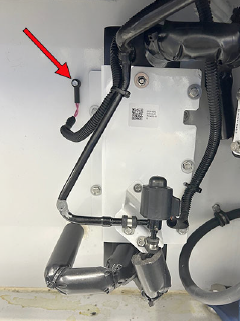
3.7.3Ambient Temperature Sensor
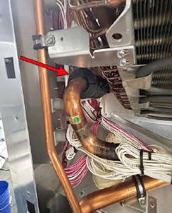
The ambient temperature sensor (AMBS), shown in Figure 3.32, measures ambient temperature that the controller monitors to adjust operating modes accordingly inside the unit. It is located next to the economizer.
NOTE: The DTS reading can be viewed on the unit display at function code Cd09.
Figure 3.32 Ambient Temperature Sensor (AMBS)
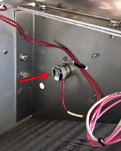
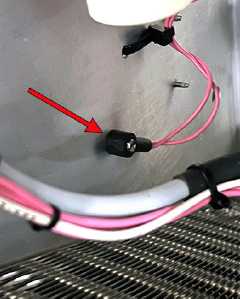
3.7.4Defrost Temperature Sensor
The defrost temperature sensor (DTS), shown in Figure 3.33, determines the initiation of Defrost mode. When the DTS senses a temperature less than 10°C (50°F), the defrost options become active and the timer is engaged for the initiation of the defrost cycle. See Section 4.3.4 for more information on defrost mode.
NOTE: The DTS reading can be viewed on the unit display at function code Cd26.
Figure 3.33 Defrost Temperature Sensor (DTS)
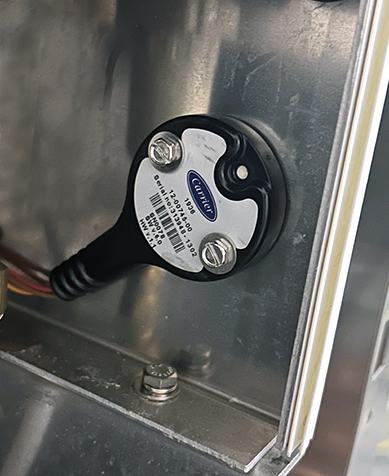
The humidity sensor (HS), shown in Figure 3.34, is an optional component that detects the relative humidity inside the container unit.
NOTE: The HS reading of relative humidity (%) can be viewed on the unit display at function code Cd17.
NOTE: The humidity settings are controlled on the unit display at function code Cd48.
Figure 3.34 Humidity Sensor (HS)
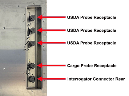
3.7.6USDA Probes and Cargo Probe
If equipped, the unit has the capability of recording three USDA probes (USDA 1-3) and one cargo probe. The 3-pin receptacles for plugging in the probes are located in the evaporator section. The probe leads are plugged into the desired receptacle, shown in Figure 3.35. There is also a 5-pin interrogator receptacle (ICR) for third party device connectivity.
NOTE: USDA probe readings can be viewed on the unit display at function codes dC3, dC4 and dC5.
NOTE: The cargo probe reading can be viewed on the unit display at function code dC14.
Figure 3.35 Receptacles
The EverFRESH® controlled atmosphere option controls container atmosphere by supplying nitrogen and oxygen into the container space and simultaneously controlling levels of oxygen and carbon dioxide. Units with EverFRESH installed will typically have the label placed on the access panel.
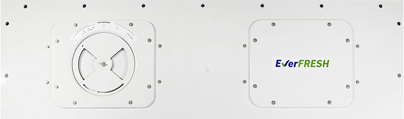
For units with EverFRESH installed, an air compressor is installed under the condenser and several other components located in the evaporator section inside the access panels. See Section 5.9.6 for enabling or disabling EverFRESH operation on the unit.
NOTE: EverFRESH is controlled on the unit display from function codes Cd44, Cd71 and Cd76.
Detailed procedures and technical information related to the EverFRESH controlled atmosphere system are included in the separate T-374 EverFRESH Manual. This can be found in the ContainerLINK™ app or from the Literature section of the Container Refrigeration website.
EXPLOSION HAZARD: Failure to follow this WARNING can result in death, serious personal injury and / or property damage. Never use air or gas mixtures containing oxygen (O2) for leak testing or operating the product. Charge only with refrigerants R-134a or R-513A as specified for the unit model number. Refrigerant must conform to AHRI Standard 700 specification.
Charge receiver according to nameplate specifications to ensure optimal unit performance.
Table 3–1 Refrigeration System Data
|
Compressor / Motor Assembly |
Model Number |
DS4ZB5080FMN |
|
Type |
Hermetically Sealed Variable Speed Scroll type |
|
|
Weight (With Oil) |
43.1 kg (95 lb) |
|
|
Approved Oil |
Idemitsu FW56EA |
|
|
Oil Charge |
1300 ml (44 ounces) |
|
|
Electronic Expansion Valve Superheat (Evaporator) |
Variable |
|
|
Economizer Expansion Valve Superheat |
Variable |
|
|
Heater Termination Thermostat |
Opens |
54° (+/- 3) C | 130° (+/- 5) F |
|
Closes |
38° (+/- 4) C | 100° (+/- 7) F |
|
|
High Pressure Switch (HPS) |
Cut-Out |
25 (+/- 1.0) kg/cm2 | 350 (+/- 10) psig |
|
Cut-In |
18 (+/- 0.7) kg/cm2 | 250 (+/- 10) psig |
|
|
Refrigerant |
R-134a / R-513A |
Conforming to AHRI standard 700 specifications. |
|
Refrigerant Charge |
Receiver |
R-134a refrigerant: 4.32 kg (9.5 lbs) Charge for other refrigerants to be included in instructions provided in Service Kit. |
| Pressure Relief Valve | Set Pressure, Opens | 27.6 bar = 400 psig |
| Torque | 113 to 123 Nm (83 to 91 ft-lbs) | |
|
Unit Weight |
Refer to unit nameplate. See Figure 2.1 |
|
|
Circuit Breaker |
CB-1 |
25 amps |
|
|
Condenser Fan Motor |
Nominal Supply |
380 VAC, 3 Phase, |
460 VAC,3 Phase, |
|
Full Load Amps (H / L) |
1.0 / 0.6 amps |
1.0 / 0.6 amps |
|
|
Horsepower (H / L) |
0.21 hp / 0.03 hp |
0.36 hp / 0.04 hp |
|
|
RPM (H / L) |
1450 / 725 rpm |
1750 / 850 rpm |
|
|
Voltage Range |
360 - 460 VAC |
400 - 500 VAC |
|
|
Bearing Lubrication |
Factory lubricated, additional grease not required. |
||
|
Rotation |
Counter-clockwise when viewed from shaft end. |
||
|
Evaporator Coil Heaters |
Number of Heaters |
6 |
|
|
Rating |
750 watts +5/-10% each @ 230 VAC |
||
|
Resistance (cold) |
66.8 to 77.2 ohms @ 20°C (68°F) |
||
|
Type |
Sheath |
||
|
Evaporator Fan Motor(s) |
Nominal Supply |
380 VAC, 3 Phase, |
460 VAC, 3 Phase, |
|
Full Load Amps (H / L) |
1.07 / 0.47 |
0.9 / 0.47 |
|
|
Nominal Horsepower (H / L) |
0.36 / 0.05 |
0.63 / 0.08 |
|
|
RPM (H / L) |
2850 / 1425 rpm |
3450 / 1725 rpm |
|
|
Voltage Range |
360 - 460 VAC |
400 - 500 VAC |
|
|
Bearing Lubrication |
Factory lubricated, additional grease not required |
||
|
Rotation |
CW when viewed from shaft end |
||
|
Fuses |
Control Circuit |
7.5 amps (F3, F4) |
|
|
Controller / DataCORDER |
7.5 amps (F1, F2) |
||
|
Vent Positioning Sensor |
Electrical Output |
0.5 to 4.5 VDC over 90 degree range |
|
|
Supply Voltage |
5 VDC +/- 10% |
||
|
Supply Current |
5 mA (typical) |
||
|
Electronic Expansion Valve (EEV) / Economizer Expansion Valve (ECV) Nominal Resistance |
Coil Feed to Ground (Gray Wire) |
47 ohms |
|
|
Coil Feed to Coil Feed |
95 ohms |
||
|
Variable Frequency Drive (VFD) |
Supply Voltage |
460 Volts, Variable Frequency |
|
|
Humidity Sensor |
Orange wire |
Power |
|
|
Red wire |
Output |
||
|
Brown wire |
Ground |
||
|
Input voltage |
5 VDC |
||
|
Output voltage |
0 to 3.3 VDC |
||
|
Output voltage readings verses relative humidity (RH) percentage: |
|||
|
30% |
0.99 V |
||
|
50% |
1.65 V |
||
|
70% |
2.31 V |
||
|
90% |
2.97 V |
||
|
Controller |
Setpoint Range |
-30 to +30°C (-22 to +86°F) |
|
3.11Safety and Protective Devices
Unit components are protected from damage by safety and protective devices listed in Table 3–3. These devices monitor the unit operating conditions and open a set of electrical contacts when an unsafe condition occurs.
Open safety switch contacts on either or both of devices IP-CP or HPS will shut down the compressor.
Open safety switch contacts on device IP-CM will shut down the condenser fan motor.
The entire refrigeration unit will shut down if one of the following safety devices open: (a) circuit breaker(s), (b) fuse (F3 / F4, 7.5A) or (c) evaporator fan motor internal protectors - IP-EM1 & IP-EM2.
Table 3–3 Safety and Protective Devices
|
Device |
Device Setting |
|
|---|---|---|
|
Excessive current draw |
Circuit Breaker (CB-1, 25 amp) - Manual Reset |
Trips at 29 amps (460 VAC) |
|
Excessive current draw in the control circuit |
Fuse (F3 / F4) |
7.5 amp rating |
|
Excessive current draw by the controller |
Fuse (F1 / F2) |
7.5 amp rating |
|
Excessive condenser fan motor winding temperature |
Internal Protector (IP-CM) - Automatic Reset |
N/A |
|
Excessive compressor motor winding temperature |
Internal Protector - Automatic Reset |
N/A |
|
Excessive evaporator fan motor(s) winding temperature |
Internal Protector(s) (IP-EM) - Automatic Reset |
N/A |
|
Abnormally high discharge pressure |
High Pressure Switch (HPS) |
Opens at 25 kg/cm2 (350 psig) |
See Figure 3.36 for circuit diagram of an OptimaLINE unit, model 701-001 to 099.
See Figure 3.37 for circuit diagram of an OptimaLINE unit, model 701-100 to 149.
Starting at the compressor, the suction gas is compressed to a higher pressure and temperature.
The refrigerant gas flows through the discharge line and continues into the air-cooled condenser. When operating with the air-cooled condenser active, air flowing across the coil fins and tubes cools the gas to saturation temperature. By removing latent heat, the gas condenses to a high pressure / high temperature liquid and flows to the receiver, which stores the additional charge necessary for low temperature operation.
If an optional water-cooled condenser (WCC) is active, the refrigerant gas passes through the air-cooled condenser and enters the water-cooled condenser shell. The water flowing inside the tubing cools the gas to saturation temperature in the same manner as the air passing over the air-cooled condenser. The refrigerant condenses on the outside of the tubes and exits as a high temperature liquid. The water-cooled condenser also acts as a receiver, storing refrigerant for low temperature operation.
The liquid refrigerant continues through the liquid line to the filter drier, which keeps refrigerant clean and dry. It flows to the economizer, which is not active during standard operation, and so it bypasses the economizer and is sent to the electronic expansion valve (EEV).
As the liquid refrigerant passes through the variable orifice of the EEV, pressure drops to suction pressure. In this process, some of the liquid vaporizes to a gas (flash gas), removing heat from the remaining liquid. The liquid exits as a low pressure, low temperature, saturated mix. Heat is then absorbed from the return air by the balance of the liquid, causing it to vaporize in the evaporator coil. The vapor then flows through the suction tube back to the compressor. The microprocessor controls the superheat leaving the evaporator via the electronic expansion valve (EEV), based on inputs from the evaporator pressure transducer (EPT). The microprocessor transmits electronic pulses to the EEV stepper motor, which opens or closes the valve orifice to maintain the superheat setpoint.
In economized operation, the frozen and pull down capacity of the unit is increased by sub-cooling the liquid refrigerant entering the electronic expansion valve (EEV). Overall efficiency is increased because the gas leaving the economizer enters the compressor at a higher pressure, requiring less energy to compress it to the proper condensing conditions.
Liquid refrigerant for use in the economizer circuit is taken from the main liquid line as it leaves the filter drier. The flow is activated when the controller energizes the economizer expansion valve (ECV).
The liquid refrigerant flows through the ECV, absorbing heat from the liquid refrigerant flowing to the EEV. The resultant “medium” temperature / pressure gas enters the compressor at the economizer port fitting.
Figure 3.36 Refrigeration Circuit Diagram, 701-001 to 099 Models
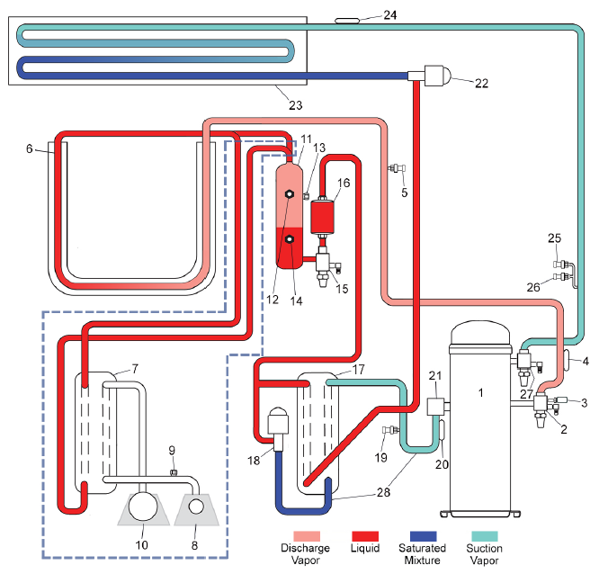
Note: Objects outlined by dashed lines (---) indicate an optional water cooled condenser installed.
1)Compressor
2)Discharge Service Valve
3)High Pressure Switch (HPS)
4)Discharge Temperature Sensor (CPDS)
5)Discharge Pressure Transducer (DPT)
6)Condenser Coil and Fan
7)Water-Cooled Condenser [optional]
8)Coupling, Water In [optional]
9)Water Pressure Switch [optional]
10)Coupling, Water Out [optional]
11)Receiver
12)Receiver Sight Glass
13)Fusible Plug
14)Receiver Liquid Level / Moisture Indicator
15)Liquid Line Service Valve
16)Filter Drier
17)Economizer
18)Economizer Expansion Valve (ECV)
19)Economizer Pressure Transducer (ECP)
20)Economizer Temperature Sensor (ECT)
21)Economizer Connection
22)Electronic Expansion Valve (EEV)
23)Evaporator Coil and Fan
24)Evaporator Temperature Sensor (ETS1 / ETS2)
25)Evaporator Pressure Transducer (EPT)
26)Suction Pressure Transducer (SPT)
27)Suction Service Valve
28)Flow of refrigerant back to compressor when Economized mode is active (ECV is energized)
- - - - -
Figure 3.37 Refrigeration Circuit Diagram, 701-100 to 149 Models
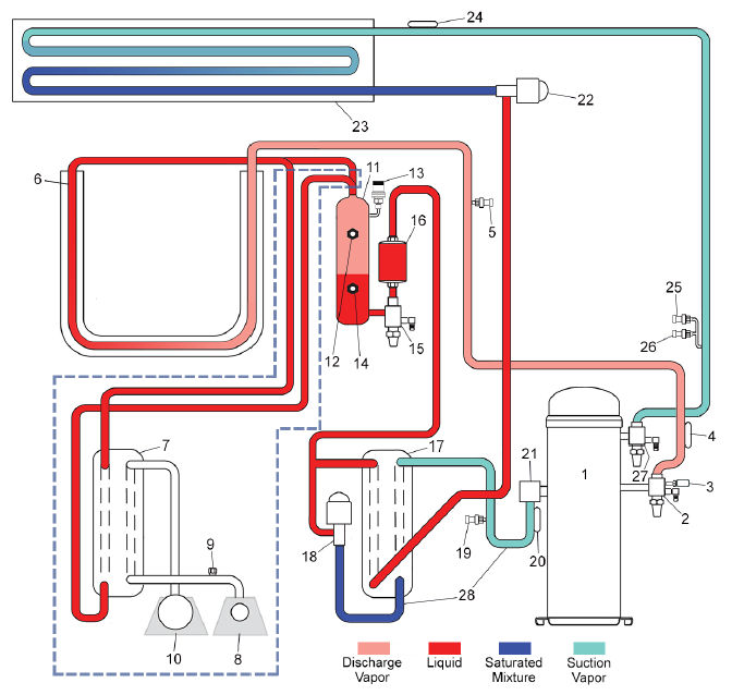
Note: Objects outlined by dashed lines (---) indicate an optional water cooled condenser installed.
1)Compressor
2)Discharge Service Valve
3)High Pressure Switch (HPS)
4)Discharge Temperature Sensor (CPDS)
5)Discharge Pressure Transducer (DPT)
6)Condenser Coil and Fan
7)Water-Cooled Condenser [optional]
8)Coupling, Water In [optional]
9)Water Pressure Switch [optional]
10)Coupling, Water Out [optional]
11)Receiver
12)Receiver Sight Glass
13)Pressure Relief Valve (PRV)
14)Receiver Liquid Level / Moisture Indicator
15)Liquid Line Service Valve
16)Filter Drier
17)Economizer
18)Economizer Expansion Valve (ECV)
19)Economizer Pressure Transducer (ECP)
20)Economizer Temperature Sensor (ECT)
21)Economizer Connection
22)Electronic Expansion Valve (EEV)
23)Evaporator Coil and Fan
24)Evaporator Temperature Sensor (ETS1 / ETS2)
25)Evaporator Pressure Transducer (EPT)
26)Suction Pressure Transducer (SPT)
27)Suction Service Valve
28)Flow of refrigerant back to compressor when Economized mode is active (ECV is energized)
- - - - -