Troubleshooting
NOTE: Read the Safety chapter carefully prior to troubleshooting the engine or generator set.
Prior to performing any failure diagnosis work, it is recommended to check and record the content of the Engine Pre-Work Checklist in order to check the engine’s state of use.
The Kubota Engine Park (KEP) website provides access to additional resources for operating, servicing and troubleshooting Kubota engines. From here, a user can download Diagmaster diagnosis software, application manuals, and service manuals. Contact a Carrier service engineer to request login credentials.
KEP can be accessed by visiting https://ba.engine.kubota.com/web/guest/home
The engine diagnosis procedures in this section involve connecting a computer to the engine ECU and using Diagmaster software to check engine conditions and measurements. Refer to the Diagmaster chapter for detailed installation and operating procedures.
5.3Symptom - Engine is Starting Poorly
The following symptoms may indicate an engine starting poorly:
•Engine can not start cranking
•Engine cranks, but fails to start
•Engine takes time to start
Table 5–1 Engine is Starting Poorly - Causes and Actions
|
Electrical System |
|
Cause / Action: 1.Power supply is poor. Check the battery. 2.Power supply circuit malfunction. Check the ignition switch or main relay. 3.Starting circuit malfunction. Check the starter, starter relay or ignition switch. 4.Preheating circuit malfunction. Check the glow relay or glow plug. |
|
Engine Body |
|
Cause / Action: 1.Engine is seizing. Check the crankshaft, piston or connecting rod. 2.Compression is insufficient. Check the cylinder, piston ring, valve, cylinder head, timing gear, or valve clearance. |
|
Fuel System |
|
Cause / Action: 1.Fuel supply is poor. Check the fuel tank, fuel feed pumps, fuel filter or fuel hoses. 2.Fuel high pressure supply is poor. Check the supply pump, suction control valve (SCV) or rail. 3.Fuel injection is poor. Check the injector or overflow pipe. 4.Sensor signal problem. Check the crankshaft position sensor, camshaft position sensor or pulsar gear. 5.Fuel is poor. Check the fuel quality. |
|
Intake / Exhaust System |
|
Cause / Action: 1.Intake is poor. Check the air cleaner. 2.Exhaust is poor. Check the DOC. |
|
Other |
|
Cause / Action: 1.Operating environment problem. Check for cold outside temperatures. 2.Problem on vehicle side. Check the engine drag or start conditions. 3.ECU stop instruction. Check the ECU or engine stop switch. |
5.3.1Diagnosing an Engine that is Starting Poorly
1.Inspect the following items (from the pre-work checklist, Section 6.2) to verify the following criteria:
•Fuel quantity meets the specified amount; Fuel quality meets the fuel standard
•Air cleaner element is not clogged
2.Connect a computer to the ECU and open Diagmaster software.
3.Place the ignition switch (IGN) in the START position to start the engine.
4.If the engine starts, then continue to the next step. If the engine does not start, check the following:
•The battery is causing a power supply problem.
•The ignition switch or main relay is causing a malfunction in the power supply circuit.
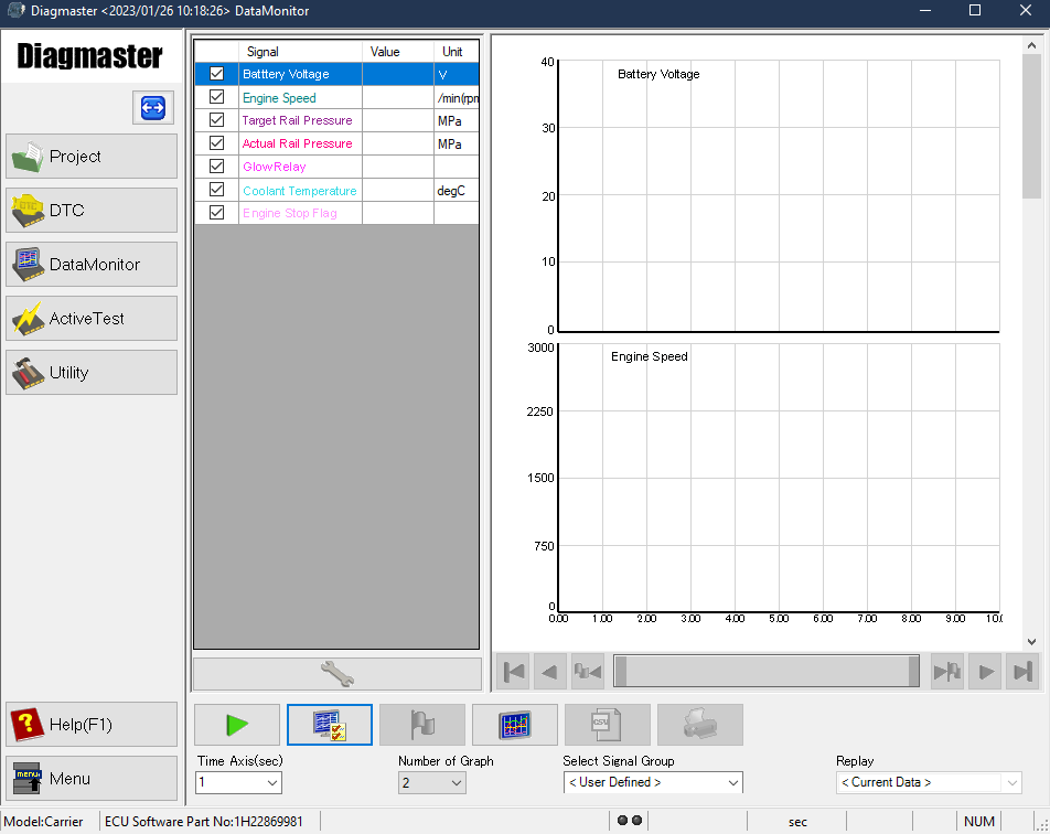
5.Go to the Data Monitor screen and bring up the following data monitor settings on the screen.
•Battery Voltage, Engine Speed, Target Rail Pressure and Actual Rail Pressure, Glow Relay, Coolant Temperature, Engine Stop Flag
6.Click the Play button (green) to start data measurement and Stop button (gray) to finish. During a measurement, observe the data on screen when the engine is stopped (ignition RUN) and also when the engine cranking (ignition START). Check the measurements for each of the settings active in the screen and compare to the reference values given in the tables below.
If the problem can not be solved after observing the measurements, check the compression pressure measurement. If compression is insufficient: check the cylinder, piston ring, valve, cylinder head, timing gear or valve clearance.
|
Battery Voltage |
|
|
Reference: |
When engine stopped (ignition RUN): around 12V When engine cranking: 10 to 12V |
|
Symptom: |
Voltage is too low when ignition is in RUN or while cranking. |
|
Cause / Action: |
Power supply is poor. Check the battery. |
|
Engine Speed |
|
|
Reference: |
When engine stopped (ignition RUN): 0 rpm When engine cranking: 200 rpm |
|
Symptom: |
No rotation |
|
Cause / Action: |
Starting circuit malfunction. Check the starter, starter relay, or ignition switch |
|
Symptom: |
Slow rotation |
|
Cause / Action: |
Engine seizing. Check the crankshaft, piston, or connecting rod |
|
Target Rail Pressure vs Actual Rail Pressure |
|
|
Reference: |
When engine stopped (ignition RUN): Target __ MPa, Actual 0 MPa When engine cranking: Equivalent to target |
|
Symptom: |
Actual rail pressure is higher than the target |
|
Cause / Action: |
Fuel injection is poor. Check the injector or overflow pipe |
|
Symptom: |
Actual pressure is lower than the target |
|
Cause / Action: |
Fuel high pressure supply is poor. Check the high pressure supply pump, suction control valve (SCV), rail, or injector. |
|
Cause / Action: |
Fuel supply is poor. Check the fuel tank, fuel feed pumps, fuel filter, or fuel hoses. |
|
Glow Relay | Coolant Temperature |
|
|
Reference: |
OFF: Coolant temperature 21°C or higher ON: Coolant temperature below 21°C. |
|
Symptom: |
Somewhat hotter than the glow relay operating temperature |
|
Cause / Action: |
Operating environment problem. Check for cold outside temperatures. |
|
Symptom: |
ON (operating) |
|
Cause / Action: |
Preheating circuit problem. Check the glow relay or glow plug. |
|
Engine Stop Flag |
|
|
Reference: |
When engine stopped (ignition RUN): ON When engine cranking: OFF |
|
Symptom: |
Stays ON even after cranking |
|
Cause / Action: |
ECU stop instruction. Check the engine stop switch or ECU. |
Other Related Procedures:
•Check the Fuel System. See Section 6.4.1.
•Check the Intake Air System. See Section 6.4.2.
•Check the Electrical System.
5.4Symptom - Engine is Operating Poorly
The following symptoms may indicate an engine operating poorly:
•Engine idle is unstable
•Engine response is slow or no response
•Engine stalls
Table 5–2 Engine is Operating Poorly - Causes and Actions
|
Engine Body |
|
Cause / Action: 1.Compression is insufficient. Check the cylinder, piston ring, valve, cylinder head, timing gear, or valve clearance. |
|
Fuel System |
|
Cause / Action: 1.Fuel supply is poor. Check the fuel tank, fuel feed pumps, fuel filter or fuel hoses. 2.Fuel high pressure supply is poor. Check the high pressure supply pump, suction control valve (SCV) or rail. 3.Fuel injection is poor. Check the injector. 4.Sensor signal problem. Check the crankshaft position sensor, camshaft position sensor, pulsar gear, rail pressure sensor, coolant temperature sensor, or CAN communications. 5.Fuel is poor. Check the fuel quality. |
|
Intake / Exhaust System |
|
Cause / Action: 1.Intake is poor. Check the air cleaner or intake air hose. 2.Exhaust is poor. Check the DOC. |
|
Other |
|
Cause / Action: 1.Problem on vehicle side. Check for overload or CAN communication content. 2.Calibration or correction after maintenance was not completed. Check that an injector correction or injection timing correction was performed. |
5.4.1Diagnosing an Engine that is Operating Poorly
1.Inspect the following items (from the pre-work checklist, Section 6.2) to verify the following criteria:
•Engine oil quantity meets the specified amount; Engine oil quality meets the oil standard
•Fuel quantity meets the specified amount; Fuel quality meets the fuel standard
•Coolant quantity meets the specified amount
•Air cleaner element is not clogged.
2.Connect a computer to the ECU and open Diagmaster software.
3.Place the ignition switch (IGN) in the START position to start the engine.
4.Check that any of the procedures listed below were completed recently:
•Injector correction to an injector, or the engine ECU
•Injector timing correction to the flywheel housing, flywheel, or crankshaft
If so, verify that an Injector Compensation was performed on the Utility screen. This is necessary to re-register the injectors to the engine ECU. See Section 7.3.9 for related information.
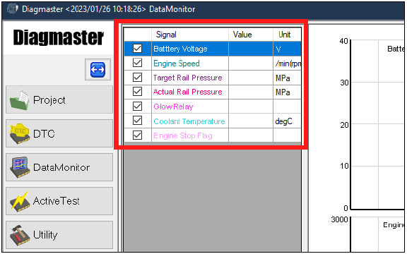
5.Go to the Data Monitor screen and bring up the following data monitor settings on the screen.
•Engine Speed, Target Rail Pressure and Actual Rail Pressure, Final Fuel Injection Quality
6.Click the Play button (green) to start data measurement and Stop button (gray) to finish. During a measurement, observe the data on screen when the engine is stopped (ignition RUN) and also when the engine cranking (ignition START). Check the measurements for each of the settings active in the screen and compare to the reference values given in the tables below.
If the problem can not be solved after observing the measurements, check the compression pressure measurement. If compression is insufficient: check the cylinder, piston ring, valve, cylinder head, timing gear or valve clearance.
|
Engine Speed: |
|
|
Reference: |
1500 rpm (at no-load maximum speed) |
|
Symptom: |
Engine reaches the specified rpm |
|
Cause / Action: |
Problem on generator side. Check for overload condition. |
|
Target Rail Pressure & Actual Rail Pressure: |
|
|
Reference: |
Equivalent to target (at no-load maximum speed) |
|
Symptom: |
Actual pressure equivalent to target pressure; Actual pressure follows the target pressure; Actual pressure is stable |
|
Cause / Action: |
Fuel pressure supply is poor. Check the supply pump, suction control valve (SCV), rail, or injector |
|
Cause / Action: |
Fuel supply is poor. Check the fuel tank, fuel feed pumps, fuel filter or fuel hoses. |
|
Cause / Action: |
Pressure sensor signal. Check the rail pressure sensor. |
|
Final Fuel Injection Quantity: |
|
|
Reference: |
About 90 MPa (at no-load maximum speed) |
|
Symptom: |
Quantity is too much |
|
Cause / Action: |
Fuel injection is poor. Check the injector. |
Other Related Procedures:
•Stop Injection of the Injector. See Section 7.3.8.
•Check the Fuel System. See Section 6.4.1.
•Check the Intake Air System. See Section 6.4.2.
•Check the Electrical System.
•Check the Coolant System. See Section 6.4.4.
5.5Symptom - Engine Output is Insufficient
The following symptoms may indicate an engine with insufficient output:
•Poor power
•Huge drop in RPM when under load
Table 5–3 Engine Output is Insufficient - Causes and Actions
|
Engine Body |
|
Cause / Action: 1.Compression is insufficient. Check the cylinder, piston ring, valve, cylinder head, timing gear, or valve clearance. |
|
Fuel System |
|
Cause / Action: 1.Fuel supply is poor. Check the fuel tank, fuel feed pumps, fuel filter or fuel hose. 2.Fuel high pressure supply is poor. Check the high pressure supply pump, suction control valve (SCV) or rail. 3.Fuel injection is poor. Check the injector. 4.Sensor signal problem. Check the crankshaft position sensor, camshaft position sensor, pulsar gear, rail pressure sensor, coolant temperature sensor, or CAN communications. 5.Fuel is poor. Check the fuel quality. |
|
Intake / Exhaust System |
|
Cause / Action: 1.Intake is poor. Check the air cleaner or intake air hose. 2.Exhaust is poor. Check the DOC. |
|
Lubrication System |
|
Cause / Action: 1.Oil viscosity is improper. Check the engine oil. 2.Oil quantity is excessive. Check the engine oil. |
|
Cooling System |
|
Cause / Action: 1.Coolant temperature rise is insufficient. Check the thermostat, coolant temperature sensor. 2.Overheating. Check the radiator, radiator cap, fan belt, fan drive, thermostat, water hose or coolant. |
|
Other |
|
Cause / Action: 1.Problem on vehicle side. Check for an overload or CAN communication error. 2.Calibration or correction after maintenance was not completed. Check that an injector correction or injection timing compensation was performed. 3.Operating environment problem. Check for hot or cold outside air or condition due to high altitude. |
5.5.1Diagnosing an Engine with Insufficient Output
1.Inspect the following items (from the pre-work checklist, Section 6.2) to verify the following criteria:
•Engine oil quantity meets the specified amount; Engine oil quality meets the oil standard
•Fuel quantity meets the specified amount; Fuel quality meets the fuel standard
•Fuel filter not clogged
•Coolant quantity meets the specified amount
•Air cleaner element is not clogged.
•Intake air hoses are not disconnected, have cracks or deformation
2.Connect a computer to the ECU and open Diagmaster software.
3.Place the ignition switch (IGN) in the START position to start the engine.
4.Check that any of the procedures listed below were completed recently:
•Injector correction to an injector, or the engine ECU
•Injector timing correction to the flywheel housing, flywheel, or crankshaft
If so, verify that an Injector Compensation was performed on the Utility screen. This is necessary to re-register the injectors to the engine ECU. See Section 7.3.9 for related information.
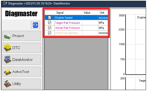
5.Go to the Data Monitor screen and bring up the following data monitor settings on the screen.
•Engine Speed, Target Rail Pressure & Actual Rail Pressure, Final Fuel Injection Quantity, Coolant Temperature, Atmospheric Pressure
6.Click the Play button (green) to start data measurement and Stop button (gray) to finish. During a measurement, observe the data on screen when the engine is stopped (ignition RUN) and also when the engine cranking (ignition START). Check the measurements for each of the settings active in the screen and compare to the reference values given in the tables below.
If the problem can not be solved after observing the measurements, check the compression pressure measurement. If compression is insufficient: check the cylinder, piston ring, valve, cylinder head, timing gear or valve clearance.
|
Engine Speed: |
|
|
Reference: |
1500 rpm (at no-load maximum speed) |
|
Symptom: |
It reaches the specified rpm. |
|
Cause / Action: |
Problem on vehicle side. Check for an overload condition. |
|
Target Rail Pressure & Actual Rail Pressure: |
|
|
Reference: |
Equivalent to target (at no-load maximum speed) |
|
Symptom: |
Actual pressure equivalent to target pressure; Actual pressure follows the target pressure; Actual pressure is stable |
|
Cause / Action: |
Fuel pressure supply is poor. Check the supply pump, suction control valve (SCV), rail, or injector. |
|
Fuel supply is poor. Check the fuel tank, fuel feed pumps, fuel filter, or fuel hoses. |
|
|
Pressure sensor signal. Check the rail pressure sensor |
|
|
Final Fuel Injection Quantity: |
|
|
Reference: |
About 90 MPa (at no-load maximum speed) |
|
Symptom: |
Quantity is too much |
|
Cause / Action: |
Fuel injection is poor. Check the injector. |
|
Coolant Temperature: |
|
|
Reference: |
After warmup, 80.5 to 95°C (At no-load maximum speed) |
|
Symptom: |
Temperature is too low |
|
Cause / Action: |
Coolant temperature rise is insufficient. Check the thermostat. |
|
|
Sensor signal error. Check the coolant temperature sensor. |
|
|
Operating environment problem. Check for cold outside air. |
|
Symptom: |
Temperature is too high |
|
Cause / Action: |
Overheating. Check the radiator, radiator cap, fan belt, fan drive or thermostat. |
|
|
Pressure sensor signal. Check the coolant temperature sensor. |
|
Atmospheric Pressure: |
|
|
Reference: |
About 100 kPa (At no-load maximum speed) |
|
Symptom |
Pressure is too low |
|
Cause / Action: |
Operating environment problem. Check for high altitude condition. |
Other Related Procedures:
•Stop Injection of the Injector. See Section 7.3.8.
•Check the Fuel System. See Section 6.4.1 for procedures.
•Check the Intake Air System. See Section 6.4.2 for procedures.
•Check the Electrical System.
•Check the Coolant System. See Section 6.4.4 for procedure.
5.6Symptom - Engine Noise is Abnormal
The following symptoms may indicate an engine with abnormal noise:
•Knocking
•Noise
Table 5–4 Engine Noise is Abnormal - Causes and Actions
|
Engine Body |
|
Cause / Action: 1.Compression leakage. Check the cylinder, piston ring, valve, cylinder head, timing gear, or valve clearance. |
|
Fuel System |
|
Cause / Action: 1.Fuel high pressure supply is poor. Check the high pressure supply pump, suction control valve (SCV) or rail. 2.Fuel injection is poor. Check the injector. 3.Sensor signal problem. Check the crankshaft position sensor, camshaft position sensor, pulsar gear or rail pressure sensor. 4.Fuel is poor. Check the fuel quality. |
|
Intake / Exhaust System |
|
Cause / Action: 1.Intake is poor. Check the air cleaner or intake air hose. |
|
Cooling System |
|
Cause / Action: 1.Overheating. Check the radiator, radiator cap, fan belt, fan drive, thermostat, water hose or coolant |
|
Other |
|
Cause / Action: 1.Engine drag. Check the power transmission parts on the vehicle side. 2.Calibration or correction after maintenance was not completed. Check that an injector correction or injection timing compensation was performed. 3.Loose parts. Check each clamp and mounting screw. |
5.6.1Diagnosing an Engine with Abnormal Noise
1.Inspect the following items (from the pre-work checklist, Section 6.2) to verify the following criteria:
•Engine oil quantity meets the specified amount; Engine oil quality meets the oil standard
•Fuel quantity meets the specified amount; Fuel quality meets the fuel standard
•Coolant quantity meets the specified amount
•Air cleaner element is not clogged.
2.Connect a computer to the ECU and open Diagmaster software.
3.Place the ignition switch (IGN) in the START position to start the engine.
4.Check that any of the procedures listed below were completed recently:
•Injector correction to an injector, or the engine ECU
•Injector timing correction to the flywheel housing, flywheel, or crankshaft
If so, verify that an Injector Compensation was performed on the Utility screen. This is necessary to re-register the injectors to the engine ECU. See Section 7.3.9 for related information.
5.Go to the Data Monitor screen and bring up the following data monitor settings on the screen:
•Target Rail Pressure & Actual Rail Pressure, Coolant Temperature, Atmospheric Pressure

6.Click the Play button (green) to start data measurement and Stop button (gray) to finish. During a measurement, observe the data on screen when the engine is stopped (ignition RUN) and also when the engine cranking (ignition START). Check the measurements for each of the settings active in the screen and compare to the reference values given in the tables below.
If the problem can not be solved after observing the measurements, check the compression pressure measurement. If compression is insufficient: check the cylinder, piston ring, valve, cylinder head, timing gear or valve clearance.
|
Target Rail Pressure & Actual Rail Pressure: |
|
|
Reference: |
Equivalent to target (at no-load maximum speed) |
|
Symptom: |
Actual pressure equivalent to target pressure; Actual pressure follows the target pressure; Actual pressure is stable |
|
Cause / Action: |
Fuel delivery / injection is abnormal. Check the supply pump, suction control valve (SCV), rail or injector. |
|
Fuel supply is unstable. Check the fuel tank, fuel feed pumps, fuel filter or fuel hose. |
|
|
Sensor error. Check the rail pressure sensor. |
|
|
Coolant Temperature: |
|
|
Reference: |
After warmup, 80.5 to 95°C (At no-load maximum speed) |
|
Symptom |
Temperature is too low |
|
Cause / Action: |
Coolant temperature rise is insufficient. Check the thermostat. |
|
Sensor signal error. Check the coolant temperature sensor. |
|
|
Operating environment problem. Check for cold outside air. |
|
|
Symptom: |
Temperature is too high |
|
Cause / Action: |
Overheating. Check the radiator, radiator cap, fan belt, fan drive or thermostat. |
|
Pressure sensor signal. Check the coolant temperature sensor. |
|
|
Operating environment problem. Check for hot outside air. |
|
|
Atmospheric Pressure: |
|
|
Reference: |
About 100 kPa (At no-load maximum speed) |
|
Symptom: |
Pressure is too low |
|
Cause / Action: |
Operating environment problem. Check for high altitude condition. |
Other Related Procedures:
•Stop Injection of the Injector. See Section 7.3.8.
•Check the Fuel System. See Section 6.4.1.
•Check the Intake Air System. See Section 6.4.2.
•Check the Electrical System.
•Check the Coolant System. See Section 6.4.4.
5.7Symptom - Engine Emission Deterioration
The following symptoms may indicate an engine with emission deterioration:
•Black smoke
•White smoke
Table 5–5 Engine Emission Deterioration - Causes and Actions
|
Engine Body |
|
Cause / Action: 1.Compression leakage. Check the cylinder, piston ring, valve, cylinder head, timing gear, or valve clearance. 2.Oil rise. Check the cylinder or piston ring. 3.Oil drop. Check the valve, valve stem seal or cylinder head. |
|
Fuel System |
|
Cause / Action: 1.Fuel high pressure supply or injection is poor. Check the high pressure supply pump, suction control valve (SCV), rail or injector. 2.Sensor signal problem. Check the crankshaft position sensor, camshaft position sensor, pulsar gear, rail pressure sensor, atmospheric pressure sensor, coolant temperature sensor. 3.Fuel is poor. Check the fuel quality. |
|
Intake / Exhaust System |
|
Cause / Action: 1.Intake is poor. Check the air cleaner or intake air hose. 2.Exhaust is poor. Check the DOC. |
|
Lubrication System |
|
Cause / Action: 1.Oil quantity excessive. Check the engine oil. |
|
Cooling System |
|
Cause / Action: 1.Coolant temperature rise is insufficient. Check the thermostat, coolant temperature sensor, or low ambient temperature. 2.Overheating. Check the radiator, radiator cap, fan belt, fan drive, thermostat, water hose or coolant, |
|
Other |
|
Cause / Action: 1.Operating environment problem. Check the atmospheric pressure sensor, coolant temperature sensor. |
5.7.1Diagnosing an Engine with Emission Deterioration
1.Inspect the following items (from the pre-work checklist, Section 6.2) to verify the following criteria:
•Engine oil quantity meets the specified amount; Engine oil quality meets the oil standard
•Engine oil amount is decreasing short term and increasing in long term
•Fuel quantity meets the specified amount; Fuel quality meets the fuel standard.
•Coolant quantity meets the specified amount
•Air cleaner element is not clogged.
2.Connect a computer to the ECU and open Diagmaster software.
3.Place the ignition switch (IGN) in the START position to start the engine.
4.Check that any of the procedures listed below were completed recently:
•Injector correction to an injector, or the engine ECU
•Injector timing correction to the flywheel housing, flywheel, or crankshaft
If so, verify that an Injector Compensation was performed on the Utility screen. This is necessary to re-register the injectors to the engine ECU. See Section 7.3.9 for related information.
5.Go to the Data Monitor screen and bring up the following data monitor settings on the screen:
•Target Rail Pressure & Actual Rail Pressure, Coolant Temperature, Atmospheric Pressure
6.Click the Play button (green) to start data measurement and Stop button (gray) to finish. During a measurement, observe the data on screen when the engine is stopped (ignition RUN) and also when the engine cranking (ignition START). Check the measurements for each of the settings active in the screen and compare to the reference values given in the tables below.
If the problem can not be solved after observing the measurements, check the following items:
Check the compression pressure measurement. If compression is insufficient: check the cylinder, piston ring, valve, cylinder head, timing gear or valve clearance.
Check the cylinder wear and piston ring gap. If oil rise is observed: check the cylinder or piston ring.
Check the valve stems and cylinder head. If oil drop is observed: check the valve, valve stem seal or cylinder head.
|
Target Rail Pressure & Actual Rail Pressure: |
|
|
Reference: |
Equivalent to target (at no-load maximum speed) |
|
Symptom: |
Actual pressure equivalent to target pressure; Actual pressure follows the target pressure; Actual pressure is stable |
|
Cause / Action: |
Fuel delivery / injection is abnormal. Check the supply pump, suction control valve (SCV), rail or injector. |
|
Fuel supply is unstable. Check the fuel tank, pre-filter fuel pump, fuel filter, fuel feed pump or fuel hose. |
|
|
Sensor error. Check the rail pressure sensor |
|
|
Coolant Temperature: |
|
|
Reference: |
After warmup, 80.5 to 95°C (At no-load maximum speed) |
|
Symptom: |
Temperature is too low |
|
Cause / Action: |
Coolant temperature rise is insufficient. Check the fan drive. |
|
Sensor signal error. Check the coolant temperature sensor. |
|
|
Operating environment problem. Check for cold outside air condition. |
|
|
Symptom |
Temperature is too high |
|
Cause / Action: |
Overheating. Check the radiator, radiator cap, fan belt, fan drive or thermostat. |
|
Pressure sensor signal. Check the coolant temperature sensor. |
|
|
Operating environment problem. Check for hot outside air condition. |
|
|
Atmospheric Pressure: |
|
|
Reference: |
About 100 kPa (At no-load maximum speed) |
|
Symptom: |
Temperature is too low |
|
Cause / Action: |
Operating environment problem. Check for a high altitude condition. |
Other Related Procedures:
•Stop Injection of the Injector. See Section 7.3.8.
•Check the Fuel System. See Section 6.4.1.
•Check the Intake Air System. See Section 6.4.2.
•Check the Electrical System.
•Check the Coolant System. See Section 6.4.4.
5.8Battery Charger Troubleshooting
Table 5–6 Battery Charger - Causes and Actions
|
Condition: CB4 trips when charger is turned on. |
|
Cause / Action: 1.Short in 12-volt wiring causing overload of charger. Locate and remove short or replace the charger. |
|
Condition: Circuit breaker trips repeatedly, even when not connected. |
|
Cause / Action: 1.Internal short. Replace the charger. |
|
Condition: Charger does not taper back after charging for a few minutes. |
|
Cause / Action: 1.Bad cell in battery. Test battery for defect according to battery manufacturer’s instructions. 2.Charger is bad. Replace the charger. |
|
Condition: Charger does not charge. |
|
Cause / Action: 1.Fuse BCF3 is open. Replace the fuse. 2.Charger is not receiving AC input. Use voltmeter to confirm charger is receiving 360-500 VAC. If not, check input connections / fuses. 3.Charger output is not connected to 12 volt battery. Check output wiring connections to battery. 4.Charger is bad. Replace the charger. |
|
Condition: Low output voltage measured across charger output. |
|
Cause / Action: 1.Battery is not connected to the charger. It is normal to measure 12 volts or less across charger output with no battery connected. Check charging leads from the charger to the battery. |
|
Condition: Reverse polarity connection to battery has caused charger to stop charging. |
|
Cause / Action: 1.Internal DC fuse is blown and possible damage to current carrying components. Replace. |
5.9Alternating Current (AC) Generator Troubleshooting
Table 5–7 Alternating Current Generator - Causes and Actions
|
Condition: No voltage. |
|
Cause / Action: 1.Rotor magnetism is lost. Replace. 2.Circuit breaker is tripped. Check CB1. 3.Open in stator windings. Replace. 4.Short circuited. Replace. 5.Worn drive gear is stripped. Check / Replace. 6.Contactor is not engaged. Replace. |
|
Condition: Low voltage |
|
Cause / Action: 1.Engine speed is low. Refer to the Engine workshop manual. 2.High resistance connections, connections are warm or hot. Tighten. 3.Rotor magnetism is lost. Replace. |
|
Condition: Fluctuating voltage (May be indicated by flickering lights) |
|
Cause / Action: 1.Speed fluctuating. 2.Engine speed is irregular. Refer to the Engine workshop manual. 3.Terminal or load connections are loose. Tighten. 4.Bad bearing is causing uneven air gap. Replace. |
|
Condition: High Voltage |
|
Cause / Action: 1.Engine speed is excessive |
|
Condition: Overheating |
|
Cause / Action: 1.Generator is overloaded. Check. 2.Vents / baffles are clogged. Check / clean. 3.High temperature surrounding generator. 4.Air circulation or recirculation is insufficient. Check / clean. 5.Load is unbalanced. 6.Bearing is dry. Replace. |
|
Condition: Mechanical Noise |
|
Cause / Action: 1.Bearing is bad. Replace. 2.Rotor is rubbing on stator. Replace. 3.Laminations are loose. Replace. 4.Coupling is loose or misaligned. Check drive gear. |
|
Condition: Generator frame produces shock when touched. |
|
Cause / Action: 1.Static charge. Check ground to frame. |
5.10Voltage Controller Troubleshooting
The voltage controller has one green indicator light and one yellow indicator light. When the green light is illuminated, it means that the voltage controller is receiving power. The yellow light only illuminates (flashes) to indicate that there is a problem.
Table 5–8 Voltage Controller - Causes and Actions
|
Condition: Green LED is not illuminated. |
|
Cause / Action: 1.No power to the voltage controller (VC). Contactor failed. Or, check line side power on contactors. |
|
Condition: Yellow LED flash code: one long and three short |
|
Cause / Action: 1.Over voltage error. Check engine speed. |
|
Condition: Yellow LED flash code: one long and four short |
|
Cause / Action: 1.Under voltage error. Check engine speed. |
5.11High Voltage Circuit, Electrical Troubleshooting
Before proceeding with troubleshooting, make sure to follow your company’s standard safety procedures for working with electrical components.
Table 5–9 High Voltage Circuit Troubleshooting
|
Item: Receptacle (R) |
|
Checks / Cause / Action: 1.Check output voltage at Receptacle R (L1-L2, L2-L3, L1-L3) (50Hz: 360 - 460 VAC and 60Hz: 400 - 500 VAC). Problem could be a faulty receptacle. Replace. |
|
Item: High Voltage Wires (from Circuit Breaker to Receptacle) |
|
Checks / Cause / Action: 1.Check if wires / terminals are connected. Check continuity for each leg. Problem could be loose connections. Tighten as required. |
|
Item: Circuit Breaker (CB) |
|
Checks / Cause / Action: 1.Test the output power from circuit breaker CB (21-22, 22-23, 21-23). Problem could be a faulty circuit breaker. Replace. 2.Verify circuit breaker (CB) is in the ON position. 3.Test the input power to the circuit breaker CB (11-12, 12-13, 11-13). |
|
Item: Voltage Controller (VC) and Fuses |
|
Checks / Cause / Action: 1.Verify VCF1 fuse is not blown. Check continuity for each leg across fuse, outside of circuit; inside of circuit if not running. Replace fuse if required. 2.Verify VCF2 fuse is not blown. Check continuity for each leg across fuse, outside of circuit; inside of circuit if not running. Replace fuse if required. 3.Verify voltage controller has power (powered by high voltage). Verify green light is illuminated. Problem could be a faulty voltage controller, loose connections or a faulty generator. |
|
Item: Voltage Controller (VC) and Fuses |
|
4.Verify voltage controller has green light illuminated and yellow light flashing at 1 Hz. Yellow light flashing sequence other than at 1 Hz indicates a fault condition. •One Long / Two Short = voltage controller fault. This indicates a failed voltage controller. Replace. •One Long / Three Short = over voltage error. Check engine speed. •One Long / Four Short = under voltage error. Check engine speed. •One Long / Five Short = hot start error. Reset power to the unit. •One Long / Six Short = voltage controller fault. This indicates a failed voltage controller. Replace. •One Long / Seven Short = voltage controller fault. This indicates a failed voltage controller. Replace 5.Verify that the connectors to the Voltage Controller are secured; snapped in place and do not easily pull out. Check if the connectors are pushed in all the way. Remove connectors and inspect terminal pin insertion depth. Very depth is the same. Check to see if wires / terminals are connected. |
5.12DTC Codes
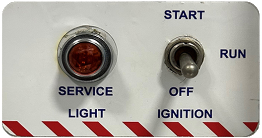
When an error occurs in the engine control unit (ECU), the engine service light on the generator set control panel illuminates to signal that a DTC code is present.
Figure 5.1 Engine Service Light (ESL)
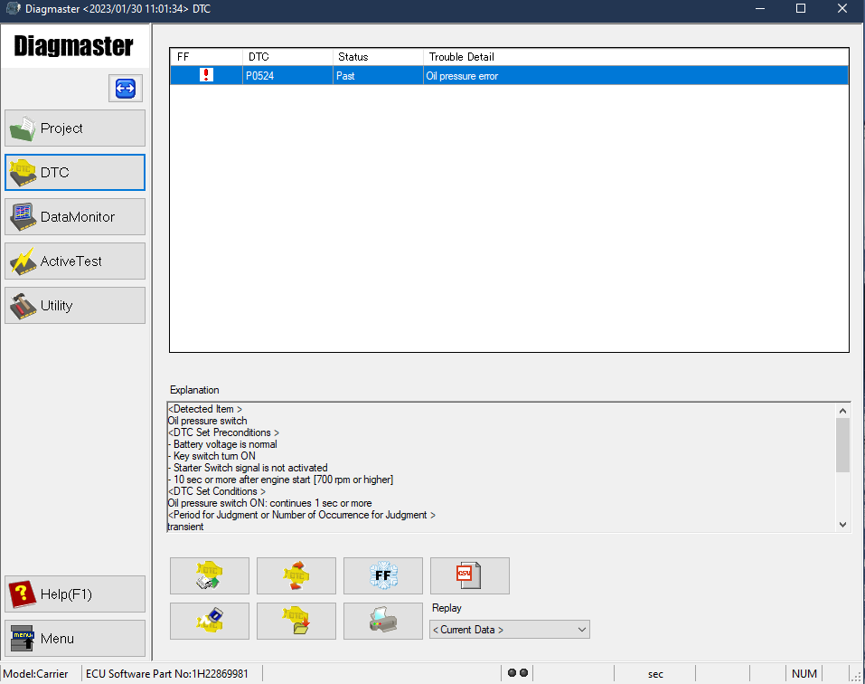
DTC codes can be monitored by connecting a computer to the ECU and using Diagmaster software. Diagmaster has a DTC screen that allows for managing of DTC codes, including saving code information and clearing codes. Refer to the Section 7.2 for Diagmaster installation and operation procedures.
Figure 5.2 Diagmaster DTC Screen
5.12.1P0016 NE-G phase shift (636-7)
|
SPN Name: |
Engine Position Sensor |
|
Cause: |
A large phase shift occurs between NE pulse and G pulse. NE refers to the crankshaft position sensor (Engine speed sensor) G refers to the camshaft position sensor |
|
DTC set preconditions: |
•Ignition switch is ON •Battery voltage is normal •Sensor supply voltage VCC# is normal •NE sensor signal is normal •G sensor signal is normal •Engine speed is 350 rpm or higher •Coolant temperature is 10°C (50°F) or higher |
|
DTC set parameter: |
The phase difference between NE pulse and G pulse is approximately within +30 and -20 degrees. |
|
Time to action / number of error detections: |
2 times or more |
|
Limp home action: |
There is an output limitation of approximately 75% of normal condition. |
|
Behavior during malfunction: |
The engine hesitates at start-up due to an invalid G sensor signal. |
|
Error recovery conditions: |
Diagnostic counter = 0 or turn ignition switch OFF |
|
Delay time for recovery: |
Delay time varies with engine speed in proportional relation: 30 seconds at 800 rpm, 15 seconds at 1600 rpm. |
|
Components to check: |
•Pulsar gear of the camshaft position sensor •Flywheel •Cam gear •Crank gear •Camshaft •Crankshaft •Wire harness |
Related Reference Material
•Description and location of engine position sensors (NE and G). See Section 3.7.9.
•Inspect around the pulsar hole on flywheel. See Section 5.13.1.
•Inspect around the camshaft position pulsar gear. See Section 5.13.2.
5.12.2P0087 Pressure limiter emergency open (633-7)
|
SPN Name: |
Engine Fuel Actuator 1 Control Command |
|
Cause: |
Pressure limiter emergency is open |
|
DTC set preconditions: |
Sensor supply voltage VCC# is normal |
|
DTC set parameter: |
•Pressure limiter emergency is open •Engine speed is more than 10 rpm |
|
Time to action / number of error detections: |
One time or more |
|
Limp home action: |
There is an output limitation of approximately 50% of normal condition. |
|
Behavior during malfunction: |
•Output is insufficient •Exhaust gas emissions will worsen |
|
Error recovery conditions: |
Turn ignition switch OFF. |
|
Delay time for recovery: |
None |
|
Components to check: |
•Fuel •Fuel hose •SCV •Supply pump •Rail (rail pressure sensor) •Injector |
|
Remarks |
This code is to minimize PM emission. Engine speed may go down due to lack of fuel pressure, regardless limp home action. |
Related Reference Material
•Description of fuel system. See Section 3.7.
•Diagnosing fuel pressure (low / high) or a stuck SCV. See Section 5.13.3.
5.12.3P0088 High rail pressure (157-0)
|
SPN Name: |
Engine Injector Metering Rail 1 Pressure |
|
Cause: |
Actual pressure exceeds the command pressure |
|
DTC set preconditions: |
•Rail pressure sensor is normal •Sensor supply voltage VCC# is normal |
|
DTC set parameter: |
Actual pressure is more than 179 MPa (1830 kg/cm2, 26000 psi) |
|
Time to action / number of error detections: |
3 seconds or more |
|
Limp home action: |
There is an output limitation of approximately 50% of normal condition. |
|
Behavior during malfunction: |
•Output is insufficient •Exhaust gas emissions will worsen |
|
Error recovery conditions: |
Turn ignition switch OFF. |
|
Delay time for recovery: |
None |
|
Components to check: |
•Fuel •Fuel hose •SCV •Supply pump •Rail (rail pressure sensor) •Injector |
|
Remarks |
This code is to minimize PM emission. |
Related Reference Material
•Description of fuel system. See Section 3.7.
•Location of rail pressure sensor. See Section 3.7.9.
•Diagnosing fuel pressure (low / high) or a stuck SCV. See Section 5.13.3.
5.12.4P0089 SCV stuck (1347-7)
|
SPN Name: |
Engine Fuel Pump Pressurizing Assembly #1 |
|
Cause: |
Suction control valve (SCV) is stuck at the open position. Actual rail pressure continuously exceeds the command rail pressure. |
|
DTC set preconditions: |
•Engine is running (Q: 3 mm3/st or more) •Injector is normal •Battery voltage is normal •Sensor supply voltage VCC# is normal •Rail pressure sensor is normal |
|
DTC set parameter: |
Discharge request of supply pump goes -1800 mm3/st or less and the actual rail pressure is 20 MPa (200 kgf/cm2, 2900 psi) higher than command pressure. |
|
Time to action / number of error detections: |
5 seconds or more |
|
Limp home action: |
There is an output limitation of approximately 50% of normal condition. |
|
Behavior during malfunction: |
•Output is insufficient •Exhaust gas emissions will worsen •Engine stops in some cases |
|
Error recovery conditions: |
Turn ignition switch OFF. |
|
Delay time for recovery: |
None |
|
Components to check: |
•Fuel •Fuel hose •SCV •Supply pump •Rail (rail pressure sensor) •Injector |
|
Remarks |
This code is to minimize PM emission. |
Related Reference Material
•Description of fuel system. See Section 3.7.
•Location of SCV. See Section 3.7.9.
•Diagnosing fuel pressure (low / high) or a stuck SCV. See Section 5.13.3.
5.12.5P0093 Fuel leak high pressure fuel system (1239-1)
|
SPN Name: |
Engine Fuel Leakage 1 |
|
Cause: |
Fuel leak from the high pressure fuel system. Fuel consumption is calculated from the difference of fuel pressure before and after the injection. And the error will be detected when excess fuel consumption is found. |
|
DTC set preconditions: |
•Battery voltage is normal •Sensor supply voltage VCC# is normal •Rail pressure sensor is normal •Suction control valve (SCV) is normal •Injector and injector drive circuit are normal •Crankshaft position sensor (NE) signal is active. Engine is operating at 700 rpm or more. •No DTC of P0087, P0088, P0089 |
|
DTC set parameter: |
•Pump supplies fuel fully •The deviation between actual rail pressure and desired one is more than 20 MPa (200 kg/cm2, 2900 psi) |
|
Time to action / number of error detections: |
60 seconds or more |
|
Limp home action: |
There is an output limitation of approximately 50% of normal condition. |
|
Behavior during malfunction: |
•Output is insufficient •Exhaust gas emissions will worsen •Engine stops in some cases |
|
Error recovery conditions: |
Turn ignition switch OFF. |
|
Delay time for recovery: |
None |
|
Components to check: |
•Fuel •Fuel system-related parts |
|
Remarks |
This code is to minimize PM emission |
Related Reference Material
•Description of fuel system. See Section 3.7.
•Diagnosing low fuel pressure in the high pressure system. See Section 5.13.4.
5.12.6P0117 Coolant temperature sensor: low (110-4)
|
SPN Name: |
Engine Coolant Temperature |
|
Cause: |
Ground short circuit of the coolant temperature sensor or harness. |
|
DTC set preconditions: |
Battery voltage is normal |
|
DTC set parameter: |
Voltage of the coolant temperature sensor is 0.176 V or less. |
|
Time to action / number of error detections: |
3 seconds or more |
|
Limp home action: |
•During start-up = -25°C (-13°F) [default value] •Under other conditions = 80°C (176°F) [default value] •There is an output limitation of approximately 75% of normal condition. |
|
Behavior during malfunction: |
•Increase in amount of white smoke at low temperature •Output is insufficient •Exhaust gas emissions will worsen |
|
Error recovery conditions: |
Turn ignition switch OFF. |
|
Delay time for recovery: |
None |
|
Components to check: |
•Coolant temperature sensor •Wire harness •ECU |
Related Reference Material
•Description of coolant system. See Section 3.10.
•Location of coolant temperature sensor. See Section 3.7.9
•Checking coolant temperature sensor, wire harness, ECU connectors. See Section 5.13.5.
5.12.7P0118 Coolant temperature sensor: high (110-3)
|
SPN Name: |
Engine Coolant Temperature |
|
Cause: |
Open circuit or +B short circuit of the coolant temperature sensor or harness. |
|
DTC set preconditions: |
Battery voltage is normal |
|
DTC set parameter: |
Voltage of the coolant temperature sensor is 4.87 V or more. |
|
Time to action / number of error detections: |
3 seconds or more |
|
Limp home action: |
•During start-up = -25°C (-13°F). This is the default value. •Under other conditions = 80°C (176°F). This is the default value. •There is an output limitation of approximately 75% of normal condition. |
|
Behavior during malfunction: |
•White smoke increases at low temperature •Output is insufficient •Exhaust gas emissions will worsen |
|
Error recovery conditions: |
Turn ignition switch OFF. |
|
Delay time for recovery: |
None |
|
Components to check: |
•Coolant temperature sensor •Wire harness •ECU |
Related Reference Material
•Description of coolant system. See Section 3.10.
•Location of coolant temperature sensor. See Section 3.7.9.
•Checking coolant temperature sensor, wire harness, ECU connectors. See Section 5.13.6.
5.12.8P0192 Rail pressure sensor: low (157-4)
|
SPN Name: |
Engine Injector Metering Rail 1 Pressure |
|
Cause: |
Ground short circuit of the rail pressure sensor or harness. Or, the rail pressure sensor has failed. |
|
DTC set preconditions: |
•Battery voltage is normal •Sensor supply voltage VCC# is normal |
|
DTC set parameter: |
Voltage of the rail pressure sensor is 0.065 V or less. |
|
Time to action / number of error detections: |
Transient |
|
Limp home action: |
There is an output limitation of approximately 50% of normal condition. And the engine is forcibly stopped 60 seconds later. |
|
Behavior during malfunction: |
•Output is insufficient •Exhaust gas emissions will worsen •Noise will worsen •White smoke increases •Engine stops |
|
Error recovery conditions: |
Turn ignition switch OFF. |
|
Delay time for recovery: |
None |
|
Components to check: |
•Rail pressure sensor (rail) •Wire harness •ECU |
|
Remarks |
This code is to minimize PM emission |
Related Reference Material
•Description of fuel system. See Section 3.7.
•Location of rail pressure sensor. See Section 3.7.9.
•Measuring output voltage of the ECU connector - rail pressure sensor. See Section 5.13.10.
•Measuring output voltage - rail pressure sensor. See Section 5.13.11.
•Measuring power supply voltage - rail pressure sensor. See Section 5.13.12.
•Measuring power supply voltage of the ECU connectors - rail pressure sensor. See Section 5.13.13.
•Checking ECU connectors. See Section 5.13.47.
5.12.9P0193 Rail pressure sensor: high (157-3)
|
SPN Name: |
Engine Injector Metering Rail 1 Pressure |
|
Cause: |
•Open circuit or +B short circuit of the rail pressure sensor or harness. Or, the rail pressure sensor has failed. |
|
DTC set preconditions: |
•Battery voltage is normal •Sensor supply voltage VCC# is normal |
|
DTC set parameter: |
Voltage of rail pressure sensor is 3.235 V or more. |
|
Time to action / number of error detections: |
Transient |
|
Limp home action: |
There is an output limitation of approximately 50% of normal condition. And the engine is forcibly stopped 60 seconds later. |
|
Behavior during malfunction: |
•Output is insufficient •Exhaust gas emissions will worsen •Noise will worsen •White smoke increases •Engine stops |
|
Error recovery conditions: |
Turn ignition switch OFF. |
|
Delay time for recovery: |
None |
|
Components to check: |
•Rail pressure sensor (rail) •Wire harness •ECU |
|
Remarks |
This code is to minimize PM emission |
Related Reference Material
•Description of fuel system. See Section 3.7.
•Location of rail pressure sensor. See Section 3.7.9.
•Measuring output voltage of the ECU connector - rail pressure sensor. See Section 5.13.10.
•Measuring output voltage - rail pressure sensor. See Section 5.13.11.
•Measuring power supply voltage - rail pressure sensor. See Section 5.13.12.
•Measuring power supply voltage of the ECU connectors - rail pressure sensor. See Section 5.13.13.
•Checking ECU connectors. See Section 5.13.47.
•Checking injector driving circuit. See Section 5.13.14.
•Checking injectors. See Section 5.13.15.
5.12.10P0200 Injector charge voltage: high (523535-0)
|
SPN Name: |
proprietary |
|
Cause: |
Injector charge voltage is high. |
|
DTC set preconditions: |
•Battery voltage is normal •CPU is normal |
|
DTC set parameter: |
Injector charge voltage: High |
|
Time to action / number of error detections: |
Transient |
|
Limp home action: |
There is an output limitation of approximately 75% of normal condition. And the engine is forcibly stopped 60 seconds later. |
|
Behavior during malfunction: |
•Output is insufficient •Exhaust gas emissions will worsen •Engine stops |
|
Error recovery conditions: |
Turn ignition switch OFF. |
|
Delay time for recovery: |
None |
|
Components to check: |
•Injector •ECU |
Related Reference Material
•Checking injector driving circuit. See Section 5.13.14.
•Checking injectors. See Section 5.13.15.
5.12.11P0201 Open circuit of harness or coil in 1st cylinder injector (651-3)
|
SPN Name: |
Engine Injector Cylinder #01 |
|
Cause: |
Open circuit of either the harness or the injector coil. |
|
DTC set preconditions: |
•Engine is operating •Battery voltage is normal •Occurs during injection •CPU is normal |
|
DTC set parameter: |
Open circuit of either the harness or injector coil. |
|
Time to action / number of error detections: |
3 times or more |
|
Limp home action: |
There is an output limitation of approximately 75% of normal condition. |
|
Behavior during malfunction: |
•Output is insufficient •Exhaust gas emissions will worsen •Vibration increases |
|
Error recovery conditions: |
Turn ignition switch OFF. |
|
Delay time for recovery: |
None |
|
Components to check: |
•Injector •Wire harness •ECU |
|
Remarks |
This code is to minimize PM emission. Injectors which have no error continue to operate. |
Related Reference Material
•Location of injectors. See Section 3.7.9.
•Checking injectors. See Section 5.13.16.
•Checking wire harness for disconnection. See Section 5.13.17.
•Checking ECU connectors. See Section 5.13.47.
5.12.12P0202 Open circuit of harness or coil in 3rd cylinder injector (653-3)
|
SPN Name: |
Engine Injector Cylinder #03 |
|
Cause: |
Open circuit of either the harness or injector coil. |
|
DTC set preconditions: |
•Engine is operating •Battery voltage is normal •Occurs during injection •CPU is normal |
|
DTC set parameter: |
Open circuit of either the harness or injector coil. |
|
Time to action / number of error detections: |
3 times or more |
|
Limp home action: |
There is an output limitation of approximately 75% of normal condition. |
|
Behavior during malfunction: |
•Output is insufficient •Exhaust gas emissions will worsen •Vibration increases |
|
Error recovery conditions: |
Turn ignition switch OFF. |
|
Delay time for recovery: |
None |
|
Components to check: |
•Injector •Wire harness •ECU |
|
Remarks |
This code is to minimize PM emission. Injectors which have no error continue to operate. |
Related Reference Material
•Location of injectors. See Section 3.7.9.
•Checking injectors. See Section 5.13.16.
•Checking wire harness for disconnection. See Section 5.13.17.
•Checking ECU connectors. See Section 5.13.47.
5.12.13P0203 Open circuit of harness or coil in 4th cylinder injector (654-3)
|
SPN Name: |
Engine Injector Cylinder #04 |
|
Cause: |
Open circuit of either the harness or the injector coil. |
|
DTC set preconditions: |
•Engine is operating •Battery voltage is normal •Occurs during injection •CPU is normal |
|
DTC set parameter: |
Open circuit of either the harness or the injector coil. |
|
Time to action / number of error detections: |
3 times or more |
|
Limp home action: |
There is an output limitation of approximately 75% of normal condition. |
|
Behavior during malfunction: |
•Output is insufficient •Exhaust gas emissions will worsen •Vibration increases |
|
Error recovery conditions: |
Turn ignition switch OFF. |
|
Delay time for recovery: |
None |
|
Components to check: |
•Injector •Wire harness •ECU |
|
Remarks |
This code is to minimize PM emission. Injectors which have no error continue to operate. |
Related Reference Material
•Location of injectors. See Section 3.7.9.
•Checking injectors. See Section 5.13.16.
•Checking wire harness for disconnection. See Section 5.13.17.
•Checking ECU connectors. See Section 5.13.47.
5.12.14P0204 Open circuit of harness or coil in 2nd cylinder injector (652-3)
|
SPN Name: |
Engine Injector Cylinder #02 |
|
Cause: |
Open circuit of either the harness or the injector coil. |
|
DTC set preconditions: |
•Engine is operating •Battery voltage is normal •Occurs during injection •CPU is normal |
|
DTC set parameter: |
Open circuit of either the harness or the injector coil. |
|
Time to action / number of error detections: |
3 times or more |
|
Limp home action: |
There is an output limitation of approximately 75% of normal condition. |
|
Behavior during malfunction: |
•Output is insufficient •Exhaust gas emissions will worsen •Vibration increases |
|
Error recovery conditions: |
Turn ignition switch OFF. |
|
Delay time for recovery: |
None |
|
Components to check: |
•Injector •Wire harness •ECU |
|
Remarks |
This code is to minimize PM emission. Injectors which have no error continue to operate. |
Related Reference Material
•Location of injectors. See Section 3.7.9.
•Checking injectors. See Section 5.13.16.
•Checking wire harness for disconnection. See Section 5.13.17.
•Checking ECU connectors. See Section 5.13.47.
5.12.15P0217 Engine overheat (110-0)
|
SPN Name: |
Engine Coolant Temperature |
|
Cause: |
Overheat of engine coolant temperature. |
|
DTC set preconditions: |
Coolant temperature sensor is normal. |
|
DTC set parameter: |
Engine coolant temperature is 120°C (248°F) or more. |
|
Time to action / number of error detections: |
5 seconds or more |
|
Limp home action: |
There is an output limitation of approximately 75% of normal condition. |
|
Behavior during malfunction: |
•Output is insufficient •Overheating |
|
Error recovery conditions: |
Diagnostic counter = 0 or turn ignition switch OFF. |
|
Delay time for recovery: |
30 seconds |
|
Components to check: |
•Coolant •Coolant temperature sensor •Coolant equipment-related parts |
Related Reference Material
•Procedure for diagnosing overheating. See Section 5.13.22.
5.12.16P0219 Engine overrun (190-0)
|
SPN Name: |
Engine Speed |
|
Cause: |
Engine speed exceeds the threshold speed. |
|
DTC set preconditions: |
Ignition switch is ON. |
|
DTC set parameter: |
Engine speed is 3500 rpm or more. |
|
Time to action / number of error detections: |
3 revolutions or more |
|
Limp home action: |
Stop injection (Q = 0 mm3/st) |
|
Behavior during malfunction: |
Engine overrun |
|
Error recovery conditions: |
Diagnostic counter = 0 or turn ignition switch OFF. |
|
Delay time for recovery: |
Immediately |
|
Components to check: |
Generator-side issue |
5.12.17P0335 No pulse from crankshaft position sensor (NE sensor) (636-8)
|
SPN Name: |
Engine Position Sensor |
|
Cause: |
Open circuit or short circuit of the crankshaft position sensor (NE) or harness. Or, the sensor has failed. |
|
DTC set preconditions: |
•Battery voltage is normal •Sensor supply voltage VCC# is normal •Engine is not stalled |
|
DTC set parameter: |
No recognition of the crankshaft position sensor (NE) pulse. |
|
Time to action / number of error detections: |
10 times or more |
|
Limp home action: |
There is an output limitation of approximately 75% of normal condition. |
|
Behavior during malfunction: |
•Starting is poor •Vibration increases slightly •Output is insufficient •Driven only by the camshaft position sensor (G) |
|
Error recovery conditions: |
Turn ignition switch OFF. |
|
Delay time for recovery: |
None |
|
Components to check: |
•Crankshaft position sensor •Flywheel •Wire harness •ECU |
Related Reference Material
•Location of crankshaft position sensor. See Section 3.7.9.
•Checking crankshaft position sensor power supply voltage. See Section 5.13.23.
•Checking wire harness for disconnection. See Section 5.13.24.
•Checking power supply voltage of the ECU connectors. See Section 5.13.25.
•Checking ECU connectors. See Section 5.13.47.
•Checking around the crankshaft position sensor. See Section 5.13.26.
5.12.18P0336 Crankshaft position sensor (NE sensor) pulse number error (636-2)
|
SPN Name: |
Engine Position Sensor |
|
Cause: |
Open circuit or short circuit of the crankshaft position sensor (NE) or harness. Or, the sensor has failed. |
|
DTC set preconditions: |
•Battery voltage is normal •Sensor supply voltage VCC# is normal •Engine speed is 350 min-1 (rpm) or higher |
|
DTC set parameter: |
Pulse count per rotation is not 58 teeth. |
|
Time to action / number of error detections: |
10 times or more |
|
Limp home action: |
There is an output limitation of approximately 75% of normal condition. |
|
Behavior during malfunction: |
•Starting is poor •Vibration increases slightly •Output is insufficient •Driven only by the camshaft position sensor (G) |
|
Error recovery conditions: |
Turn ignition switch OFF. |
|
Delay time for recovery: |
None |
|
Components to check: |
•Crankshaft position sensor •Pulsar gear •Wire harness •ECU |
Related Reference Material
•Location of crankshaft position sensor. See Section 3.7.9.
•Checking crankshaft position sensor power supply voltage. See Section 5.13.23.
•Checking wire harness for disconnection. See Section 5.13.24.
•Checking power supply voltage of the ECU connectors. See Section 5.13.25.
•Checking ECU connectors. See Section 5.13.47.
•Checking around the crankshaft position sensor. See Section 5.13.26.
5.12.19P0340 No pulse from camshaft position sensor (G sensor) (723-8)
|
SPN Name: |
Engine Speed 2 |
|
Cause: |
Open circuit or short circuit of the camshaft position sensor (G) or harness. Or, the sensor has failed. |
|
DTC set preconditions: |
•Battery voltage is normal •Sensor supply voltage VCC# is normal •Engine is not stalled |
|
DTC set parameter: |
No recognition of the camshaft position sensor (G) pulse. |
|
Time to action / number of error detections: |
4.4 rotations of the CRANK sensor pulse. |
|
Limp home action: |
None |
|
Behavior during malfunction: |
The engine hesitates at start-up due to an invalid G sensor signal. |
|
Error recovery conditions: |
Diagnostic counter = 0 or turn ignition switch OFF. |
|
Delay time for recovery: |
1.1 rotations of CRANK sensor pulse |
|
Components to check: |
•Camshaft position sensor •Pulsar gear •Wire harness •ECU |
|
Remarks |
The engine cannot start if both the crankshaft position sensor and camshaft position sensors are damaged. |
Related Reference Material
•Location of camshaft position sensor. See Section 3.7.9.
•Checking camshaft position sensor power supply voltage. See Section 5.13.27.
•Checking wire harness for disconnection. See Section 5.13.28.
•Checking power supply voltage of the ECU connectors. See Section 5.13.29.
•Checking ECU connectors. See Section 5.13.47.
•Checking around the camshaft position sensor. See Section 5.13.30.
5.12.20P0341 Camshaft position sensor (G sensor) pulse number error (723-2)
|
SPN Name: |
Engine Speed 2 |
|
Cause: |
Open circuit or short circuit of the camshaft position sensor (G) or harness. Or, the sensor has failed. |
|
DTC set preconditions: |
•Battery voltage is normal •Sensor supply voltage VCC# is normal •Engine speed is 350 min-1 (rpm) or higher |
|
DTC set parameter: |
Pulse count per rotation is not 3 teeth. |
|
Time to action / number of error detections: |
4.4 rotations of the CRANK sensor pulse. |
|
Limp home action: |
None |
|
Behavior during malfunction: |
The engine hesitates at start-up due to an invalid G sensor signal. |
|
Error recovery conditions: |
Diagnostic counter = 0 or turn ignition switch OFF. |
|
Delay time for recovery: |
1.1 rotations of the CAM sensor pulse. |
|
Components to check: |
•Camshaft position sensor •Pulsar gear •Wire harness •ECU |
Related Reference Material
•Location of camshaft position sensor. See Section 3.7.9.
•Checking camshaft position sensor power supply voltage. See Section 5.13.27.
•Checking wire harness for disconnection. See Section 5.13.28.
•Checking power supply voltage of the ECU connectors. See Section 5.13.29.
•Checking ECU connectors. See Section 5.13.47.
•Checking around the camshaft position sensor. See Section 5.13.30.
5.12.21P0380 Glow relay abnormality open circuit (676-5)
|
SPN Name: |
Engine Glow Plug Relay |
|
Cause: |
Open circuit of the air glow relay. |
|
DTC set preconditions: |
•Battery voltage is normal •Glow relay is being energized |
|
DTC set parameter: |
Open circuit of either the harness or the relay coil. |
|
Time to action / number of error detections: |
3 seconds or more |
|
Limp home action: |
None |
|
Behavior during malfunction: |
•Starting is faulty at low temperature •White smoke increases |
|
Error recovery conditions: |
Turn ignition switch OFF. |
|
Delay time for recovery: |
None |
|
Components to check: |
•Glow relay •Wire harness •ECU |
Related Reference Material
•Checking wire harnesses. See Section 5.13.31.
•Checking glow relays. See Section 5.13.32.
•Checking ECU connectors. See Section 5.13.47.
5.12.22P0380 Glow relay abnormality +B short (523544-3)
|
SPN Name: |
proprietary |
|
Cause: |
+B short of the glow relay driving circuit. |
|
DTC set preconditions: |
•Battery voltage is normal •Glow relay is being energized |
|
DTC set parameter: |
+B short circuit of the harness. |
|
Time to action / number of error detections: |
3 seconds or more |
|
Limp home action: |
None |
|
Behavior during malfunction: |
•Starting is faulty at low temperature •White smoke increases at low temperatures |
|
Error recovery conditions: |
Turn ignition switch OFF. |
|
Delay time for recovery: |
None |
|
Components to check: |
•Glow relay •Wire harness •ECU |
Related Reference Material
•Checking wire harnesses. See Section 5.13.31.
•Checking glow relays. See Section 5.13.32.
•Checking ECU connectors. See Section 5.13.47.
5.12.23P0380 Glow relay abnormality ground short (523544-4)
|
SPN Name: |
proprietary |
|
Cause: |
Ground short of glow relay driving circuit |
|
DTC set preconditions: |
•Battery voltage is normal •Glow relay is being energized |
|
DTC set parameter: |
Ground short circuit of the harness |
|
Time to action / number of error detections: |
3 seconds or more |
|
Limp home action: |
None |
|
Behavior during malfunction: |
•Starting is faulty at low temperature •White smoke increases at low temperatures |
|
Error recovery conditions: |
Turn ignition switch OFF. |
|
Delay time for recovery: |
None |
|
Components to check: |
•Glow relay •Wire harness •ECU |
Related Reference Material
•Checking wire harnesses. See Section 5.13.31.
•Checking glow relays. See Section 5.13.32.
•Checking ECU connectors. See Section 5.13.47.
5.12.24P0381 Glow relay driving circuit overheat (676-0)
|
SPN Name: |
Engine Glow Plug Relay |
|
Cause: (s) |
Overheat of the glow plug driving circuit. |
|
DTC set preconditions: |
•Ignition switch is ON •Battery voltage is normal •Glow relay is being energized |
|
DTC set parameter: |
Starting aid relay coil resistance or load is too high for the specified value of the ECU. |
|
Time to action / number of error detections: |
3 seconds or more |
|
Limp home action: |
None |
|
Behavior during malfunction: |
None |
|
Error recovery conditions: |
Turn ignition switch OFF. |
|
Delay time for recovery: |
None |
|
Components to check: |
•Wire harness •ECU |
Related Reference Material
•Checking wire harnesses. See Section 5.13.31.
•Checking glow relays. See Section 5.13.32.
•Checking ECU connectors. See Section 5.13.47.
5.12.25P0524 Engine oil pressure low error (100-1)
|
SPN Name: |
Engine Oil Pressure |
|
Cause: |
Low oil pressure (LOP) switch |
|
DTC set preconditions: |
•Battery voltage is normal •Ignition switch turn ON •Starter switch signal is not activated •10 seconds or more after engine start (engine speed is 700 rpm or higher) |
|
DTC set parameter: |
Oil pressure switch ON condition continues for one second or more. |
|
Time to action / number of error detections: |
Transient |
|
Limp home action: |
Engine stop |
|
Behavior during malfunction: |
Engine stop |
|
Error recovery conditions: |
Turn ignition switch OFF. |
|
Delay time for recovery: |
None |
|
Components to check: |
•Low oil pressure (LOP) switch •Wire harness •Lube oil equipment-related parts |
Related Reference Material
•Location of oil pressure switch. See Section 3.9.
•Simple check of oil pressure switch. See Section 5.13.33.
•Checking wire harnesses. See Section 5.13.34.
•Checking engine oil pressure. See Section 6.4.4.2
5.12.26P0562 Battery voltage: low (168-4)
|
SPN Name: |
Battery Potential / Power Input 1 |
|
Cause: |
Open circuit, short circuit or damage of the wire harness. Or, a battery fault is present. |
|
DTC set preconditions: |
•Ignition switch is ON •Starter switch signal is not activated |
|
DTC set parameter: |
•ECU recognition of battery voltage is 8 V or less. •Not monitored during cranking. |
|
Time to action / number of error detections: |
1 second or more |
|
Limp home action: |
There is an output limitation of approximately 75% of normal condition. |
|
Behavior during malfunction: |
•Faulty starting •Output is insufficient •Exhaust gas emissions will worsen •Engine stops in some cases |
|
Error recovery conditions: |
Diagnostic counter = 0 or turn ignition switch OFF. |
|
Delay time for recovery: |
30 seconds |
|
Components to check: |
•Battery •Relay •Wire harness •ECU |
Related Reference Material
•Checking ECU terminal voltage. See Section 5.13.37.
•Checking ECU connectors. See Section 5.13.47.
5.12.27P0563 Battery voltage: high (168-3)
|
SPN Name: |
Battery Potential / Power Input 1 |
|
Cause: |
Open circuit, short circuit or damage of the wire harness. Or, a battery fault is present. |
|
DTC set preconditions: |
•Ignition switch is ON •Starter switch signal is not activated |
|
DTC set parameter: |
ECU recognition of battery voltage is 16 V or more. |
|
Time to action / number of error detections: |
1 second or more |
|
Limp home action: |
There is an output limitation of approximately 75% of normal condition. |
|
Behavior during malfunction: |
•Faulty starting •Output is insufficient •Exhaust gas emissions will worsen |
|
Error recovery conditions: |
Turn ignition switch OFF. |
|
Delay time for recovery: |
None |
|
Components to check: |
•Battery •Relay •Wire harness •ECU |
Related Reference Material
•Checking ECU terminal voltage. See Section 5.13.37.
•Checking ECU connectors. See Section 5.13.47.
5.12.28P0602 QR data error (data write error) (523538-2)
|
SPN Name: |
Proprietary |
|
Cause: |
QR data read error has occurred. An electromagnetic interference (EMI) may have caused the temporary malfunction. |
|
DTC set preconditions: |
Ignition switch is ON |
|
DTC set parameter: |
QR data read error from EEPROM |
|
Time to action / number of error detections: |
Transient |
|
Limp home action: |
There is an output limitation of approximately 75% of normal condition. And injector calibration is not executed. |
|
Behavior during malfunction: |
Output is insufficient |
|
Error recovery conditions: |
Diagnostic counter = 0 or turn ignition switch OFF. |
|
Delay time for recovery: |
Immediately |
|
Components to check: |
ECU |
|
Remarks |
To cover each injector dispersion. |
Related Reference Material
•Recheck injector correction and DTC. See Section 5.13.18.
5.12.29P0602 QR data error (data write error) (523538-7)
|
SPN Name: |
Proprietary |
|
Cause: |
QR data is unwritten. An electromagnetic interference (EMI) may have caused the temporary malfunction. |
|
DTC set preconditions: |
Ignition switch is ON |
|
DTC set parameter: |
Area of QR data on EEPROM is vacant |
|
Time to action / number of error detections: |
Transient |
|
Limp home action: |
There is an output limitation of approximately 75% of normal condition. And the injector nozzle correction factor = 0 [default value] |
|
Behavior during malfunction: |
Insufficient output |
|
Error recovery conditions: |
Diagnostic counter = 0 or turn ignition switch OFF |
|
Delay time for recovery: |
Immediately |
|
Components to check: |
ECU |
Related Reference Material
•Recheck injector correction and DTC. See Section 5.13.18.
5.12.30P0605 ECU flash ROM error (682-2)
|
SPN Name: |
Program Memory |
|
Cause: |
FLASH ROM error has occurred. An electromagnetic interference (EMI) may have caused the temporary malfunction. |
|
DTC set preconditions: |
Ignition switch is ON |
|
DTC set parameter: |
•Check-sum error •Erase error •Write error •Read error |
|
Time to action / number of error detections: |
1 time or more |
|
Limp home action: |
Engine stops |
|
Behavior during malfunction: |
Engine stops |
|
Error recovery conditions: |
Turn ignition switch OFF. |
|
Delay time for recovery: |
None |
|
Components to check: |
ECU |
Related Reference Material
•In Diagmaster, clear the DTC. If the same DTC is detected and can not be cleared, replace the ECU.
5.12.31P0606 ECU CPU error (Main IC error) (1077-2)
|
SPN Name: |
Engine Fuel Injection Pump Controller |
|
Cause: |
Failure of CPU and / or IC. An electromagnetic interference (EMI) may have caused the temporary malfunction. |
|
DTC set preconditions: |
•Ignition switch is ON •Battery voltage is 10V or more •Starter switch signal is not activated |
|
DTC set parameter: |
CPU and / or IC fatal error |
|
Time to action / number of error detections: |
1 time or more |
|
Limp home action: |
Engine stops |
|
Behavior during malfunction: |
Engine stops |
|
Error recovery conditions: |
Turn ignition switch OFF. |
|
Delay time for recovery: |
None |
|
Components to check: |
ECU |
Related Reference Material
•In Diagmaster, clear the DTC. If the same DTC is detected and can not be cleared, replace the ECU.
5.12.32P0606 ECU CPU error (Monitoring IC) (523527-2)
|
SPN Name: |
proprietary |
|
Cause: |
Failure of monitoring IC of CPU. An electromagnetic interference (EMI) may have caused the temporary malfunction. |
|
DTC set preconditions: |
•Ignition switch is ON •Battery voltage is 10V or more •Starter switch signal is not activated |
|
DTC set parameter: |
Failure of monitoring IC of CPU |
|
Time to action / number of error detections: |
1 time or more |
|
Limp home action: |
Engine stops |
|
Behavior during malfunction: |
Engine stops |
|
Error recovery conditions: |
Turn ignition switch OFF. |
|
Delay time for recovery: |
None |
|
Components to check: |
ECU |
Related Reference Material
•In Diagmaster, clear the DTC. If the same DTC is detected and can not be cleared, replace the ECU.
5.12.33P0611 Injector charge voltage: low (523525-1)
|
SPN Name: |
proprietary |
|
Cause: |
Injector charge voltage is low. Or, the charge circuit of the ECU has failed. |
|
DTC set preconditions: |
•Battery voltage is normal •CPU is normal |
|
DTC set parameter: |
Injector charge voltage is low. Or, the charge circuit of the ECU has failed. |
|
Time to action / number of error detections: |
Transient |
|
Limp home action: |
There is an output limitation of approximately 75% of normal condition. |
|
Behavior during malfunction: |
•Output is insufficient •Exhaust gas emissions will worsen •Engine stops |
|
Error recovery conditions: |
Turn ignition switch OFF. |
|
Delay time for recovery: |
None |
|
Components to check: |
•Injector •Wire harness •ECU |
Related Reference Material
•Checking injector driving circuit. See Section 5.13.14.
•Checking injectors. See Section 5.13.14.
5.12.34P0627 SCV drive system abnormality open circuit (1347-5)
|
SPN Name: |
Engine Fuel Pump Pressurizing Assembly #1 |
|
Cause: |
Open circuit of the suction control valve (SCV) |
|
DTC set preconditions: |
•Battery voltage is normal •Ignition switch is ON •Starter switch signal is not activated |
|
DTC set parameter: |
Open circuit of the suction control valve (SCV) |
|
Time to action / number of error detections: |
Transient |
|
Limp home action: |
There is an output limitation of approximately 50% of normal condition. The engine is forcibly stopped 60 seconds later. |
|
Behavior during malfunction: |
•Output is insufficient •Exhaust gas emissions will worsen •Engine stops |
|
Error recovery conditions: |
Turn ignition switch OFF. |
|
Delay time for recovery: |
None |
|
Components to check: |
Inhibit |
Related Reference Material
•Location of suction control valve. See Section 3.7.9.
•Checking resistance of SCV. See Section 5.13.35.
•Checking SCV. See Section 5.13.36.
•Checking ECU connectors. See Section 5.13.47.
5.12.35P0628 SCV drive system abnormality ground short (1347-4)
|
SPN Name: |
Engine Fuel Pump Pressurizing Assembly #1 |
|
Cause: |
Ground short circuit of the suction control valve (SCV). |
|
DTC set preconditions: |
•Battery voltage is normal •Ignition switch is ON •Starter switch signal is not activated |
|
DTC set parameter: |
•Ground short circuit of the suction control valve (SCV). |
|
Time to action / number of error detections: |
Transient |
|
Limp home action: |
Engine stops. |
|
Behavior during malfunction: |
•Output is insufficient •Exhaust gas emissions will worsen •Engine stops |
|
Error recovery conditions: |
Turn ignition switch OFF. |
|
Delay time for recovery: |
None |
|
Components to check: |
•SCV •Wire harness •ECU |
Related Reference Material
•Location of suction control valve. See Section 3.7.9.
•Checking resistance of SCV. See Section 5.13.35.
•Checking SCV. See Section 5.13.36.
•Checking ECU connectors. See Section 5.13.47.
5.12.36P0629 SCV drive system abnormality B + short (1347-3)
|
SPN Name: |
Engine Fuel Pump Pressurizing Assembly #1 |
|
Cause: |
+B short circuit of the suction control valve (SCV). |
|
DTC set preconditions: |
•Battery voltage is normal •Starter switch is ON •Starter switch signal is not activated |
|
DTC set parameter: |
Open circuit of the suction control valve (SCV). |
|
Time to action / number of error detections: |
Transient |
|
Limp home action: |
There is an output limitation of approximately 50% of normal condition. The engine is forcibly stopped 60 seconds later. |
|
Behavior during malfunction: |
•Output is insufficient •Exhaust gas emissions will worsen •Engine stops |
|
Error recovery conditions: |
Turn ignition switch OFF. |
|
Delay time for recovery: |
None |
|
Components to check: |
•SCV •Wire harness •ECU |
Related Reference Material
•Location of suction control valve. See Section 3.7.9.
•Checking resistance of SCV. See Section 5.13.35.
•Checking SCV. See Section 5.13.36.
•Checking ECU connectors. See Section 5.13.47.
5.12.37P062B Internal injector drive circuit abnormality open circuit (1077-12)
|
SPN Name: |
Engine Fuel Injection Pump Controller |
|
Cause: |
Injector drive IC error or open circuit of cylinder injector #1, 2, 3 or 4. |
|
DTC set preconditions: |
•Ignition switch is “ON” •Battery voltage is 10 V or more •Starter switch signal is not activated |
|
DTC set parameter: |
Injector drive IC error or open circuit of cylinder injector #1, 2, 3 or 4. |
|
Time to action / number of error detections: |
1 time or more |
|
Limp home action: |
Engine stops |
|
Behavior during malfunction: |
Engine stops |
|
Error recovery conditions: |
Turn ignition switch OFF. |
|
Delay time for recovery: |
None |
|
Components to check: |
•Injector •Wire harness |
Related Reference Material
•Checking injectors. See Section 5.13.16.
•Checking wire harnesses for disconnection. See Section 5.13.17.
•Checking ECU connectors. See Section 5.13.47.
5.12.38P062D Internal injector drive circuit abnormality short circuit (523605-6)
|
SPN Name: |
Proprietary |
|
Cause: |
Short circuit in injector driver IC. |
|
DTC set preconditions: |
•Battery voltage is normal •Ignition switch is ON |
|
DTC set parameter: |
Injector IC report the error |
|
Time to action / number of error detections: |
3 times or more |
|
Limp home action: |
There is an output limitation of approximately 75% of normal condition. The injectors which have the error stop injection. |
|
Behavior during malfunction: |
•Output is insufficient •Exhaust gas emissions will worsen •Engine vibration increases •Engine stops in some cases |
|
Error recovery conditions: |
Turn ignition switch OFF. |
|
Delay time for recovery: |
None |
|
Components to check: |
•Injector •Wire harness |
Related Reference Material
•Checking for ground short inside injector. See Section 5.13.19.
•Checking wire harnesses for ground short circuit. See Section 5.13.20.
•Checking wire harnesses for +B short circuit. See Section 5.13.21.
•Checking ECU connectors. See Section 5.13.47.
5.12.39P0643 Sensor supply voltage 1 abnormality (3509-3)
|
SPN Name: |
Sensor supply voltage 1 |
|
Cause: |
Sensor supply voltage 1 error or recognition error. |
|
DTC set preconditions: |
•Battery voltage is normal •Ignition switch turn ON |
|
DTC set parameter: |
Voltage to sensor is 4.75 V or less or voltage to sensor is 5.25 V or more |
|
Time to action / number of error detections: |
Transient |
|
Limp home action: |
Engine stops |
|
Behavior during malfunction: |
•Faulty starting •Output is insufficient •Exhaust gas emissions will worsen •Engine stops |
|
Error recovery conditions: |
Turn ignition switch OFF. |
|
Delay time for recovery: |
None |
|
Components to check: |
•Rail pressure sensor •Crankshaft position sensor (NE sensor) •Camshaft position sensor (G sensor) •Wire harness •ECU |
|
Remarks |
Emission related |
Related Reference Material
•Checking ECU connectors. See Section 5.13.47.
5.12.40P0653 Sensor supply voltage 2 abnormality (3510-3)
|
SPN Name: |
Sensor supply voltage 2 |
|
Cause: |
Sensor supply voltage 2 error or recognition error. |
|
DTC set preconditions: |
•Battery voltage is normal •Ignition switch ON |
|
DTC set parameter: |
Voltage to sensor is 4.75 V or less or voltage to sensor is 5.25 V or more. |
|
Time to action / number of error detections: |
Transient |
|
Limp home action: |
There is an output limitation of approximately 75% of normal condition. |
|
Behavior during malfunction: |
•Faulty starting •Output is insufficient •Exhaust gas emissions will worsen |
|
Error recovery conditions: |
Turn ignition switch OFF. |
|
Delay time for recovery: |
None |
|
Components to check: |
•Wire harness •ECU |
|
Remarks |
Emission related |
Related Reference Material
•Checking ECU connectors. See Section 5.13.47.
5.12.41P0663 Sensor supply voltage 3 abnormality (3511-3)
|
SPN Name: |
Sensor supply voltage 3 |
|
Cause: |
Sensor supply voltage 3 error or recognition error. |
|
DTC set preconditions: |
•Battery voltage is normal •Ignition switch ON |
|
DTC set parameter: |
Voltage to sensor is 4.75 V or less or voltage to sensor is 5.25 V or more. |
|
Time to action / number of error detections: |
Transient |
|
Limp home action: |
There is an output limitation of approximately 75% of normal condition. |
|
Behavior during malfunction: |
Poor starting |
|
Error recovery conditions: |
Turn ignition switch OFF. |
|
Delay time for recovery: |
None |
|
Components to check: |
ECU |
|
Remarks |
Emission related |
Related Reference Material
•Checking ECU connectors. See Section 5.13.47.
5.12.42P0687 Main relay is locked in closed position (1485-2)
NOTE: The engine warning light will not turn ON when this error code is active.
|
SPN Name: |
ECM Main Relay |
|
Cause: |
Main relay has failed. |
|
DTC set preconditions: |
•Ignition switch OFF •Engine stops |
|
DTC set parameter: |
Main relay stays active longer than 1 second without command. |
|
Time to action / number of error detections: |
1 time or more |
|
Limp home action: |
None |
|
Behavior during malfunction: |
Dead battery |
|
Error recovery conditions: |
Turn ignition switch OFF. |
|
Delay time for recovery: |
None |
|
Components to check: |
•ECU •Main relay •Ignition switch •Wire harness |
Related Reference Material
•Checking relays. See Section 5.13.38.
•Checking input / output voltage of ECU side relays. See Section 5.13.39.
5.12.43P081A Ground short of starter (677-4)
|
SPN Name: |
Engine Starter Motor Relay |
|
Cause: |
Ground short of starter relay driving circuit. |
|
DTC set preconditions: |
•Ignition switch is ON •Battery voltage is normal |
|
DTC set parameter: |
Ground short circuit of harness. |
|
Time to action / number of error detections: |
3 seconds or more |
|
Limp home action: |
None |
|
Behavior during malfunction: |
Faulty starting |
|
Error recovery conditions: |
Turn ignition switch OFF. |
|
Delay time for recovery: |
None |
|
Components to check: |
Inhibit |
Related Reference Material
•Checking wire harnesses. See Section 5.13.40.
•Checking relays. See Section 5.13.41.
•Checking ECU connectors. See Section 5.13.47.
5.12.44P1990 EEPROM checksum error (523700-13)
|
SPN Name: |
Proprietary |
|
Cause: |
KBT-EEPROM checksum error. |
|
DTC set preconditions: |
Battery voltage is normal |
|
DTC set parameter: |
EEPROM checksum error |
|
Time to action / number of error detections: |
Immediate |
|
Limp home action: |
None |
|
Behavior during malfunction: |
None |
|
Error recovery conditions: |
Turn ignition switch OFF. |
|
Delay time for recovery: |
None |
|
Components to check: |
•ECU •Trim data write error |
Related Reference Material
•Checking DTCs and Writing Trim Data. See Section 5.13.42.
5.12.45P2148 All injectors +B short or ground short (523523-3)
|
SPN Name: |
Proprietary |
|
Cause: |
Wire harness short to +B or wire harness short to ground |
|
DTC set preconditions: |
•Engine is operating •Battery voltage is normal |
|
DTC set parameter: |
Wire harness short to +B or wire harness short to ground |
|
Time to action / number of error detections: |
3 times or more |
|
Limp home action: |
All injectors stop injection |
|
Behavior during malfunction: |
Engine stops |
|
Error recovery conditions: |
Turn ignition switch OFF |
|
Delay time for recovery: |
None |
|
Components to check: |
•Injector •Wire harness •ECU |
Related Reference Material
•Checking for ground short inside injector. See Section 5.13.19.
•Checking wire harnesses for ground short circuit. See Section 5.13.20.
•Checking wire harnesses for +B short circuit. See Section 5.13.21.
•Checking ECU connectors. See Section 5.13.47.
5.12.46P2228 Atmospheric pressure sensor low (108-4)
|
SPN Name: |
Barometric Pressure |
|
Cause: |
Sensor or ECU internal circuit short to ground. |
|
DTC set preconditions: |
Battery voltage is normal. |
|
DTC set parameter: |
Barometric pressure sensor voltage is 0.2 V or less. |
|
Time to action / number of error detections: |
3 seconds or more |
|
Limp home action: |
65 kPa (0.663 kgf/cm2, 9.43 psi). This is the default value. |
|
Behavior during malfunction: |
Output is insufficient. |
|
Error recovery conditions: |
Diagnostic counter = zero or turn ignition switch OFF. |
|
Delay time for recovery: |
Immediately |
|
Components to check: |
ECU |
|
Remarks |
Default value is set in consideration with high altitude usage. |
Related Reference Material
•Checking DTCs. See Section 5.13.43.
5.12.47P2229 Atmospheric pressure sensor high (108-3)
|
SPN Name: |
Barometric Pressure |
|
Cause: |
Sensor or ECU internal circuit short to +B |
|
DTC set preconditions: |
Battery voltage is normal |
|
DTC set parameter: |
Barometric pressure sensor voltage is 4.85 V or more. |
|
Time to action / number of error detections: |
3 seconds or more |
|
Limp home action: |
65 kPa (0.663 kgf/cm2, 9.43 psi) [default value] |
|
Behavior during malfunction: |
Output is insufficient. |
|
Error recovery conditions: |
Diagnostic counter = zero or turn ignition switch OFF. |
|
Delay time for recovery: |
Immediately |
|
Components to check: |
ECU |
|
Remarks |
Default value is set in consideration with high altitude usage |
Related Reference Material
•Checking DTCs. See Section 5.13.43.
5.12.48P2293 Pressure limiter abnormality (679-9)
|
SPN Name: |
Pressure relief valve |
|
Cause: |
Rail pressure value is too high or low despite the existence of response that the pressure limiter opened. |
|
DTC set preconditions: |
•Battery voltage is normal •Ignition switch is in RUN •After DTC P0088, P0089 |
|
DTC set parameter: |
After fault opening pressure limiter, rail pressure is 160 MPa (1630 kg/cm2, 23200 psi) or more. |
|
Time to action / number of error detections: |
20 seconds or more |
|
Limp home action: |
Engine stops |
|
Behavior during malfunction: |
Engine stops |
|
Error recovery conditions: |
Turn ignition switch OFF. |
|
Delay time for recovery: |
None |
|
Components to check: |
•Fuel •Fuel hose •Supply pump •Rail (rail pressure sensor) •Injector |
Related Reference Material
•Diagnosing high fuel pressure. See Section 5.13.3.
5.12.49P2293 Pressure limiter failure after pressure relief valve (679-16)
|
SPN Name: |
Pressure relief valve |
|
Cause: |
Rail pressure value is too high or low despite the existence of response that the pressure limiter opened. |
|
DTC set preconditions: |
•Battery voltage is normal •Ignition switch is ON |
|
DTC set parameter: |
•Pressure limiter open (the opening response is detected) •Rail pressure value is not within 50 MPa (510 kgf/cm2, 7250 psi) and 120 MPa (1220 kgf/cm2, 17400 psi) |
|
Time to action / number of error detections: |
Transient |
|
Limp home action: |
Engine stops |
|
Behavior during malfunction: |
Engine stops |
|
Error recovery conditions: |
Turn ignition switch OFF. |
|
Delay time for recovery: |
None |
|
Components to check: |
ECU |
Related Reference Material
•Checking DTCs. See Section 5.13.44.
5.12.50P2294 Pressure limiter error (number of times) (679-15)
|
SPN Name: |
Pressure relief valve |
|
Cause: |
Pressure limiter opened many times. |
|
DTC set preconditions: |
•Battery voltage is normal •Ignition switch is ON |
|
DTC set parameter: |
Pressure limiter opened more than 50 times. |
|
Time to action / number of error detections: |
Transient |
|
Limp home action: |
There is an output limitation of approximately 75% of normal condition. The engine forcibly stopped 60 seconds later. |
|
Behavior during malfunction: |
Engine stops |
|
Error recovery conditions: |
Reset with the service tool. |
|
Delay time for recovery: |
None |
5.12.51P2294 Pressure limiter error (amount of time) (679-10)
|
SPN Name: |
Pressure relief valve |
|
Cause: |
Pressure limiter opened many times. |
|
DTC set preconditions: |
•Battery voltage is normal •Ignition switch is ON |
|
DTC set parameter: |
Pressure limiter opened more than 300 minutes. |
|
Time to action / number of error detections: |
Transient |
|
Limp home action: |
There is an output limitation of approximately 75% of normal condition. The engine forcibly stopped 60 seconds later. |
|
Behavior during malfunction: |
Engine stops |
|
Error recovery conditions: |
Reset with the service tool. |
|
Delay time for recovery: |
None |
5.12.52P3014 Water in water separator failure (97-31)
|
SPN Name: |
Water in Fuel Indicator |
|
Cause: |
Water level in the fuel filter. |
|
DTC set preconditions: |
•Battery voltage is normal •Ignition switch is ON •Starter switch signal is not activated |
|
DTC set parameter: |
Sedimenter switch ON |
|
Time to action / number of error detections: |
Transient |
|
Limp home action: |
None |
|
Behavior during malfunction: |
•Output is insufficient •Engine stops |
|
Error recovery conditions: |
Diagnostic counter = zero or turn ignition switch OFF |
|
Delay time for recovery: |
None |
|
Components to check: |
•Water separator •ECU |
5.12.53P3025 Overheat pre-caution (523603-15)
|
SPN Name: |
proprietary |
|
Cause: |
Coolant temperature |
|
DTC set preconditions: |
Coolant temperature sensor is normal |
|
DTC set parameter: |
Engine coolant temperature is 110°C (230°F) or more |
|
Time to action / number of error detections: |
Transient |
|
Limp home action: |
None |
|
Behavior during malfunction: |
Worsening exhaust gas emissions (NOx) |
|
Error recovery conditions: |
Diagnostic counter = zero or turn ignition switch OFF |
|
Delay time for recovery: |
Immediately |
|
Components to check: |
•Coolant •Coolant temperature sensor •Coolant equipment-related parts |
Related Reference Material
•Procedure for diagnosing overheating. See Section 5.13.22.
5.12.54U0075 CAN2 bus off error (523547-2)
|
SPN Name: |
proprietary |
|
Cause: |
CAN2 +B or ground short circuit or high traffic error. |
|
DTC set preconditions: |
•Battery voltage is normal •Ignition switch is in RUN |
|
DTC set parameter: |
CAN2 bus off |
|
Time to action / number of error detections: |
2 seconds or more |
|
Limp home action: |
Forced idle. Accelerator limitation: 0% |
|
Behavior during malfunction: |
•Output is insufficient •Transmitted CAN data invalid |
|
Error recovery conditions: |
Turn ignition switch OFF. |
|
Delay time for recovery: |
None |
|
Components to check: |
•Wire harness •ECU |
Related Reference Material
•Checking DTCs. and CAN2 related wiring. See Section 5.13.45.
5.12.55U0077 CAN1 bus off error (523604-2)
|
SPN Name: |
proprietary |
|
Cause: |
CAN1 +B or ground short circuit or high traffic error. |
|
DTC set preconditions: |
•Battery voltage is normal •Ignition switch is in RUN |
|
DTC set parameter: |
CAN1 bus off |
|
Time to action / number of error detections: |
2 seconds or more |
|
Limp home action: |
There is an output limitation of approximately 75% of normal condition. |
|
Behavior during malfunction: |
•Output is insufficient •Transmitted CAN data invalid |
|
Error recovery conditions: |
Turn ignition switch OFF. |
|
Delay time for recovery: |
None |
|
Components to check: |
•Wire harness •ECU |
Related Reference Material
•Checking DTCs and CAN1 related wiring. See Section 5.13.46.
5.13.1Inspecting Around the Pulsar Hole on the Flywheel
This procedure is related to DTC code P0016.
1.Inspect the flywheel (pulsar hole on the flywheel) for the following:
•Installation not misaligned
•No foreign matter adhering
2.Inspect the crank gear to make sure it is not out of position.
3.Inspect the crankshaft to make sure side clearance is within service specifications.
5.13.2Inspecting Around the Camshaft Position Pulsar Gear
This procedure is related to DTC code P0016.
1.Inspect the cam/camshaft position pulsar gear for the following:
•Not out of position
•No foreign matter adhering
•Side clearance is within service specifications
2.Inspect the camshaft to make sure side clearance within service specifications.
5.13.3Diagnosing Fuel Pressure or a Stuck Suction Control Valve (SCV)
This procedure is related to DTC codes P0087, P0088 and P0089.
1.Check the Pre-work checklist, shown in Section 6.2. Make sure fuel tank is at least half full and fuel quality meets the standard.
2.Turn the ignition switch to RUN.
3.Connect a computer to the ECU and launch Diagmaster software. See Section 7.2.4 for procedure.
4.Check that any of the procedures listed below were completed recently:
•Injector correction to an injector, or the engine ECU
•Injector timing correction to the flywheel housing, flywheel, or crankshaft
If so, verify that an Injector Compensation was performed on the Utility screen. This is necessary to re-register the injectors to the engine ECU. See Section 7.3.9 for related information.
5.Bring up the Data Monitor screen, select the following signals for monitoring and then record the measurement:
•Target Rail Pressure
•Actual Rail Pressure
•Target Suction Control Valve (SCV) Current
•Actual Suction Control Valve (SCV) Current
See Section 7.3.7 for instructions on setting up measurements from the Data Monitor screen.
6.Turn the ignition switch to START to start the engine.
7.Observe the Data Monitor signals and troubleshoot accordingly.
•Problem areas (for low fuel pressure) could be the fuel line, rail pressure sensor or SCV.
•Problem areas (for high fuel pressure) could be the fuel line of SCV.
8.Bring up the Active Test screen and perform an Injector Stop. See Section 7.3.8 for procedure. Troubleshoot accordingly. Problem areas could be the ECU or injector.
5.13.4Diagnosing Low Fuel Pressure in a High Pressure System
This procedure is for diagnosing a potential fuel leak in the high pressure fuel system. This procedure is related to DTC code P0093.
1.Check the Pre-work checklist (Section 6.2). Make sure fuel tank is at least half full and fuel quality meets the standard. Make sure fuel tank is at least half full and fuel quality meets the standard.
2.Turn the ignition switch to RUN.
3.Connect a computer to the ECU and launch Diagmaster software. See Section 7.2.4.
4.Check that any of the procedures listed below were completed recently:
•Injector correction to an injector, or the engine ECU
•Injector timing correction to the flywheel housing, flywheel, or crankshaft
If so, verify that an Injector Compensation was performed on the Utility screen. This is necessary to re-register the injectors to the engine ECU. See Section 7.3.9 for related information.
5.Bring up the Data Monitor screen, select the following signals for monitoring and then record the measurement:
•Target Rail Pressure
•Actual Rail Pressure
See Section 7.3.7 for instructions on setting up measurements from the Data Monitor screen.
6.Turn the ignition switch to START to start the engine.
7.Observe the Data Monitor signals and troubleshoot accordingly. Problem areas (could be the fuel line, rail pressure sensor, high pressure pipe or a failure with the fuel system in general.
5.13.5Checking the Coolant Temperature Sensor (low temperature)
This procedure is to service a coolant temperature sensor low error condition by checking for a ground short circuit of the sensor or harness. This procedure is related to DTC code P0117.
NOTE: Before diagnosing the problem, use Diagmaster to try to reproduce it based on any DTC information. Check the coolant temperature related signals on the Data Monitor screen.
1.Disconnect the coolant temperature sensor connector.
2.Measure the resistance between the coolant temperature sensor terminals.
|
Temperature |
Resistance |
|---|---|
|
20°C (68°F) |
Approximately 2.5 KΩ |
|
40°C (104°F) |
Approximately 1.2 KΩ |
|
60°C (140°F) |
Approximately 0.58 KΩ |
|
80°C (176°F) |
Approximately 0.32 KΩ |
|
100°C (212°F) |
Approximately 0.18 KΩ |
•If resistance is not within specification, replace the coolant temperature sensor.
•If resistance is within specification, continue to check the wire harness for a ground short.
3.Check the wire harness for a ground short. See Section 5.13.7 for procedure.
•If resistance is abnormal, repair or replace the wire harness (including connectors).
•If resistance is normal, continue to check the ECU connectors.
4.Check the state of the ECU connectors. See Section 5.13.47 for procedure.
•If state of the ECU connector is abnormal, repair or replace as necessary.
•If state of the ECU connector is normal, replace the ECU.
5.13.6Checking the Coolant Temperature Sensor (high temperature)
This procedure is to service a coolant temperature sensor high error by checking for an open circuit or a +B short circuit of the sensor or harness. This procedure is related to DTC code P0118.
1.Disconnect the coolant temperature sensor connector.
2.Measure the resistance between the coolant temperature sensor terminals.
|
Temperature |
Resistance |
|---|---|
|
20°C (68°F) |
Approximately 2.5 KΩ |
|
40°C (104°F) |
Approximately 1.2 KΩ |
|
60°C (140°F) |
Approximately 0.58 KΩ |
|
80°C (176°F) |
Approximately 0.32 KΩ |
|
100°C (212°F) |
Approximately 0.18 KΩ |
•If resistance is not within specification, replace the coolant temperature sensor.
•If resistance is within specification, continue to check the wire harness for disconnection.
3.Check the wire harness for disconnection. See Section 5.13.8 for procedure.
•If resistance is abnormal, repair or replace the wire harness (including connectors).
•If resistance is normal, continue to check the wire harness for +B short.
4.Check the wire harness for +B short. See Section 5.13.9 for procedure.
5.13.7Checking a Wire Harness for Ground Short - Coolant Temperature Sensor
This procedure is related to DTC code P0117.
1.Disconnect the ECU connector from the ECU.
2.Measure the resistance between the ECU connector at the harness side (terminals 33, 11) and body earth.
•If resistance is normal, check the ECU connectors. See Section 5.13.47 for procedure.
•If resistance is abnormal, repair or replace the wire harness (including connectors).
5.13.8Checking a Wire Harness for Disconnection - Coolant Temperature Sensor
This procedure is related to DTC code P0118.
1.Disconnect the ECU connector from the ECU and connect the coolant temperature sensor connector.
2.Measure the resistance between the coolant temperature sensor connector at the harness side and ECU connector at the harness side. Terminals to measure:
•Sensor terminal 1 and ECU terminal 33
•Sensor terminal 2 and ECU terminal 11
3.Check that resistance is several Ω or more.
•If resistance is normal, check the wire harness for +B short. See Section 5.13.9 for procedure.
•If resistance is abnormal, repair or replace the wire harness (including connectors).
5.13.9Checking a Wire Harness for +B Short - Coolant Temperature Sensor
This procedure is related to DTC code P0118.
1.Connect the ECU connector to the ECU.
2.Turn the ignition switch to “RUN” and measure the voltage between terminal of the coolant temperature sensor connector at the harness side. Voltage should be approximately 5V.
•If voltage is abnormal, repair or replace the wire harness (including connectors).
•If voltage is normal, check the ECU connectors. See Section 5.13.47 for procedure.
5.13.10Measuring Output Voltage of the ECU Connectors - Rail Pressure Sensor
This procedure is related to DTC code P0192 and P0193.
NOTE: Before diagnosing the problem, use Diagmaster to try to reproduce it based on any DTC information. Check the related signals on the Data Monitor screen. Diagnose whether it is the ECU (including connectors) or something else.
1.Set up the conditions and measure the voltage between the ECU terminals 54 (Tester +) and 76 (Tester -). Voltage specification varies based on rotation speed, load (after warm-up). With ignition switch in RUN (engine stopped) voltage should be approximately 0.3V. During no-load maximum speed, voltage is approximately 1.5V.
•If voltage is normal, check the ECU connectors. See Section 5.13.47 for procedure.
•If voltage is abnormal, measure the rail pressure sensor output voltage. See Section 5.13.11 for procedure.
5.13.11Measuring Output Voltage - Rail Pressure Sensor
This procedure is to diagnose whether the problem is with the wire harness output voltage line (including connectors) or something else. This procedure is related to DTC code P0192 and P0193.
1.Measure the voltage between the rail pressure sensor terminals (2 and 3). Voltage specification varies based on rotation speed, load (after warm-up). With ignition switch in RUN (engine stopped) voltage should be approximately 0.3V. During no-load maximum speed, voltage is approximately 1.5V.
•If voltage is normal, repair or replace the wire harness (including connectors).
•If voltage is abnormal, measure the rail pressure sensor power supply voltage. See Section 5.13.12 for procedure.
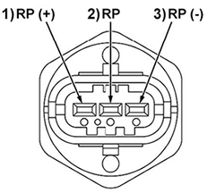
5.13.12Measuring Power Supply Voltage - Rail Pressure Sensor
This procedure is to diagnose whether the sensor is damaged. This procedure is related to DTC code P0192 and P0193.
1.Remove the connector of the rail pressure sensor.
2.Turn the ignition switch to “RUN” and measure the voltage between the connector terminals (2 and 3) on the rail pressure sensor wire harness side. Voltage should be approximately 5V.
•If voltage is normal, the rail pressure sensor is damaged. Replace the rail.
•If voltage is abnormal, measure the power supply voltage of the ECU connectors. See Section 5.13.47 for procedure.
5.13.13Measuring Power Supply Voltage of ECU Connectors - Rail Pressure Sensor
This procedure is to diagnose whether the problem is the wire harness power supply voltage line (including connectors) or the ECU. This procedure is related to DTC code P0192 and P0193.
1.Turn the ignition switch to “RUN” and measure the voltage between terminals 32 (Tester +) and 76 (Tester -) of the ECU. Voltage should be approximately 5V.
•If voltage is normal, repair or replace the wire harness (including connectors).
•If voltage is abnormal, check the ECU connectors. See Section 5.13.47 for procedure.
5.13.14Checking Injector Driving Circuit
This procedure is related to DTC codes P0193 and P0200.
1.Disconnect the injector connector.
2.Measure the voltage between the injector connector at the harness side. Voltage should be approximately 12V.
•If voltage is normal, check the injectors. See Section 5.13.15 for procedure.
•If voltage is abnormal, replace the ECU.
5.13.15Checking Injectors
This procedure is related to DTC codes P0193 and P0200
NOTE: Before diagnosing the problem, use Diagmaster to try to reproduce it based on any DTC information. Check the injector related signals on the Data Monitor screen.
1.Measure the resistance between injector terminals 1 (-) and 2 (+). Resistance should be approximately 0.22 to 0.30 Ω.
•If resistance is normal, then no action to take. If the DTC continues to appear, then replace the ECU.
•If resistance is abnormal, replace the injector.
5.13.16Checking Injectors (Open Circuit of Harness)
This procedure is related to DTC codes P0201, P0202, P0203 and P0204.
NOTE: Before diagnosing the problem, use Diagmaster to try to reproduce it based on any DTC information. Check the injector related signals on the Data Monitor screen.
1.Disconnect the injector connector
2.Measure the resistance between injector terminals of the cylinder indicating a DTC. Resistance should be approximately 0.22 to 0.30 Ω.
•If resistance is normal, then check the wire harness. See Section 5.13.17 for procedure.
•If resistance is abnormal, replace the injector.
5.13.17Checking a Wire Harness for Disconnection - Injectors
This procedure is related to DTC codes P0201, P0202, P0203 and P0204.
1.Disconnect the injector and the ECU from the connector.
2.Measure the resistance between the injector connector at the harness side and the ECU connector at the harness side. Terminals to measure:
•Injector #1: injector terminal 1 (-) and ECU terminal 3; injector terminal 2 (+) and ECU terminal 73
•Injector #2: injector terminal 1 (-) and ECU terminal 5; injector terminal 2 (+) and ECU terminal 51
•Injector #3: injector terminal 1 (-) and ECU terminal 5; injector terminal 2 (+) and ECU terminal 29
•Injector #4: injector terminal 1 (-) and ECU terminal 3; injector terminal 2 (+) and ECU terminal 7
3.Check that resistance is about 0.4 Ω.
•If resistance is normal, repair or replace the wire harness (connectors).
•If resistance is abnormal, check the ECU connectors. See Section 5.13.47 for procedure.
5.13.18Check DTCs and Verify Injector Correction
This procedure is related to DTC code P0602.
Refer to the Diagmaster section for detailed operating procedures for using Diagmaster.
1.Turn the ignition switch to RUN position.
2.Connect a computer to the ECU and open Diagmaster software.
3.Bring up the DTC screen and clear the DTC(s).
4.Bring up the Utility screen and perform an injector compensation on all injectors.
5.Turn the ignition switch OFF and then back to RUN.
6.Turn the ignition switch to START to start the engine.
7.Check whether or not the same DTC is detected. An electromagnetic interference (EMI) may have caused the temporary malfunction.
•If the DTC is not detected, then the system has recovered.
•If the DTC is detected again, then replace the ECU.
5.13.19Checking for a Ground Short - Injectors
This procedure is related to DTC codes P062D, P0643 and P2148.
1.Disconnect the injector connectors.
2.Check for ground short circuits inside the injectors by testing the continuity between body ground and the terminals of each injector (1, 2).
•If continuity is normal, check the wire harness for a ground short circuit. See Section 5.13.20.
•If continuity is abnormal, replace the injector.
5.13.20Checking a Wire Harness for Ground Short Circuit - Injectors
This procedure is related to DTC codes P062D, P0643 and P2148.
1.Disconnect the injectors and ECU from their connectors.
2.Check for ground short circuits in the wire harness by testing the continuity between body ground and the terminals. Terminals to measure:
•Injector #1: ECU terminals 3 and 73
•Injector #2: ECU terminals 5 and 51
•Injector #3: ECU terminals 5 and 29
•Injector #4: ECU terminals 3 and 7
•If continuity is normal, check the wire harness for +B short. See Section 5.13.21.
•If continuity is abnormal, repair or replace the wire harness.
5.13.21Checking a Wire Harness for +B Short Circuit - Injectors
This procedure is to diagnose whether the wire harness power supply is short circuited. This procedure is related to DTC codes P062D, P0643 and P2148.
1.Disconnect the injectors and ECU from their connectors.
2.Check whether the wire harness power supply is short circuited and check each terminal and the power supply for continuity. Refer to table below:
|
Terminals to Measure |
Power Supply Points to Measure |
|
|
Injector connector harness side terminals |
Positive terminal, negative terminal |
Feed pump Each switch Each lamp |
|
ECU connector harness side terminals |
3, 5, 7, 29, 51, 73 |
|
3.Check that there are no short circuits.
•If normal, check the ECU connectors. See Section 5.13.47.
•If abnormal, repair or replace the wire harness.
5.13.22Diagnosing an Overheating Condition or Improper Rise in Temperature
This diagnostic procedure is to systematically check the components suspected of causing an overheating condition. This procedure is related to DTC code P0217.
1.Inspect items from the pre-work checklist, Section 6.2, to make sure the criteria regarding the coolant system are met. Make sure coolant quantity and quality are meeting the proper standards.
2.Check the condition of the fan belt. See Section 6.4.4.4 for procedure.
3.Turn the ignition switch to START to start the engine.
4.Check the coolant level in the radiator after a warm up.
•If the level does not rise, check the water pump, thermostat or fan drive.
•If the level rises, check the radiator cap, radiator or coolant concentration.
5.Connect a computer to the ECU and launch Diagmaster software. See Section 7.2.4.
6.Bring up the Data Monitor screen, select the following coolant temperature signals for monitoring and then record the measurement.
•Coolant Temperature
•Coolant Temperature Sensor Output Voltage
See Section 7.3.7 for instructions on setting up measurements from the Data Monitor screen.
7.Observe the data on screen when the engine is running.
•If temperature does not change or fails to rise more than a certain amount, then check the coolant temperature sensor.
•If temperature rises slowly, then check the thermostat.
8.Repair or replace any abnormal areas.
5.13.23Checking Power Supply Voltage - Crankshaft Position Sensor
This procedure is related to DTC codes P0335 and P0336.
NOTE: Before diagnosing the problem, use Diagmaster to try to reproduce it based on any DTC information. Check the related signals on the Data Monitor screen. Diagnose whether it is the ECU (including connectors) or something else.
1.Disconnect the connector of the crankshaft position sensor.
2.Turn the ignition switch to “RUN” and measure the voltage between connector terminals 1 and 3 on the crankshaft position sensor wire harness side. Voltage should be approximately 5V.
•If voltage is normal, check around the crankshaft position sensor. See Section 5.13.26 for procedure.
•If voltage is abnormal, check the wire harness for disconnection. See Section 5.13.24 for procedure.

5.13.24Checking a Wire Harness for Disconnection - Crankshaft Position Sensor
This procedure is related to DTC codes P0335 and P0336.
1.Disconnect the connector of the crankshaft position sensor and the connector of the ECU.
2.Measure the resistance between connector terminals on the crankshaft position sensor wire harness side and ECU connector at the harness side. Terminals to measure:
•Sensor terminal 1 and ECU terminal 39
•Sensor terminal 2 and ECU terminal 75
•Sensor terminal 3 and ECU terminal 8.
3.Check that resistance is several Ω and more.
•If resistance is normal, measure the power supply voltage of the ECU connectors. See Section 5.13.25 for procedure.
•If resistance is abnormal, repair or replace the wire harness (connectors).
5.13.25Checking Power Supply Voltage of ECU Connectors - Crankshaft Position Sensor
This procedure is related to DTC codes P0335 and P0336.
1.Turn the ignition switch to RUN and measure the voltage between terminals 39 (+) and 8 (-) of the ECU. Voltage should be approximately 5V.
•If voltage is normal, then there is no abnormality, this is a temporary error.
•If voltage is abnormal, check the ECU connectors. See Section 5.13.47 for procedure.
5.13.26Checking Around the Crankshaft Position Sensor
This procedure is related to DTC codes P0335 and P0336.
1.Inspect the flywheel for the following:
•Installation not misaligned
•No foreign matter adhering
2.Inspect the crankshaft position sensor to make sure no foreign matter is stuck to the sensor surface.
5.13.27Checking Power Supply Voltage - Camshaft Position Sensor
This procedure is related to DTC codes P0340 and P0341.
NOTE: Before diagnosing the problem, use Diagmaster to try to reproduce it based on any DTC information. Check the related signals on the Data Monitor screen. Diagnose whether it is the ECU (including connectors) or something else.
1.Disconnect the connector of the camshaft position sensor.
2.Turn the ignition switch to “RUN” and measure the voltage between connector terminals 1 and 2 on the camshaft position sensor wire harness side. Voltage should be approximately 5V.
•If voltage is normal, check around the camshaft position sensor. See Section 5.13.30.
•If voltage is abnormal, check the wire harness for disconnection. See Section 5.13.28.
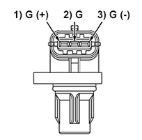
5.13.28Checking a Wire Harness for Disconnection - Camshaft Position Sensor
This procedure is related to DTC codes P0340 and P0341.
1.Disconnect the connector of the camshaft position sensor and the connector of the ECU.
2.Measure the resistance between connector terminals on the camshaft position sensor wire harness side and ECU connector at the harness side. Terminals to measure:
•Sensor terminal 1 and ECU terminal 45
•Sensor terminal 2 and ECU terminal 46
•Sensor terminal 3 and ECU terminal 44.
3.Check that resistance is several Ω and more.
•If resistance is normal, measure the power supply voltage of the ECU connectors. See Section 5.13.29 for procedure.
•If resistance is abnormal, repair or replace the wire harness (connectors).
5.13.29Checking Power Supply Voltage of ECU Connectors - Camshaft Position Sensor
This procedure is related to DTC codes P0340 and P0341.
1.Turn the ignition switch to “RUN” and measure the voltage between terminals 45 (+) and 44 (-) of the ECU. Voltage should be approximately 5V.
•If voltage is normal, then there is no abnormality, this is a temporary error.
•If voltage is abnormal, check the ECU connectors. See Section 5.13.47 for procedure.
5.13.30Checking Around the Camshaft Position Sensor
This procedure is related to DTC codes P0340 and P0341.
1.Inspect the camshaft position pulsar gear for the following:
•Installation not mis-aligned
•No foreign matter adhering
•Teeth not worn
2.Inspect the camshaft position sensor for the following:
•No foreign mater stuck to sensor surface
•No trace of interference with cam position pulsar gear
5.13.31Checking a Wire Harness - Glow Relay
This procedure is related to DTC codes P0380 and P0381.
NOTE: Before diagnosing the problem, use Diagmaster to try to reproduce it based on any DTC information. Check the related signals on the Data Monitor screen. Diagnose whether the wire harness (including connectors) is damaged or something else is.
NOTE: The glow relay turns OFF at coolant temperatures above 21°C (70°F).
1.Disconnect the connector from the ECU.
2.Disconnect the glow relay from the connector.
3.Check the conduction of the wire harness at glow relay terminal 4 and ECU terminal 70. Check for continuity.
•If continuity is normal, check the glow relay.
•If continuity is abnormal, repair or replace the wire harness (connectors).
5.13.32Checking the Operation of a Relay - Glow Relay
This procedure is for checking the relay separately and deciding whether the relay is the problem. This involves 3 tests: measuring voltage, checking continuity, and measuring resistance. Relay specifications vary with the engine. This procedure is related to DTC codes P0380 and P0381.
1.Measure voltage. Remove the connector of the coolant temperature sensor and connect a dummy resistor.
NOTE: The dummy resistor: 15 to 25 kΩ [comparable to approximately -30 to -20°C (-22 to -5°F). The glow relay comes on when the coolant temperature is below 10°C (50°F).
2.Turn the ignition switch to RUN and measure the voltage of the glow relay between relay terminals 3 and 4.
3.The voltage should be equivalent to the generator set battery voltage value.
•If voltage is normal, check the ECU connectors. See Section 5.13.47.
•If voltage is abnormal, replace the glow relay.
4.Check continuity. Remove the connector of the coolant temperature sensor and connect a dummy resistor.
NOTE: The dummy resistor: 15 to 25 kΩ [comparable to approximately -30 to -20°C (-22 to -5°F). The glow relay comes on when the coolant temperature is below 21°C (70°F).
5.Turn the ignition switch to “RUN” and check continuity between the glow plug relay terminals 1 and 2. There must be continuity.
•If continuity is normal, check the ECU connectors. See Section 5.13.47.
•If continuity is abnormal, replace the glow plug relay.
6.Measure resistance. Disconnect the glow relay from the connector.
7.Measure the resistance between the glow relay terminals 3 and 4.
8.Verify the resistance is within specification.
•If resistance is normal, check the ECU connectors. See Section 5.13.47.
•If resistance is abnormal, replace the glow plug relay.
5.13.33Checking the Operation of the Low Oil Pressure Switch
This procedure is related to DTC code P0524.
When checking the low oil pressure (LOP) switch, if the engine oil level is low then the engine may be damaged. So, limit the time the amount of time that the engine is started.
1.Connect a computer to the ECU and open Diagmaster. See Section 7.2.4 for procedure.
2.Launch Diagmaster software. See Section 7.3.1 for procedure.
3.Turn the ignition switch to START to start or RUN for diagnosis purposes.
4.Go to the Data Monitor screen and bring up the Oil Pressure SW setting.
5.Observe the data on the screen to diagnose the ON/OFF state of the low oil pressure (LOP) switch signal.
•When the ignition switch is in START (engine running), the LOP switch status should be ON.
•When the ignition switch is in RUN (engine stopped), the LOP status should be OFF.
6.For further diagnosis, disconnect the LOP connector.
7.Set up the conditions and check for continuity between the LOP switch terminal and body ground. Continuity should be present with ignition switch in RUN (engine stopped). Continuity should not be present when the engine is running.
•If continuity is normal, check the wire harness. See Section 5.13.34.
•If continuity is abnormal, replace the LOP switch. See Section 6.4.3.2.
5.13.34Checking a Wire Harness - Low Oil Pressure Switch
This procedure is to diagnose whether the problem is the wire harness (including connectors) or something else. This procedure is related to DTC code P0524.
1.Disconnect the sensors and the ECU from the connector.
2.Check the continuity of the harness at the oil pressure switch terminal and ECU terminal 47.
•If continuity is normal, check the engine oil pressure.
•If continuity is abnormal, repair or replace the wire harness (connectors).
3.Check for short circuits between the terminals of the oil pressure switch and those of the ECU by testing continuity between body ground and each terminal.
•If there are no short circuits, check the engine oil pressure. See Section 6.4.4.2.
•If short circuits are found, repair or replace the wire harness (connectors).
5.13.35Checking Resistance - Suction Control Valve (SCV)
This procedure is to diagnose whether the problem is the ECU (including the connectors) or something else. This procedure is related to DTC codes P0627, 0628 and 0629.
1.Disconnect the ECU connector from the ECU.
2.Measure the resistance on the ECU connector side at terminals 4 and 89. Resistance specification is: Temperature: 20°C (68°F); Resistance: 2.6 to 3.5 Ω; Insulation resistance (between terminal and body): 100 MΩ or higher.
•If resistance is normal, check the ECU connectors. See Section 5.13.47.
•If resistance is abnormal, check the SCV sensor wire harness. See Section 5.13.36.
5.13.36Checking a Wire Harness - Suction Control Valve (SCV)
This procedure is to diagnose whether the problem is the SCV sensor wire harness (including connectors). This procedure is related to DTC codes P0627, 0628 and 0629.
1.Disconnect the SCV connector.
2.Measure the resistance between the terminals on the SCV sensor. Resistance specification is: Temperature: 20°C (68°F); Resistance: 2.6 to 3.5 Ω; Insulation resistance (between terminal and body): 100 MΩ or higher.
•If resistance is normal, repair or replace the wire harness (including connectors).
•If resistance is abnormal, replace the SCV or supply pump unit.
5.13.37Checking ECU Terminal Voltage
This procedure is related to DTC codes P0562 and P0563.
1.Set up the conditions and measure the voltage between ECU terminals. Terminals to measure:
•Terminal 4 battery (+) and terminals 1,2 power ground (-).
•Terminal 6 battery (-) and terminals 1,2 power ground (-).
2.Voltage with engine operating should be 8 to 16V.
•If voltage is normal, check the ECU connectors. See Section.
•If voltage is abnormal, continue with the next step of this procedure.
3.Set up the conditions and measure the voltage between body earth and ECU terminals 1,2 power ground.
4.Voltage with engine operating should be 0.5 V or lower.
•If voltage is normal, check the charging system, the battery itself, the wire harness and cables.
•If voltage is abnormal, check the wire harness between the ECU terminals and body ground terminals.
5.13.38Checking the Operation of a Relay - Main Relay / Engine Relay
This procedure is a general relay checking procedure. This procedure is related to DTC code P0687.
1.Disconnect the relay.
2.Turn the ignition switch to RUN and measure the voltage between terminals 1 and 3 on the relay connector side. Voltage should be equivalent to the battery voltage value.
•If voltage is normal, check the relay.
•If voltage is abnormal, check for open circuits in the harness between terminals of the relay and the battery and repair or replace as needed.
3.Check for continuity between terminals 3 and 4 of the relay.
•If continuity is normal, check for continuity between terminals 1 and 2 of the relay. There is resistance in the relay coil, so it should be 0 Ω. Check for an open circuit
•If continuity is abnormal, replace the relay.
4.Check for continuity between terminals 1 and 2 of the individual relay when the relay is ON. Apply a battery voltage to relay terminals 3 and 4 to turn it ON. Check for continuity between terminals 1 and 2 and check whether the contacts of the relay are normal or not.
•If continuity is normal, check the input/output voltage of the ECU-side relays.
•If continuity is abnormal, replace the relay.
5.13.39Checking Input / Output Voltage of ECU Side Relays
This procedure is related to DTC code P0687.
1.Turn the ignition switch to RUN and check the voltage of the input terminal 4 and 6 on the ECU side of the main relay. Voltage should be equivalent to the battery voltage value.
•If voltage is normal, replace the ECU.
•If voltage is abnormal, check the wire harness and connectors between the relays and ECU. If there are no open or short circuits, check the voltage of the output terminals 50 of the ECU side of the main relay.
2.Turn ignition switch to OFF and then RUN. Measure the voltage of the output terminals 50 on the ECU side of the main relay. There should be no change in voltage.
•If voltage is normal, check for open circuits in the harness between the relay and the ECU. Repair and replace.
•If voltage is abnormal, replace the ECU.
5.13.40Checking a Wire Harness - Starter Relay
This procedure is related to DTC code P081A.
NOTE: Before diagnosing the problem, use Diagmaster to try to reproduce it based on any DTC information. Check the related signals on the Data Monitor screen. Diagnose whether the wire harness (including connectors) is damaged or something else is.
1.Disconnect the connector from the ECU.
2.Disconnect the starter relay from the connector.
3.Check the conduction of the wire harness at starter relay terminal 3 and ECU terminal 68. Check that there is continuity.
•If continuity is normal, check the starter relay. See Section 5.13.41.
•If continuity is abnormal, repair or replace the wire harness (connectors).
5.13.41Checking the Operation of a Relay - Starter Relay
This procedure is for checking the relay separately and deciding whether the relay is the problem. This involves 3 tests: measuring voltage, checking continuity, and measuring resistance. Relay specifications vary with the engine; this procedure is a general failure diagnosis of a starter relay. This procedure is related to DTC code P081A.
1.Measure voltage. Turn the ignition switch to RUN and measure the voltage of the glow relay between relay terminals 3 and 4. The voltage should be equivalent to the generator set battery voltage value.
•If voltage is normal, check the ECU connectors. See Section 5.13.47.
•If voltage is abnormal, replace the starter relay.
2.Check continuity. Remove the connector of the coolant temperature sensor and connect a dummy resistor.
NOTE: The dummy resistor: 15 to 25 kΩ [comparable to approximately -30 to -20°C (-22 to -5°F). The glow relay comes on when the coolant temperature is below 21°C (70°F).
3.Turn the ignition switch to RUN and check continuity between the starter relay terminals 1 and 2. There must be continuity.
•If continuity is normal, check the ECU connectors. See Section 5.13.47 for procedure.
•If continuity is abnormal, replace the starter relay.
4.Measure resistance. Disconnect the starter relay from the connector.
5.Measure the resistance between the starter relay terminals 3 and 4. Verify the resistance is within specification.
•If resistance is normal, check the ECU connectors. See Section 5.13.47 for procedure.
•If resistance is abnormal, replace the starter relay.
5.13.42Checking DTCs and Rewriting Trim Data
If trim data is written, such as when the ECU is replaced, it may fail. If so, retry doing it. This procedure is related to DTC code P1990.
Refer to the Diagmaster chapter for detailed operating procedures for using Diagmaster.
1.Turn the ignition switch to RUN position.
2.Connect a computer to the ECU and open Diagmaster software.
3.Bring up the DTC screen and clear the DTC(s).
4.Check whether or not the same DTC is detected. An electromagnetic interference (EMI) may have caused the temporary malfunction.
•If the DTC is not detected, then the system has recovered.
•If the DTC is detected again, then continue to next step of this procedure.
5..Write trim data correctly to the ECU.
6.Clear the DTC
7.Turn the ignition switch OFF and then back to RUN.
8.Check whether or not the same DTC is detected. If same DTC is detected and can not be cleared, replace the ECU.
5.13.43Checking DTCs and the Atmospheric Pressure Sensor
The atmospheric pressure sensor is built into the ECU, so a simple check can not be performed. Check the DTC to determine whether it is damaged. This procedure is related to DTC codes P2228 and P2229.
Refer to the Diagmaster chapter for detailed operating procedures for using Diagmaster.
1.Turn the ignition switch to RUN position.
2.Connect a computer to the ECU and open Diagmaster software.
3.Bring up the DTC screen and clear the DTC(s).
4.Check whether or not the same DTC is detected. An electromagnetic interference (EMI) may have caused the temporary malfunction.
•If the DTC is not detected, then the system has recovered.
•If the DTC is detected again, then the atmospheric pressure sensor is damaged. Replace the ECU.
5.13.44Checking DTCs after a Pressure Limiter Failure
This procedure is related to DTC code P2293.
Refer to the Diagmaster chapter for detailed operating procedures for using Diagmaster.
1.Turn the ignition switch to RUN position.
2.Connect a computer to the ECU and open Diagmaster software.
3.Bring up the DTC screen and clear the DTC(s).
4.Turn the ignition OFF and then back to RUN.
5.Turn the ignition to START to start the engine.
6.Check whether or not the same DTC is detected. An electromagnetic interference (EMI) may have caused the temporary malfunction.
•If the DTC is not detected, then the system has recovered.
•If the DTC is detected again, then replace the ECU
5.13.45Checking DTCs and CAN2 Related Wiring
This procedure is related to DTC code U0075.
Refer to the Diagmaster chapter for detailed operating procedures for using Diagmaster.
1.Turn the ignition switch to RUN position.
2.Connect a computer to the ECU and open Diagmaster software.
3.Bring up the DTC screen and clear the DTC(s).
4.Check whether or not the same DTC is detected. An electromagnetic interference (EMI) may have caused the temporary malfunction.
•If the DTC is not detected, then the system has recovered.
•If the DTC is detected again, then continue to the next step of this procedure.
5.Disconnect the CAN2 connector and the ECU from the connector.
NOTE: The position and shape of the CAN2 connector varies with specifications.
6.Check the continuity of the harness between the CAN2 connector terminal and ECU terminal 62, 63. All harnesses must have continuity.
•If continuity is normal, replace the ECU.
•If continuity is abnormal., repair or replace any abnormal areas.
7.Check for short circuits between the terminals of CAN2 connector and those of the ECU by testing the continuity between body ground and each terminal 62, 63.
•If no shorts are present, replace the ECU.
•If shorts are present, repair or replace any abnormal areas.
5.13.46Checking DTCs and CAN1 Related Wiring
This procedure is related to DTC code U0077.
Refer to the Diagmaster section for detailed operating procedures for using Diagmaster.
1.Turn the ignition switch to RUN position.
2.Connect a computer to the ECU and open Diagmaster software.
3.Bring up the DTC screen and clear the DTC(s).
4.Check whether or not the same DTC is detected. An electromagnetic interference (EMI) may have caused the temporary malfunction.
•If the DTC is not detected, then the system has recovered.
•If the DTC is detected again, then continue to the next step of this procedure.
5.Disconnect the CAN1 connector and the ECU from the connector.
NOTE: The position and shape of the CAN1 connector varies with specifications.
6.Check the continuity of the harness between the CAN1 connector terminal and ECU terminal 65, 66. All harnesses must have continuity.
•If continuity is normal, replace the ECU.
•If continuity is abnormal., repair or replace any abnormal areas.
7.Check for short circuits between the terminals of CAN1 connector and those of the ECU by testing the continuity between body ground and each terminal 65, 66.
•If no shorts are present, replace the ECU.
•If shorts are present, repair or replace any abnormal areas.
5.13.47Checking the ECU Connectors
This procedure is to diagnose whether the ECU or connectors on the ECU harness side has a malfunction.
1.Inspect the state of the ECU connector pins for the following items:
•No breakage or bending
•No foreign matter adhering
2.Inspect the state of the ECU connector at the harness side for the following items:
•ECU connector pins must fit together securely
•No foreign matter adhering
3.If no abnormalities are noticed, then replace the ECU.