Service and Preventative Maintenance
NOTE: Read the Safety chapter carefully prior to troubleshooting the engine or generator set.
The Kubota Engine Park (KEP) website provides access to additional resources for operating, servicing and troubleshooting Kubota engines. From here, a user can download Diagmaster diagnosis software, application manuals, and service manuals. Contact a Carrier service engineer to request login credentials.
KEP can be accessed by visiting https://ba.engine.kubota.com/web/guest/home
6.2Engine Pre-Work Checklist
Prior to performing any failure diagnosis work, check and record the content of the engine pre-work checklist in order to check the engine’s state of use.
Table 6–1 Engine Pre-Work Checklist
|
Oil |
Quantity |
High |
Suitable |
Low |
|
|
Contamination |
None |
Has |
|||
|
Smell |
None |
Has |
|||
|
Leakage |
None |
Has |
|||
|
Grade |
Suitable |
Not suitable |
|||
|
Storage state |
Suitable |
Not suitable |
|||
|
Fuel |
Quantity |
Full |
Middle |
Low |
|
|
Contamination |
None |
Has |
|||
|
Smell |
None |
Has |
|||
|
Leakage |
None |
Has |
|||
|
Quality |
Suitable |
Not suitable |
|||
|
Storage state |
Suitable |
Not suitable |
|||
|
Coolant |
Radiator |
Quantity |
High |
Suitable |
Low |
|
Contamination |
None |
Has |
|||
|
Smell |
None |
Has |
|||
|
Leakage |
None |
Has |
|||
|
Reserve tank |
Quantity |
High |
Suitable |
Low |
|
|
Contamination |
None |
Has |
|||
|
Smell |
None |
Has |
|||
|
Leakage |
None |
Has |
|||
|
Wiring (connector) |
Contamination |
None |
Has |
||
|
Broken |
None |
Has |
|||
|
Damaged |
None |
Has |
|||
|
Air cleaner |
Contamination |
None |
Has |
||
|
Clogging |
None |
Has |
|||
|
Broken |
None |
Has |
|||
|
Water separator |
Water mixed in |
None |
Has |
||
|
Contamination |
None |
Has |
|||
|
Fuel filter |
Genuine parts |
Yes |
No |
||
|
Oil filter |
Genuine parts |
Yes |
No |
||
|
Modification |
Fuel system |
None |
Has |
||
|
Electrical system |
None |
Has |
|||
6.3Generator Set and Engine Maintenance Schedule
A tabular listing of the recommended preventative maintenance activities and schedule is provided in Table 6–2.
Table 6–2 Preventative Maintenance Actions and Schedule
|
Reference |
Daily or Pre-Trip1 |
1 Yr2 |
2 Yr3 |
4 Yr4 |
|
|---|---|---|---|---|---|
|
Engine |
|||||
|
Check (in place) engine shockmounts visually for cracks, cuts, abrasions. |
x |
x |
|||
|
Replace engine shockmounts |
x |
x |
|||
|
Tighten engine mounting bolts. |
x |
x |
x |
||
|
Check valve clearance. |
Engine Manual |
x |
x |
||
|
Check crankcase breather. |
none |
x |
x |
||
|
Check for historical DTC codes. |
x |
x |
|||
|
Engine - Fuel System |
|||||
|
Check fuel lines, filters, clamp bands and connections for leaks. |
none |
x |
x |
x |
x |
|
Check tank fuel level, refuel as needed. Check fuel gauge operation. |
x |
x |
x |
x |
|
|
Replace the fuel filter element. |
x |
x |
x |
||
|
Drain water from the fuel filter bowl. If the bowl has water, drain water from the fuel tank sump. |
none |
x |
x |
x |
x |
|
Engine - Lubrication System |
|||||
|
Check lubrication filters and seals for leaks. |
none |
x |
x |
x |
|
|
Check lubrication oil level, add as required. |
x |
||||
|
Change lubrication oil and oil filter (See NOTES). |
x |
x |
x |
||
|
Engine - Coolant System |
|||||
|
Check coolant system lines, clamp bands and connections for leaks. |
none |
x |
x |
x |
x |
|
Check radiator coil for cleanliness. |
x |
x |
x |
x |
|
|
Check coolant level. Add 50/50 mix as required. |
x |
x |
x |
||
|
Clean and flush the coolant system. |
x |
||||
|
Check fan belt for fraying or cracking. Replace as required. |
x |
x |
x |
x |
|
|
Check water pump bearing end play. |
none |
x |
x |
||
|
Engine - Intake and Exhaust System |
|||||
|
Check the air cleaner element, air filter minder (indicator) and air intake line. Clean / replace filter as needed. |
x |
x |
x |
x |
|
|
Check exhaust system for leaks. |
none |
x |
x |
x |
x |
|
Electrical System |
|||||
|
Check battery terminals for tightness and cleanliness. |
none |
x |
x |
x |
x |
|
Clean and coat battery terminals with sealant. |
none |
x |
x |
x |
|
|
Check for dirty or loose electrical connections, frayed cables, cracked insulation. |
none |
x |
x |
x |
x |
|
Tighten all electrical connections in the control box. |
none |
x |
x |
x |
|
|
Check the starter condition. |
none |
x |
x |
x |
|
|
Generator |
|||||
|
Check (in place) generator shockmounts visually for cracks, cuts, abrasions. |
x |
x |
|||
|
Replace generator shockmounts |
x |
x |
|||
|
Tighten generator mounting bolts. |
x |
x |
x |
||
|
Check generator output with a voltmeter. |
x |
x |
x |
x |
|
|
General |
|||||
|
Inspect unit for debris within the drive assembly interior and discard. |
none |
x |
x |
x |
x |
|
Check and tighten as required all hardware, brackets, etc. |
none |
x |
x |
x |
x |
|
Check total time meter operation (allow engine to run 10 minutes). |
none |
x |
x |
x |
x |
|
Listen for abnormal noises. |
none |
x |
x |
x |
x |
|
Turn container unit on and check generator 1800 rpm under full load. |
none |
x |
x |
x |
x |
|
Verify operation of safety devices. |
x |
x |
x |
||
NOTES ON LUBRICATING OIL AND FILTERS:
•Units have mineral oil installed from the factory. Change lubricating oil and filters after the first 2000 hours of service or at the end of the first year, whichever comes first.
•Oil changes after the first 2000 hour service, or 1 year:
•If using mineral oil, oil changes should continue every 2000 hours of service or every 1 year, whichever comes first.
•If using specified synthetic lubricating oil and OEM extended life oil filter, oil changes should be completed every 4000 hours of service, or every two years, whichever comes first.
1 Pre-trip maintenance checks should be carried out prior to any use of the unit (1-15 and 31-36).
2 One year maintenance checks should be carried out annually or every 2000 hours, whichever comes first.
3 Two year maintenance checks should be carried out every two years or every 4000 hours, whichever comes first.
4 Four year maintenance checks should be carried out every four years or every 8000 hours, whichever comes first.
Engine service procedures are included in this section. Any procedures not included can be referenced from one of the Kubota reference manuals.
A separate manual, 62-12258 Diesel Engine Workshop for V2403-CR-E4B Engines, is available to cover information not detailed in this operations and service manual.
6.4.1Fuel System Service
The engine fuel system, as described in Section 3.7, is a common rail system (CRS) that injects a precise amount of atomized fuel into the engine cylinders.
NOTE: The generator set approved fuel is Ultra Low Sulfur Diesel (ULSD) or diesel with < B5 (5% biodiesel).
NOTE: Prior to performing any diagnosis work on the fuel system, refer to the pre-work checklist located in Section 6.2, to make sure all criteria are met.
NOTE: Be sure to read and understand all safety precautions, located in Section 1.4, related to fluids and the fuel system prior to performing work.
NOTE: Make sure fuel quality meets the fuel standard, fuel quantity is at the specified amount and there are no leaks. Fuel specifications are described in Section 3.15.
NOTE: Be sure to use a strainer when filling the fuel to prevent dirt or debris from entering the tank.
NOTE: Do not operate the fuel tank level too low or completely out of fuel. This may cause improper engine operation and/or a DTC error code may be recorded in the ECU.
1.Check inside the fuel tank. Inspect for contaminants, water separation, and rust.
2.If the fuel tank has been modified or expanded, check the following items:
•Tank material: resin
•Inside tank: contaminants, water separation, rust
•Fuel inlet/outlet: position and piping
•Fuel pipe inside tank: inlet/outlet position (below empty position)
•Fuel pipe inside tank: inlet clogged, pipe bent or deformed (crushed)
•Fuel pipe inside tank: pipe connection crushed
3.If a problem is not found, clean or replace the fuel tank.
6.4.1.2Checking the Fuel Lines and Pipes
1.Check the fuel line hoses for the following: deterioration, disconnection, perforation, cracking, or being pinched, crushed or excessively bent by other parts.
2.Check the fuel line clamps for looseness, crushing, or excessive bending.
3.Check for any traces of leaked fuel.
4.For high pressure pipes, check visually for leaks outside the engine. And also inside the head cover check for an increase in engine oil amount.
5.Repair or replace any problem areas or components.
6.4.1.3Bleeding the Fuel System
The fuel system is a closed circuit which will require bleeding if changing a fuel filter, opening fuel lines for any reason or if the system has been emptied of fuel.
1.Make sure the fuel tank has adequate fuel.
2.Check the tightness of all fuel and filter connections.
3.Operate the hand primer pump until pressure increases.
4.Start the engine.
6.4.1.4Replacing the Fuel Filter
Do not pre-fill a new replaced fuel filter prior to installation. This can damage the engine’s fuel injectors.
1.To replace the fuel filter, loosen and remove the filter housing.
2.Lightly oil new gasket with lube oil
3.Replace the filter.
NOTE: If the generator set is equipped with the fuel filter bowl assembly, when replacing the fuel filter, a new fuel filter O-ring should be oiled and replaced. The clear bowl is then tightened to 18 ft-lbs (24.4 Nm).
6.4.2Engine Air Cleaner Service
The engine air cleaner, as described in Section 3.8.1, uses a dry element filter to clean the engine intake air.
The engine air cleaner should be inspected regularly for leaks or clogging. A damaged air cleaner or hose can seriously affect the performance and life of the engine. The air cleaner is designed to effectively remove contaminants from the air stream entering the engine. An excessive accumulation of contaminants in the air cleaner will impair its operation. Therefore, a service schedule must be set up and followed.
The air cleaner element should be replaced after six cleanings.
Always cover the engine inlet tube while the air cleaner is being serviced.
1.Check all connections for mechanical tightness. Be sure the air cleaner outlet pipe is not fractured.
2.In case of leakage, if adjustment does not correct the problem, replace necessary parts or gaskets. Swollen or distorted gaskets must always be replaced.
The air filter indicator, see Figure 3.19, is mounted on the air filter body. Its function is to indicate when the air cleaner dry element needs to be replaced. In operation, when a plugged air cleaner decreases intake manifold pressure to 500mm (20”) WG, the indicator moves to the red line. The air cleaner element should be replaced and the indicator reset by pressing the reset button.
6.4.2.2Air Cleaner Dry Element Service
1.Stop the engine and open the cap clamps to remove the air cleaner bottom cap.
2.Remove the air filter element from the air cleaner body.
3.Install the new element, and secure the bottom cap with the cap clamps.
6.4.2.3Air Cleaner Body Service
If there is any sign of contaminant buildup or plugging, the air cleaner body should be removed and back flushed. At least once a year, or at regular engine service intervals, remove the entire air cleaner and perform the following cleaning procedure:
Do not use gasoline to clean air cleaner parts.
1.Check and clean the center tube.
2.Pump solvent through the air outlet with sufficient force and volume to produce a hard, even stream out of the bottom of the body assembly. Reverse flush until all foreign material is removed.
6.4.2.4Air Cleaner Intake Air Line
Check whether there is an air leak in the intake air path. Observe the following inspection locations:
•Looseness, misalignment or air cleaner sensor installation.
•Loose or missing suction pipe, hose or clamp.
•Hole or crack in suction pipe or hose.
•Deformed routing of the air intake lines.
6.4.3Lubrication System Service
The engine lubrication system, as described in Section 3.9, supplies lubricating oil to the various moving parts in the engine.
6.4.3.1Replacing the Lube Oil Filter
1.After warming up the engine, stop the engine, remove the drain plug from the oil reservoir and drain the oil.
2.Replace the filters. Lightly oil the gasket on the filter before installing.
3.Add lube oil as detailed in Table 3–4.
4.Warm up the engine and check for leaks.
6.4.3.2Servicing the Low Oil Pressure Switch
Make sure the engine is cooled down enough before removing the oil pressure switch. Be careful when removing the oil pressure switch as engine oil will flow out.
1.Remove harness connection from the low oil pressure (LOP) switch.
2.Remove the low oil pressure (LOP) switch from the engine.
3.Apply Teflon thread sealer to all threads of new the new switch.
4.Install the new switch.
5.Reconnect the harness connection to the new switch.
The engine cooling system, as described in Section 3.10, uses extended life coolant and a radiator to keep the engine from overheating.
6.4.4.1Cleaning the Cooling System
To ensure adequate cooling, the radiator must be clean, externally and internally. To service the cooling system, do the following:
1.Remove all foreign material from the radiator coil by reversing the normal air flow. Compressed air or water may be used as a cleaning agent. It may be necessary to use warm water mixed with any good commercial dishwasher detergent. Rinse coil(s) with fresh water if a detergent is used.
2.Drain coolant completely by opening the drain-cock and removing the radiator cap.
Never pour cold water into a hot engine.
3.Close the drain cock and fill the system with clean, untreated water to which between 3% and 5% of an alkaline base radiator cleaner should be added; 170 grams dry = 151 grams to 3.8 liters of water.
4.Run the engine 6 to 12 hours and drain the system while warm. Rinse the system three times after it has cooled down. Refill the system with water.
Use only ethylene glycol anti-freeze (with inhibitors) in system. Use of glycol by itself will damage the cooling system.
5.Run the engine to operating temperature. Drain the system again and fill with treated water / anti-freeze. See the above Caution statement.
6.4.4.2Checking Engine Oil Pressure
Make sure the engine is cooled down enough before removing the oil pressure switch. Be careful when removing the oil pressure switch as engine oil will flow out.
1.Check the amount of engine oil.
2.Remove harness connection from the low oil pressure (LOP) switch.
3.Remove the low oil pressure (LOP) switch from the engine.
4.Install an oil pressure tester.
5.Start the engine and let it warm up.
6.Set up the conditions and measure the engine oil pressure. Oil pressure specifications are detailed in Table 3–4. If pressure is not within specifications, inspect the oil, oil filter, relief valve, oil pump and oil clearances.
Beware of moving fan belt, belt driven components and hot exhaust components.
Beware of pinch points.
NOTE: A frayed, cracked or worn fan belt must be replaced. After installing a new belt, check the adjustment after running the unit for three or four hours. This will allow for the initial stretch, which is common on new belts. Once this initial stretch has taken place, the belt should be checked at regular intervals.
The fan belt is a poly V-belt that is driven by a sheave on the engine crankshaft. Its two functions are: (1) to drive the radiator fan and (2) to drive the water pump.
6.4.4.4Checking the Fan Belt
1.Check the belt for wear by looking for fraying or cracking. Observe whether the belt is sunken into the pulley groove.
2.Check fan belt tension. Push the belt half way between the fan drive pulley and alternator pulley at specified force to measure deflection.
1.Using the proper size socket, slowly rotate the crank on the crank pulley nut. At the same time, use a flat, blunt object to guide the belt off the crank pulley towards the radiator. Be careful not to damage grooves on the pulley.
2.Replace the belt by positioning the belt on the water pump pulley, and while rotating the engine (as in step 1.), use a flat, blunt object to guide the belt onto the crank pulley. Be careful not to damage grooves on the pulley or belt.
Observe proper polarity when installing the battery or connecting a battery charger. The negative battery terminal must be grounded. Reverse polarity may damage the charging system. When charging the battery in unit, isolate the battery by disconnecting the negative battery terminal first, then the positive. Once the battery has been charged, connect the positive battery terminal first, then the negative.
6.5.1Removing and Replacing the DOC
Before servicing the unit, make sure the unit is OFF and the negative battery terminal is disconnected. Follow your regional lockout tagout procedure.
Beware of moving poly V-belt, belt driven components and hot exhaust components.
Beware of pinch points.
1.Remove the genset cover and disconnect the battery. Follow local lockout / tagout procedures.
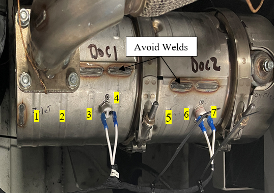
2.Electrically disconnect and remove the 2 thermal switches from the DOC that needs to be replaced. Set aside the switches to save for re-installation.
3.Remove the DOC from the genset and set the new DOC in place and secure.
4.Using the switches, mark and punch locations for drilling in the replacement DOC. Position so the switches are against the body of the DOC. Align between ribs 3 and 4 and between ribs 6 and 7, counting from the inlet side of the DOC. Make sure to avoid areas with welds.
Ensure the bracket goes along radius of the DOC. The switch brackets are positioned forward to sit above the battery charger at the 2 o'clock position when viewed from the outlet of the DOC.
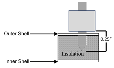
5.Drill holes through the outer shell of the DOC with a 0.129 to 0.133” drill bit and drill stop at 0.25” at the punched holes.
For non-potted switches, drill holes (2 per switch) through the outer shell of the DOC with a 0.129 to 0.133” drill bit and drill stop at 0.25” at the punched holes.
For potted switches, drill holes (2 per switch) through the outer shell of the DOC with a 0.160 to 0.164” drill bit and drill stop at 0.25” at the punched holes.
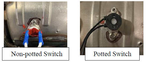
6.For non-potted switches, apply silicone (Permatex Ultra Red 81630 / 81624) to the rim of the switch to help seal it. Ensure the contact area remains clean.
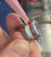
7.Position the switch over the holes with the rim flat to the body of the DOC.
8.Attach the switches to the DOC using 4 stainless steel rivets and a powered rivet tool to ensure tightness of installation. Ensure the bracket is flat against the switch head.
NOTE: Use a pneumatic or electronic rivet tool to ensure tightness of installation.
For non-potted switches, use small rivets (part # 34-00928-01).
For potted switches, use larger rivets (part # 34-00928-07).
9.Re-apply Permatex as needed to cover switch terminals for non-potted switches.
6.5.2Removing and Replacing the DOC Thermal Switches
Before servicing the unit, make sure the unit is OFF and the negative battery terminal is disconnected. Follow your regional lockout tagout procedure.
Beware of moving poly V-belt, belt driven components and hot exhaust components.
Beware of pinch points.
1.Remove the genset cover and disconnect the battery. Follow local lockout tagout procedures.
2.Electrically disconnect and remove the 2 thermal switches from the DOC.
3.All replacement switches are potted switches.
If the removed switch was potted, then the existing holes in the DOC can be used.
If the removed switch was non-potted, continue to the next step for hole drilling instructions.
4.Drill holes (2 per switch) through the outer shell of the DOC with a 0.160 to 0.164” drill bit and drill stop at 0.25” at the punched holes.
5.Attach the switches to the DOC using 4 stainless steel rivets (part # 34-00928-07) and a powered rivet tool to ensure tightness of installation. Ensure the bracket is flat against the switch head.
NOTE: Use a pneumatic or electronic rivet tool to ensure tightness of installation
When replacing the battery, note if the unit was supplied with a mat in the battery tray. If so equipped, the mat must also be replaced. When installing cables to battery, ensure the cables are not touching anything, and are floating in free air.
6.7General Generator Set Maintenance
The alternating current (AC) generator, as described in Section 3.3, converts mechanical energy produced by the engine into electrical current.
6.7.1Removing and Replacing the AC Generator
The only serviceable parts on the generator are the torsional dampener, key, fan, and fan cover. If there is a problem with the generator, it should be replaced using the following procedure.
Unidrive torque requirements are detailed in Section 6.7.3.
Before servicing the unit, make sure the unit is OFF and the negative battery terminal is disconnected. Follow your regional lockout tagout procedure.
Beware of moving poly V-belt, belt driven components and hot exhaust components.
Beware of pinch points.
1.Remove the unit top and side panels in order to access the generator.
2.Disconnect the battery.
3.Remove the truss assembly center nuts and nut plate.
4.Remove the truss side bolts / washers and spacers (2), and remove the truss.
5.Remove the 3/8” bolt / washer that secures the wire harnesses and fuel lines to the top of the generator. Move the wire harnesses and fuel lines out of the way.
6.Remove the 1/4” bolts / washers (4) that secure the battery charger bracket to the unit frame. This will allow you to access the cables on the bottom of the battery charger.
7.Mark and disconnect the cables on the battery charger and remove the battery charger assembly from the unit.
8.Remove the bolts / washers (6) that secure the receptacle box to the unit. Wire-tie the receptacle box to the side of the unit so that the receptacle box is not hanging by the cables.
9.Remove the tape on the wire harness and cut the wires (5) that connect the receptacle box to the generator. Make sure to cut the wires on the receptacle box side of the current butt splices.
10.Remove the bolts / washers (2) that secure the generator support plate to the two generator shockmounts.
11.Remove the bolts / washers (3) that secure the lower radiator access panel (on the other side of the unit) in order to access the engine shockmounts.
12.Back off about 1 inch (25mm), but do not remove the engine shockmount bolts. This will allow the engine / generator to be slightly lifted off of the unit frame.
NOTE: The generator / engine must be slightly lifted off of the unit frame in order to provide enough clearance for the generator support plate to slide away from the unit frame.
13.Using the lifting lugs on the top of the generator, lift the generator / engine several inches so that the generator support plate will clear the unit frame allowing the entire generator assembly to be removed.
14.Place several support beams under the engine and then lower the generator / engine onto the beams. Make sure that the generator support plate is lifted high enough to allow for the removal of the generator assembly, but not so high that the fan hits the radiator coil.
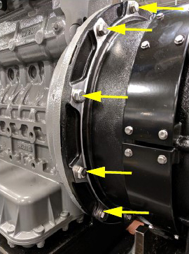
15.Starting with the lower bolts, remove the 3/8”-16 bolts / washers (12) that secure the generator to the engine.
NOTE: Although the generator torsional dampener and flywheel adapter plate will normally keep the generator coupled to the engine, even without the bolts, it is safest to remove the lower generator bolts first, in case the generator shifts and falls during bolt removal.
16.Lift the generator assembly (generator & support plate) off the unit frame and lower onto a stable work surface.
NOTE: Inspect the generator torsional dampener, bolt, and key as they are removed from the old generator and installed onto the new generator. Replace any components that are worn or damaged.
17.Remove the generator torsional coupler bolt / washer and pull off the torsional dampener.
18.Place the torsional dampener on the new generator shaft.
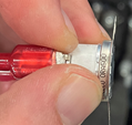
19.Insert the key into the keyway of the generator shaft. See Figure 6.1.
Figure 6.1 Generator Shaft Keyway
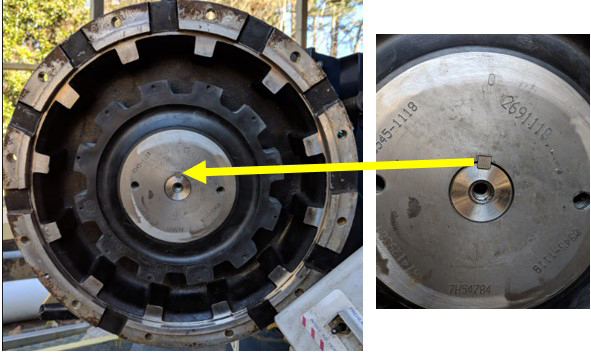
20.Apply Loctite 262 to the generator coupler bolt. Install with washer and torque to 28 ft-lbs (38 Nm). See Figure 6.2.
Figure 6.2 Generator Coupler Bolt
NOTE: In order to torque generator torsional dampener gear bolt, use a strap wrench or similar device to secure the dampener while torquing the bolt.
21.Remove the generator support plate from the old generator and install it onto the new generator.
22.With the torsional dampener and support plate installed on the new generator, lift and position the generator so that the generator mounting holes (12) are lined up with the engine mounting holes.
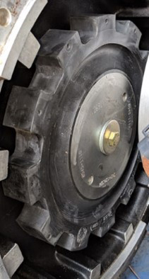
23.Insert two generator alignment bolts (2 1/2”) to temporarily align / secure the generator to the engine. Tighten the bolts enough so that the torsional dampener on the generator is touching the aluminum housing on the engine. Do not over tighten the alignment bolts, as they will bottom out on the engine bell housing. See Figure 6.3.
NOTE: Align the torsional dampener and aluminum housing by rotating either one to seat correctly.
Figure 6.3 Generator Alignment Bolt
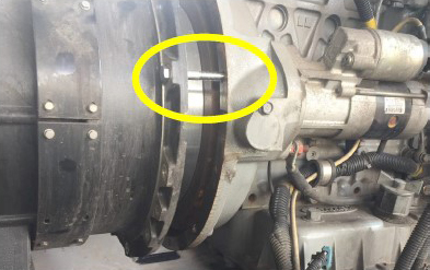
24.Once aligned, push the generator to fully seat the torsional dampener into the aluminum housing of the flywheel adaptor plate.
25.With the torsional dampener seated into the aluminum housing, the alignment bolts (2) can be removed, and the generator mounting bolts (12) can be reinstalled. Torque to 25 ft-lb (34 Nm). Install several mounting bolts to secure the generator before removing the alignment bolts. See Figure 6.4.
Figure 6.4 Generator Mounting Bolts
NOTE: Although the torsional dampener and mating surface of the generator will generally keep the generator coupled to the engine, even with all of the bolts removed, it is safest to start installation of the top generator bolts first, just in case the generator shifts.
26.With all of the generator mounting bolts secured, use the lift to raise the generator / engine in order to remove the support blocks under the engine.
27.Place the generator support plate mounting bolts (2) down into the generator support plate in order to line up the mounting bolt holes with the shockmounts.
28.Ensure that the large washers placed on the shockmounts and slowly lower the generator / engine so that the generator support plate holes line up with the shockmount holes.
29.Remove the generator support plate bolts and install the bolts / large washers from the bottom of the shockmounts through the generator support plate. Secure the bolts (2) with nuts, torque to 75 ft-lb (102 Nm).
30.Tighten the engine shockmount bolts, torque to 90 ft-lb (122 Nm).
31.Replace the lower radiator access panel and secure with bolts / washers (3).
32.Secure the battery charger cables to the bottom of the battery charger.
Observe proper polarity when installing the battery or connecting a battery charger, the negative battery terminal must be grounded. Reverse polarity may damage the charging system. When charging the battery in unit, isolate the battery by disconnecting the negative battery terminal first, then the positive. Once the battery has been charged, connect the positive battery terminal first, then the negative.
33.Secure the battery charger assembly to the unit frame.
34.Cut the wire-tie supporting the receptacle box to the unit frame and re-secure the receptacle box to the unit frame using bolts and washers (6). Make sure the receptacle wires are pulled through the access port in the frame and ensure that they will be accessible to splice with the generator wires.
35.Place two pieces of heat shrink tubing (1 large, 1 small) over each receptacle box wire.
36.Connect and butt splice the receptacle box harness wires with the new generator wires.
37.For each of the other five wires, heat shrink the small tubing first, and then the large tubing to ensure a watertight seal.
38.Neatly tape all wires together.
39.Replace and secure the wire harnesses onto the top of the generator, secure with the bolt.
40.Replace the truss and the truss brackets, secure the sides with the mounting bolts (2). See Figure 6.7.
NOTE: Installing the two back truss bolts first allows the truss assembly to be pulled forward slightly, making it easier to install the two front truss bolts.
41.Secure the center of the truss to the isolator by installing the nuts (2) and nut plate (1).
42.Connect the battery.
43.Re-install the top and side panel covers.
6.7.2Checking and Replacing Shockmounts
When a shockmount has been cut, split, abraded or has flared due to normal deterioration, it must be replaced. Damage to the mounts may not be visible when installed and under load from the component. To correctly inspect shockmounts, they must be removed.
Continued operation with failed shockmounts may result in engine or generator damage. When a shockmount has been cut, split, abraded or has flared due to normal deterioration, it must be replaced. Damage to the mounts may not be visible when installed and under load from the component. To correctly inspect shockmounts, they must be removed
6.7.2.1Generator Shockmount Replacement
1.Use the two lift eyes to lift and support the engine.
2.Remove shockmount hardware. See Figure 6.5.
3.Raise the generator just enough to remove the shockmounts.
4.Install new shockmounts.
5.Lower the engine enough to assemble hardware as shown and torque. See Section 6.7.3 for values.
6.Remove chains from the lift eyes.
Figure 6.5 Generator Shockmounts
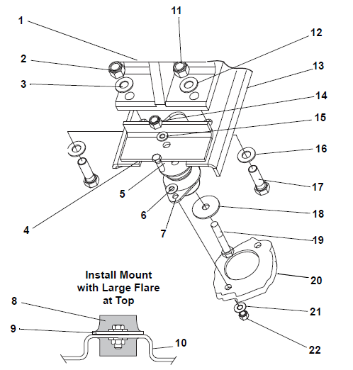
1)Generator
2)Lock-nut (5/8)
3)Flat Washer (5/8)
4)Support Plate
5)Screw (3/8)
6)Flat Washer (3/8)
7)Shockmount
8)Shockmount
9)Support Plate
10)Frame
11)Locknut (5/8)
12)Flat Washer (5/8)
13)Mounting Base
14)Lockout (1/2)
15)Flat Washer (1/2)
16)Flat Washer (5/8)
17)Screw (5/8)
18)Snubbing Washer
19)Screw (1/2)
20)Frame
21)Flat Washer (3/8)
22)Locknut (3/8)
- - - - -
6.7.2.2Engine Isolator / Shockmount Replacement
1.Use the two lift eyes to lift and support the engine.
2.Remove truss, unidrive isolator and all hardware. See Figure 6.7.
3.Remove all hardware. See Figure 6.6.
4.Raise the engine just enough to remove the shockmounts.
5.Inspect shockmounts and replace if required.
6.Lower the engine enough to assemble hardware as shown and torque as detailed in Section 6.7.3.
7.Remove chains from the lift eyes.
Figure 6.6 Engine Shockmounts

1)Shockmount
2)Snubbing Washer
3)Bolt
4)Lock Washer
5)Snubbing Washer
6)Shockmount
7)Flat Washer
- - - - -
Figure 6.7 Truss and Isolator
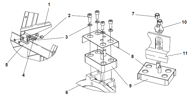
1)Truss
2)Bolt
3)Lock Washer
4)Flat Washer
5)Frame
6)Unidrive
7)Locknut
8)Heat Shield
9)Isolator
10)Nutplate
11)Truss
- - - - -
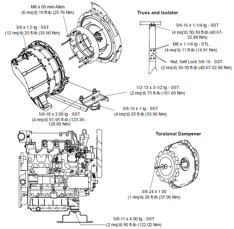
6.7.3Unidrive Torque Requirements
Extensive damage may occur if the proper hardware is not used and/or proper procedures are not followed when working with the unidrive assembly. Periodic inspection of hardware and bolt torque is recommended to ensure the integrity of the unidrive. Torque value and hardware requirements for unidrive assembly are detailed in Figure 6.8.
NOTE: SST is an abbreviation for 300 Series Corrosion Resistant Steel. Loctite #242 or an equivalent product should be used on ALL hardware as detailed in Figure 6.8.
Figure 6.8 Unidrive Torque Requirements
6.7.4Maintenance of Painted Surfaces
The unit is protected against the corrosive atmosphere in which it normally operates by a special paint system. However, should the paint system be damaged, the base metal can corrode. If the paint system is scratched or damaged, do the following:
1.Clean area to bare metal using a wire brush, emery paper or equivalent cleaning method.
2.Immediately following cleaning, spray or brush on a zinc rich primer.
3.After the primer has dried, spray or brush on finish coat of paint to match original unit color.