Description
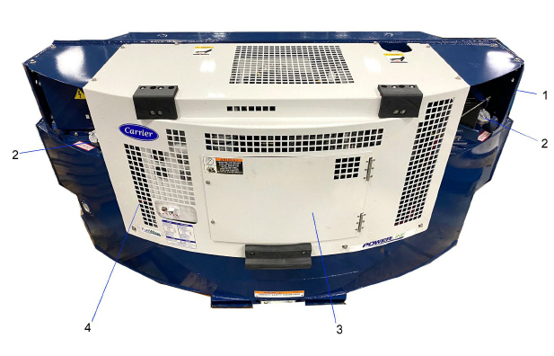
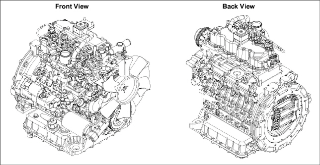
The Carrier Transicold model 69RG15 CARB diesel-driven generator set provides a constant electrical power supply for all-electric refrigeration units. The 69RG15 generator set is a a clip-on unit (Figure 3.1, Figure 3.2) mounted to the front of the container either by pin mounts located on the top channel or by optional clamp mounts located on either side of the generator set.
The generator set consists of a diesel engine directly connected to an alternating current generator and mounted in a structural steel frame. The engine is a vertical, in-line, four cylinder diesel manufactured by Kubota. The generator is a 15 kW, permanent, single winding, dual bearing type that supplies nominal 50/60Hz power.
Electrical controls are mounted in a control box with operating controls and gauges mounted on a control panel, which also serves as the control box cover. The control panel components are protected by a deflector assembly and control box door.
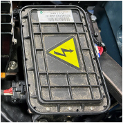
1)Unit Nameplate (Model, Serial, PID)
2)Fuel Cap
- - - - -
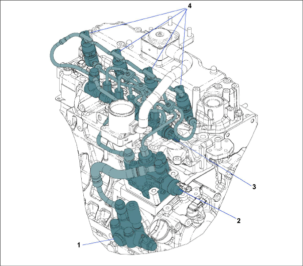
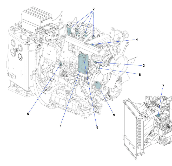
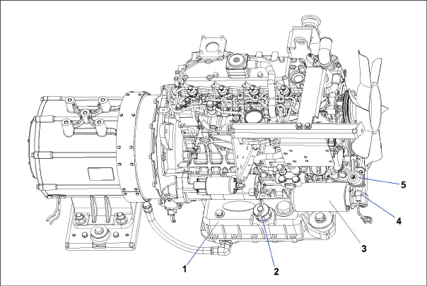
Figure 3.2 Generator Set - Covers Removed
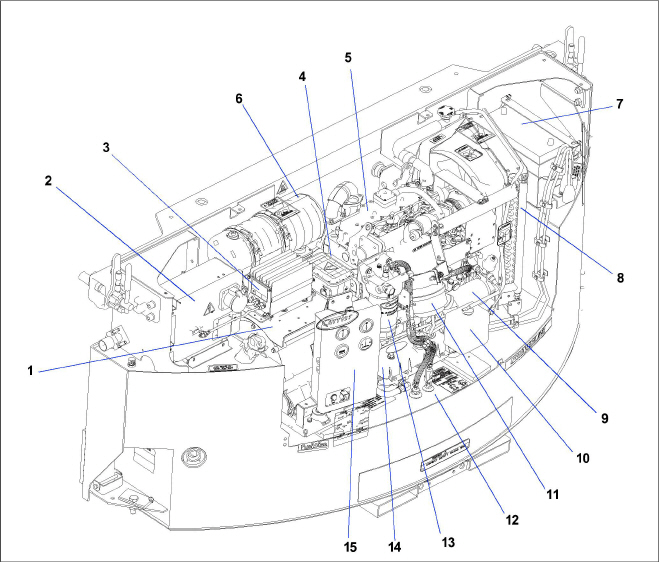
1)AC Generator
2)Receptacle Box
3)Battery Charger
4)Voltage Controller
5)Engine
6)Exhaust (DOC)
7)Battery
8)Radiator
9)Oil Filter
10)Coolant Recovery Bottle
11)Engine Air Cleaner
12)Fuel Tank
13)Fuel Filter / Water Separator
14)Starter
15)Control Panel and Control Box
- - - - -
3.2Configuration Identification
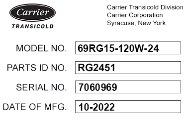
Generator set identification information is provided on a unit nameplate located on the side of the unit. The label provides the generator set model number, serial number and parts identification number (PID). The model number identifies the overall configuration, while the PID provides information on specific optional equipment and differences in detailed parts.
3.3Alternating Current Generator
The alternating current (AC) generator converts mechanical energy produced by the engine into electrical current. The AC generator bolts directly to the engine and supplies nominal 50/60Hz power based on the load requirement. Generator sets will start at 50Hz. Once the unit is running, the voltage controller (see Section 3.4) reads the voltage output of the generator and adjusts accordingly to keep voltage within ISO limits. As the container becomes loaded, voltage drops and current increases, causing the generator set to adjust speed based on power demand and ambient conditions. The unit typically runs at 50Hz and varies generator output via winding selection. The speed change to 60 Hz typically occurs when the ambient temperature is high and the unit is heavily loaded.
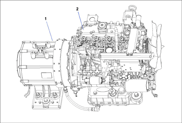
1)Generator
2)Engine
- - - - -
The voltage controller (VC), located on top of the AC generator, regulates the output voltage of the AC generator. Once the unit is running, the voltage controller (VC) will read the voltage output of the AC generator and adjust accordingly via two-speed and single winding control to keep the voltage within ISO limits (Table 3–3). The voltage controller is protected by two fuses (VCF1, VCF2) located in the receptacle box.
The engine (Figure 3.5) is a vertical, in-line four cylinder diesel engine that is directly connected to the AC generator. The engine is a Kubota V2403-CR series, which uses a diesel engine fuel injection control system for the precise metering and delivery of fuel into the engine combustion chamber.
The engine system consists of the following major components that are described in detail in this chapter.
•Engine Body. See Section 3.6
•Fuel System. See Section 3.7
•Intake and Exhaust System. See Section 3.8
•Lubrication System. See Section 3.9
•Cooling System. See Section 3.10
•Electrical System. See Section 3.11
Other resources related to the engine:
•Engine Specifications. See Section 3.15
•Troubleshooting Engine Symptoms. See Section 5.3
•Servicing Engine Components. See Section 6.3.
The engine body is the main part of the engine. It consists of cylinder related components, primary motion components and valve train mechanisms. Each of the parts are designed and assembled with passages for circulation of lubricating oil and coolant within the engine.
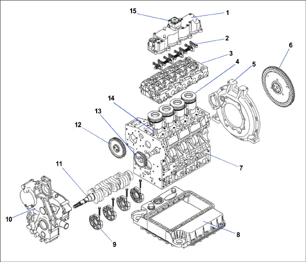
1)Cylinder Head Cover
2)Rocker Arm
3)Cylinder Head
4)Piston
5)Flywheel Housing
6)Flywheel
7)Crankcase
8)Oil Pan
9)Main Bearing Case
10)Gear Case
11)Crankshaft
12)Idle Gear
13)Camshaft with Cam Gear
14)Connecting Rod
15)Breather
- - - - -
The engine fuel system (Figure 3.7, Figure 3.8) is a common rail fuel system that injects a precise amount of atomized fuel into the engine cylinders. A common rail fuel system allows for improved efficiency and combustion, better atomization from higher fuel pressures and a reduction of emission pollutants. Fuel is pumped to the injectors for engine combustion. Surplus fuel is returned to the fuel tank after fuel injection.
Various parameters such as fuel pressure in the rail, coolant temperature, etc are transmitted from various sensors to an Engine Control Unit (ECU). See Section 3.7.9 for more details.
Figure 3.7 Fuel System Components - Carrier
1)Fuel Tank
2)Fuel Supply
3)Fuel Shutoff Valve
4)Fuel Pre-Filter Pump
5)Fuel Filter / Water Separator
6)Fuel Return
7)Fuel Tank Vent (2)
8)Fuel Fill Cap (2)
- - - - -
Figure 3.8 Fuel System Components - Kubota
1)Fuel Feed Pump
2)Fuel Supply Pump, High Pressure
3)Rail Assembly
4)Fuel Injectors (4)
- - - - -
See fuel system diagram, Figure 3.9, for reference.
Fuel exits the tank at low pressure and flows through the fuel shutoff valve to a pre-filter pump.
The pre-filter pump sends fuel to the fuel filter at a flow that allows for proper filter performance.
The fuel filter removes water and finer particles and includes a 12-volt fuel heater.
The low pressure fuel enters the fuel feed pump, where it is then sent to the high pressure supply pump.
The high pressure supply pump compresses the fuel to higher pressures and distributes to the rail assembly.
The rail assembly stores high pressure fuel and delivers fuel to the four injectors, 1 for each cylinder.
The injectors perform fuel injection into the combustion chamber based on a signal received from the Engine Control Unit (ECU).
Surplus fuel collects in the fuel overflow pipe and is returned to the fuel tank.
Figure 3.9 Fuel System Diagram
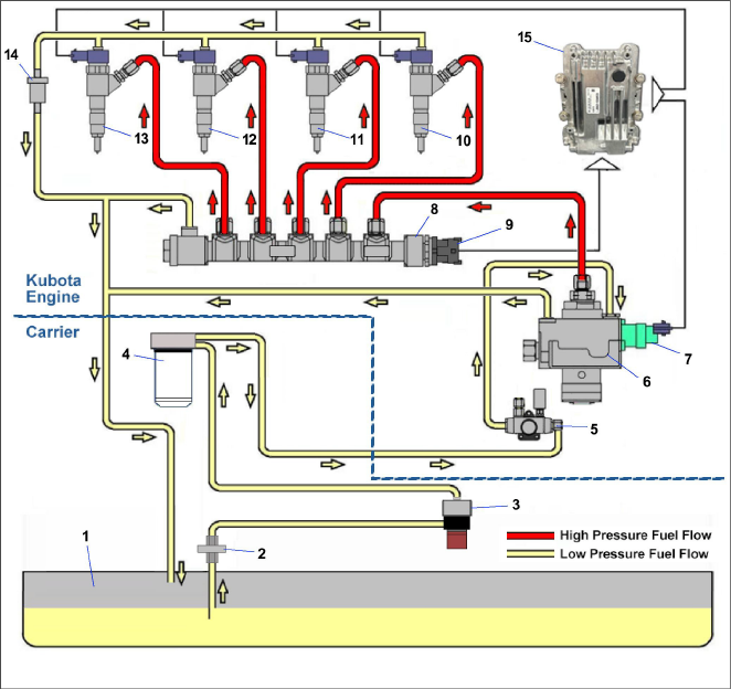
2)Fuel Tank Shutoff Valve
3)Pre-Filter Pump
4)Fuel Filter / Water Separator
5)Feed Pump
7)Suction Control Valve
8)Rail Assembly
9)Rail Pressure Sensor
10)Fuel Injector 1
11)Fuel Injector 2
12)Fuel Injector 3
13)Fuel Injector 4
14)Check Valve
15)Engine Control Unit (ECU)
- - - - -
The fuel tank is available in 120 gallon capacity. The tank is equipped with a fuel gauge, two fill caps and a fuel tank breathing vent valve. The tank supply and return lines are located at the front of the unit with a fuel shutoff valve on the supply line.
The pre-filter fuel pump sends fuel to the fuel filter at a flow that allows for proper filter performance.
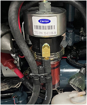
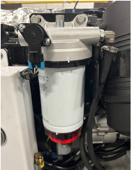
3.7.4Fuel Filter / Water Separator
The fuel filter (Figure 3.11) is a fuel particle filtration system that helps prevent premature injector and pump wear by delivering cleaner fuel to the engine. The fuel filter includes integral depth coalescing water separation, water-in-fuel visual float ring, drain valve assembly, supply air bleed and a fuel heater.
The fuel feed pump (Figure 3.12) supplies fuel to the high pressure supply pump mechanically. The fuel feed pump is equipped with a priming pump, which removes air through manual operation of the priming pump.
3.7.6High Pressure Supply Pump
The high pressure supply pump (Figure 3.13) pressurizes and supplies fuel to the rail assembly at more than twice the pressure of conventional pumps. The pump consists of a suction control valve (SCV), overflow valve, IO valve and zero delivery drain.
Figure 3.13 High Pressure Supply Pump (top view)
The engine side fuel camshaft rotates and during the lowering stroke a spring causes the plunger to lower. An optimal amount of fuel adjusted by the suction control valve (SCV) is suctioned through the IO valve and into the plunger chamber. During the lift stroke of the cam the plunger rises, pressurizes the fuel and supplies it through the IO valve to the rail.
When the pressure of fuel delivered from the feed pump rises above a prescribed amount, the overflow valve has a function of returning fuel to the tank. When fuel pressure increases and exceeds the force of the spring, the valve piston is pushed. The fuel then passes through the port provided in the valve body and returns to the fuel tank stabilizing the suction control valve (SCV) pressure and accurately adjusting the fuel flow.
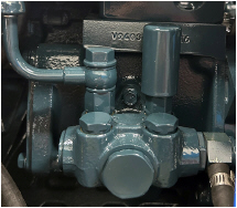
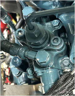
The rail assembly (Figure 3.14) stores high pressure fuel fed from the supply pump and while retaining the pressure, delivers fuel to the injectors for each cylinder. The rail assembly consists of a rail body, rail pressure sensor and pressure limiter.
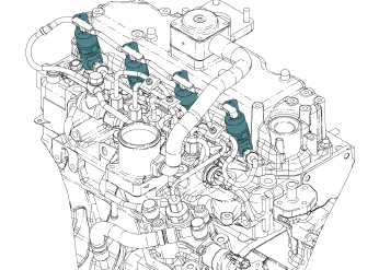
There are four injectors (Figure 3.15) that inject high pressure fuel from the rail into the combustion chamber. Injection is performed based on a signal received from the engine control unit (ECU) indicating fuel injection timing and fuel amount. See Section 3.7.9 for ECU details.
NOTE: The injectors are referred to as ENINJ1, ENINJ2, ENINJ3, ENINJ4 on the carrier system schematic.
There are three injections for every one combustion cycle:
•Pre Injection. A small amount is injected to reduce the effects of initial combustion and to lower nitrogen oxides and noise.
•Main injection. The highest amount of volume is injected, primarily for combustion.
•After injection. This is for combustion of unburned fuel.
In addition, a post injection is run for after treatment (not during combustion). The fuel is injected during the exhaust stroke to raise the temperature of the DOC to combust particulate matter.
A pressure limiter operates when the pressure inside the rail becomes excessively high (valve opens to return fuel back to the tank). Once the pressure drops, it acts to hold the pressure (valve closes).
The Engine Control Unit (ECU) controls the injection amount, timing, rate and pressure during fuel injection. The ECU consists of a case and electronics part mounting board, with operating software installed in the board. Control based on the ECU is performed by sending instructions to each actuator (suction control valve, individual injectors) based on input signals received from each sensor.
NOTE: The ECU is listed as ENCU on the carrier system schematic.
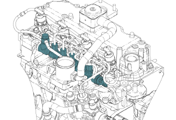
Figure 3.16 ECU with Related Actuators and Sensors
1)Engine Control Unit (ECU)
2)Fuel Injectors
3)Suction Control Valve
4)Rail Pressure Sensor
5)Crankshaft Position Sensor
6)Camshaft Position Sensor
7)Coolant Temperature Sensor
8)Atmospheric Pressure Sensor
9)Low Oil Pressure Switch
- - - - -
The following items are controlled by the ECU as control for a common rail system engine:
1.Fuel injection quantity control. The amount of fuel injected is determined using standard injection volume calculated based on engine state and operating conditions. A calibration value is added to this information through parameters such as coolant temperature.
2.Fuel injection timing control. The ECU controls injection timing through start of energization of the injectors. First the main injection timing is determined and next other injection timing such as pilot injections are set.
3.Fuel injection rate control. A pilot injection enables maintaining minimum initial fuel injection rate. This mitigates explosive initial combustion and reduces nitrogen oxides and noise.
4.Fuel injection pressure control. Based on engine load (final injection volume and engine speed), the engine ECU calculates the set fuel injection pressure. Calculated data is used to control the volume supplied by the supply pump as well as the fuel pressure in the rail.
3.7.9.1Suction Control Valve
The Suction Control Valve (SCV) is a proportional control valve that adjusts the amount of fuel delivered from the high pressure supply pump requested by the ECU. It is mounted on the side of the pump.
NOTE: This is referred to as the Engine Fuel Control Valve (ENFCV) on the carrier system schematic.
The Rail Pressure Sensor detects the fuel pressure inside the rail, converts this to an electronic signal and sends it to the Engine Control Unit (ECU) to provide optimal feedback control for the engine speed and load. This greatly improves the ability to raise the pressure at low speed and enables high-pressure injection from low speed ranges. It is mounted at the end of the rail assembly.
NOTE: This is referred to as the Engine Fuel Rail Pressure Sensor (ENFRP) on the carrier system schematic.
3.7.9.3Crankshaft Position Sensor
The engine crankshaft position sensor senses the pulsar hole on a flywheel and detects the angular position of the crankshaft. This sensor is a magnetic resistance element type sensor. It is mounted on the flywheel housing.
NOTE: This is referred to as the NE sensor in Kubota literature.
NOTE: This is referred to as the Engine Speed Sensor (ENSSN) on the carrier system schematic.
3.7.9.4Camshaft Position Sensor
The camshaft position sensor senses the teeth on a pulsar gear and detects the angular position of the camshaft. The pulsar gear has teeth at non-equal intervals. This sensor is a magnetic resistance element type sensor.
NOTE: This is referred to as the G sensor in Kubota literature.
NOTE: This is referred to as the Engine Camshaft Sensor (ENCS) on the carrier system schematic.
3.7.9.5Coolant Temperature Sensor
The coolant temperature sensor detects the temperature of the coolant inside the engine. When the engine coolant temperature changes, the resistance of the thermistor at the tip of the sensor changes. Once the resistance changes, the sensor output voltage changes and the output voltage signal of the sensor is sent to the ECU.
NOTE: This is referred to as the Engine Coolant Temperature Sensor (ENCT) on the carrier system schematic.
3.7.9.6Atmospheric Pressure Sensor
The atmospheric pressure sensor detects atmospheric (barometric) pressure and outputs a signal to the ECU. This sensor is built into the ECU and is not serviceable.
3.7.9.7Low Oil Pressure Switch
The low oil pressure sensor determines if the oil pressure is within the specified range while the engine is running.
NOTE: This is referred to as the Low Oil Pressure Switch (LOP) on the carrier system schematic.
3.8Engine Intake and Exhaust System
The air intake system supplies clean air to the engine. The exhaust system collects exhaust gases after combustion and discharges them to the atmosphere once after-treatment occurs.
Figure 3.17 Intake and Exhaust Flow
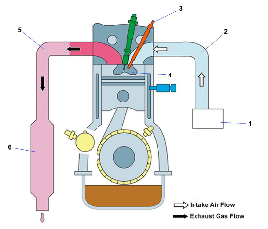
1)Air Cleaner
2)Intake Manifold
3)Glow Plug
4)Combustion Chamber
5)Exhaust Manifold
6)Diesel Oxidation Catalyst (DOC)
- - - - -
The engine air cleaner system (Figure 3.18) utilizes a filter element to filter the engine intake air. The air cleaner effectively removes contaminants from the air stream, resulting in prolonged engine life and reduced wear on all operating engine parts. When a dry element air filter is utilized, an air filter indicator is mounted on the air filter body to indicate when the filter element needs to be replaced.
Figure 3.18 Engine Air Cleaner
1)Air Cleaner, Filter
2)Air Inlet
3)Air Filter Indicator
4)Air Outlet
- - - - -
The intake manifold is mounted on the intake air side of the cylinder head. Its primary function is to distribute intake air to each cylinder. Air flows from the air cleaner filter to the intake manifold.
The glow plug warms intake air at the combustion chamber to help with starting the engine. There are four glow plugs, one for each combustion chamber. Glow plugs are activated when coolant temperature is sensed by the ECU to be 21°C (70°F) or less. See Section 8.5 for glow plug logic chart.
The exhaust manifold is mounted on the exhaust side of the cylinder head. The exhaust manifold is ducting that collects exhaust gases combusted in each cylinder and feeds this to the engine exhaust after-treatment system.
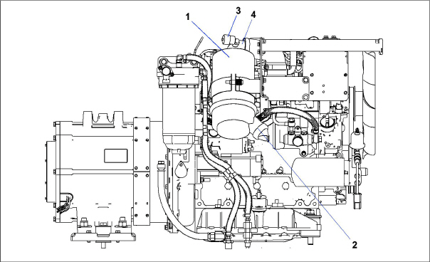
3.8.5Engine Exhaust After-Treatment System
The Diesel Oxidation Catalyst (DOC) burns particulate matter, such as soot, contained in the exhaust gas. A post injection occurs in the combustion chamber (not during combustion) to raise the temperature inside the DOC to combust particulate matter. In the chemical reaction that occurs, the particulate matter is converted from carbon monoxide to carbon dioxide and water. The carbon dioxide is released to the atmosphere.
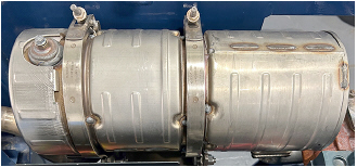
Figure 3.19 Diesel Oxidation Catalyst (DOC)
The engine lubrication system (Figure 3.20) supplies lubricating oil to the various moving parts in the engine. The main function is to enable the formation of a film of oil between moving parts, to reduce friction and wear.
The engine lubricating oil filter is mounted in a horizontal arrangement. The Oil Pressure Sender (OPS), located at the oil filter housing, senses lube oil pressure and transmits a signal to the Oil Pressure Gauge (OPG) located on the control panel (Figure 3.23). The Low Oil Pressure (LOP) switch opens when engine lubricating oil pressure is observed below 1.27 kg/cm.
Figure 3.20 Engine Lubrication System
1)Oil Pan
2)Oil Dipstick / Fill Cap
3)Oil Filter
4)Low Oil Pressure (LOP) Switch
5)Oil Pressure Sender (OPS)
- - - - -
The engine cooling system (Figure 3.21) uses extended life coolant and a radiator to keep the engine from overheating. The radiator transfers the heat from the engine coolant to the surrounding air. The water pump and the radiator cooling fan are belt-driven from the engine crankshaft. The Water Temperature Sender (WTS) is an engine protection device that monitors and regulates cooling water temperature.
Figure 3.21 Engine Cooling System
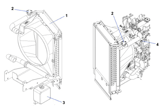
1)Radiator assembly
2)Radiator fill cap
3)Coolant recovery bottle
4)Water Temperature Sender (WTS)
- - - - -
The engine electrical system refers to the engine start circuit and the charge circuit. The starting circuit starts up the starter by means of the ignition switch (see Section 3.12.6) and starts the engine by turning the flywheel. The charge circuit generates electricity in the AC generator utilizing power when the engine is running and this is then used to power the battery charger, which powers the battery.
3.11.1Battery and Battery Charger
The battery provides 12 VDC power to the starter when starting the engine. It also provides the initial voltage for the glow plug until the unit starts. The battery is next to the radiator assembly. The solid state battery charger is powered by the generator and is located on top of the generator. The battery charger is protected by a 5 amp fuse in the receptacle box. The battery charger produces a tapered charge (40 amps maximum) and is designed not to overcharge the battery.
3.12Control Panel and Control Box Components
The control panel and control box (Figure 3.23) contain components required for monitoring and controlling the generator set unit.
Figure 3.23 Control Panel and Control Box
1)Water Temperature Gauge (WTG)
2)Oil Pressure Gauge (OPG)
3)Total Time Meter (TT)
4)Ammeter (A)
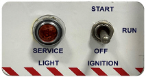
5)Engine Service Light (ESL)
6)Ignition Switch (IGN)
7)Starter Solenoid Relay (SSR)
8)Engine Speed Relay (ENSR)
9)Glow Plug Relay (GPR)
10)Engine Relay (ENGR)
11)Fuel Pump Relay (FPR)
13)Circuit Breaker (CB-3)
14)Circuit Breaker (CB-4)
- - - - -
The water temperature gauge (WTG) displays cooling water operating temperature as reported by the water temperature sender (WTS), see Figure 3.21. Once the unit has achieved normal running temperature, the coolant temperature is between 82 - 96°C.
The oil pressure gauge (OPG) displays normal operating engine oil pressure as reported by the oil pressure sender (OPS) on the oil filter housing, see Figure 3.20. Normal oil pressure is 43 to 64 psi (3.0 to 4.5 kg/cm2).
The total time meter (TT) calculates the total hours the unit has been running, which provides an accurate readout of accumulated engine running time. This data can be used to establish proper maintenance schedules, refer to Table 6–2.
The ammeter (A) indicates the rate of charge or discharge of the battery charging system. The battery charging system is composed of the battery and the battery charger, either solid state or alternator.
The engine service light (ESL) is illuminated to indicate that service is needed for the engine as reported by the engine control unit (ECU).
The ignition switch (IGN) is a momentary switch that has OFF/RUN/START positions.
•OFF: In the OFF position, power supply is turned OFF and the engine is stopped.
•RUN: In the RUN position, all electrical equipment is operational. The engine is in operating position. Pre-heat of combustion chamber.
•START: When held in the START (ignition) position, the starter motor solenoid is energized, which allows the starter motor to crank the engine. The switch is released to the RUN position once the engine has started.
The starter solenoid relay (SSR) switches on the current that activates the starter solenoid when the ignition switch is held in the START position.
The engine speed relay (ENSR) allows the engine speed to be run at either 1500 or 1800 rpm. The engine will run at 1500 rpm unless the voltage controller senses low voltage and then a signal is sent to adjust the speed to 1800 rpm.
The fuel pump relay (FPR) powers the pre-filter fuel pump. An in-line fuse (F4) is between the relay and the pump.
The engine relay (ENGR) or main relay helps to ensure that the engine control unit (ECU) gets the power it needs to run and function as intended.
The glow plug relay (GPR) switches on the current that turns the glow plug on to help heat up the engine. Glow plugs are activated when coolant temperature is sensed by the ECU to be 21°C (70°F) or less. See Section 8.5 for glow plug logic chart.
CB-2 trips at 30 amps to protect the ignition and starter circuits.
CB-3 trips at 50 amps to protect the glow plug (GP) circuit.
CB-4 trips at 30 amps to protect the 12 volt supply circuit.
The receptacle box (Figure 3.24) contains components required for monitoring and controlling the genset unit.
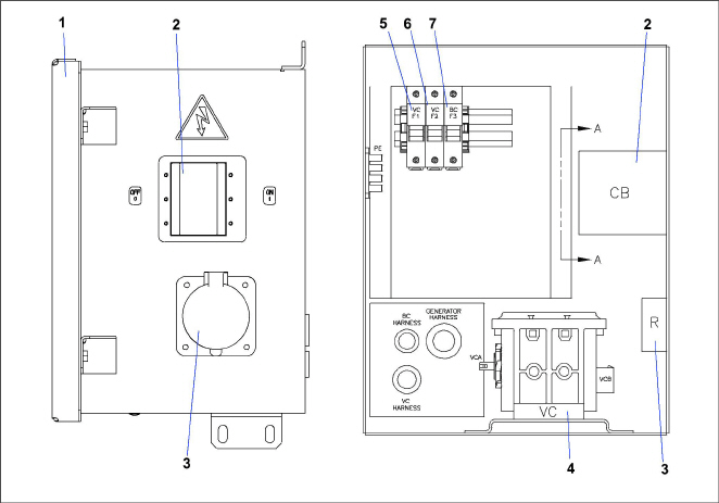
1)Access Cover
2)Circuit Breaker (CB1) Genset
3)Receptacle
4)Voltage Controller (VC)
5)Voltage Controller Fuse (VCF1)
6)Voltage Controller Fuse (VCF2)
7)Battery Charger Fuse (BCF3)
- - - - -
Safety devices, such as circuit breakers, fuses, and safety switches, protect system components from damage.
Safety device specifications are provided in Table 3–1.
Engine |
||
Unsafe Condition: |
Low engine lubricating oil pressure |
|
Safety Switch |
Low oil pressure (LOP) switch - Automatic reset |
|
Switch Setting |
Opens below 18 psig (1.27 kg/cm2) |
|
Unsafe Condition: |
High engine cooling water temperature |
|
Safety Switch |
Engine Coolant Temperature (ENCT) sensor |
|
Switch Setting |
Opens at 120°C (248°F) |
|
Unsafe Condition: |
Excessive current draw by the ignition and starter circuits. |
|
Safety Switch |
Circuit breaker (CB-2) - Automatic reset |
|
Switch Setting |
Trips at 30 amps |
|
Unsafe Condition: |
Excessive current draw by the ignition switch, starter switch, total time meter (TT), water temperature gauge (WTG) and oil pressure gauge (OPG). |
|
Safety Switch |
Fuse 1, 2, 3 (replace) |
|
Switch Setting |
Trips at 5 amps |
|
Pre-Filter Fuel Pump |
||
Unsafe Condition: |
Excessive current draw on the pre-filter fuel pump |
|
Safety Switch |
Fuse F4 |
|
Switch Setting |
Trips at 5 amps |
|
Glow Plug |
||
Unsafe Condition: |
Excessive current draw on the glow plug (GP) circuit |
|
Safety Switch |
Circuit breaker (CB-3) - Automatic reset |
|
Switch Setting |
Trips at 50 amps |
|
Battery Charger |
||
Unsafe Condition: |
Excessive current draw on 12 volt supply circuit. |
|
Safety Switch |
Circuit breaker (CB-4) - Automatic reset |
|
Switch Setting |
Trips at 30 amps |
|
Unsafe Condition: |
Excessive current draw on 460 volt feed circuit |
|
Safety Switch |
Fuse BCF3 |
|
Switch Setting |
Trips at 5 amps |
|
Generator |
||
Unsafe Condition: |
Excessive current draw by load |
|
Safety Switch |
Circuit breaker (CB-1, 460 volt) - Manual reset |
|
Switch Setting |
Trips at 26 amps (460 VAC) |
|
Voltage Controller |
||
Unsafe Condition: |
Excessive current draw on 460 volt feed circuit |
|
Safety Switch |
Fuses VCF1, VCF2 |
|
Switch Setting |
Trips at 5 amps |
|
Capacity: |
Nominal tank size: 120 gallon |
|
Fill capacity: 120 gallon |
||
Draw capacity: 119 gallon (Allows for DOT required 5% vapor space) |
||
Unit Weight: |
Engine (Dry) without accessories: 1875 lb (851 kg) approximate |
|
Output: |
15 KW, 18.75 KVA, 0.8 pf KW |
Output Voltage: |
400-500 VAC @ 60 Hz; 360-460 VAC @ 50 Hz |
Speed: |
1800 RPM @ 60 Hz; 1500 RPM @ 50 Hz |
Weight: |
267 lb (121 kg) |
Part Number: |
54-00378-20 |
Model |
V2403-CR-E4 |
|
Cylinders (Number): |
Four |
|
Engine Type |
Vertical, water-cooled, 4-cycle diesel |
|
Bore x Stroke: |
87 x 102.4 mm (3.43 x 4.031 in.) |
|
Total Displacement: |
2.434 liters (148.5 cubic in.) |
|
Direction of Rotation |
Counter-clockwise (viewed from flywheel side) |
|
Firing Order: |
1-3-4-2 |
|
Compression Ratio: |
18.1 to 1 |
|
Starting System |
Electric starting with starter |
|
Starter Motor |
12V, 2.0 kW |
|
Starting Support |
Glow plug in combustion chamber Glow plug amperage: Approximately 12 amps at 12 VDC Glow plug resistance (cold): Approximately 1 ohms |
|
Weight (Dry): |
487 lb (221 kg) Included ATU, excluded cooling fan |
|
Oil Pressure |
Oil pressure at idle speed: •Service specification: More than 14 psi (1.0 kg/cm2) •Service limit: 7 psi (0.5 kg/cm2) Oil pressure at rated speed: •Service specification: 43 to 64 psi (3.0 to 4.5 kg/cm2) •Service limit: 36 psi (2.5 kg/cm2) |
|
Oil Pressure Switch |
Working pressure: 7 psi (0.5 kg/cm2) |
|
Oil Sump Volume |
15.0 US quarts (14.2 L) |
|
Oil Level Indicator |
Dipstick in oil pan or fill cap NOTE: To check oil level on engines with the dipstick mounted in the fill cap, remove the cap and wipe the dipstick clean. Insert the cap back onto the oil fill tube, then remove to check level. It is not necessary to screw the cap back into the fill tube when checking level. DO NOT add oil if level is within the “safe” range. If needed, add oil to bring level within the “safe” range. Screw cap fully into fill tube after checking level. |
|
Lube Oil Specification |
Use a heavy duty lubricating oil conforming to American Petroleum Institute (API) Service Classification CK-4 or better. |
|
Lube Oil Viscosity |
For outdoor temperatures -18° to 7°C (0 to 45°F): SAE: 5W30 For outdoor temperatures above 7°C (45°F): SAE: 10W30 or 15W40 |
|
Fuel Specifications |
Since KUBOTA diesel engines of less than 56 kW (75 hp) utilize EPA Tier 4 and Interim Tier 4 standards, the use of ultra low sulfur fuel is mandatory for these engines, when operated in US EPA regulated areas. Therefore, use Ultra Low Sulfur Diesel (ULSD) or diesel with < B5 (5% biodiesel) |
|
Fuel Heater Thermostat (FHT) |
Thermostat On Temperature: ≤ 3 ± 5°C (37.4 ± 9°F) Thermostat On Temperature: ≥ 21 ± 7°C (69.8 ± 12.6°F) FH Power Consumption: 225 W 10%/-20% at 20 °C (-4°F) at 12VDC |
|
Fuel Pump, Pre-Filter |
Shut off pressure: 9 to 11.5 psig (0.63 to 0.81 kg/cm2) Maximum operating fuel temperature: 76°C (170°F) @ 14 VDC, 6 psi back pressure, 82°C (180°F) ambient. |
|
Fuel Pump. Feed |
Maximum discharge pressure: 72.5 psig (5.10 kg/cm2) |
|
Fuel Pump, High Pressure Supply |
Rail pressure (at idling): 25 to 30 mPa; 260 to 300 kgf/cm2; 3700 to 4300 psi Rail pressure (at rated speed, no load): 60 to 65 MPa; 620 to 660 kgf/cm2; 8700 to 9400 psi |
|
Fuel Pressure Limiter |
Valve opening pressure: Approximately 200 MPa; 2039 kgf/cm2; 29000 psi Valve closing pressure: Approximately 50 MPa; 510 kgf/cm2; 7260 psi |
|
Fuel Injector |
Operating voltage: 110 V Operating pressure range: 30 to 160 MPa; 306 to 1630 kgf/cm2; 4360 to 23200 psi |
|
Crankshaft Position Sensor |
Operating voltage: 5V Number of pulsar holes at flywheel: 56 |
|
Camshaft Position Sensor |
Operating voltage: 5V Number of pulsar gear teeth: 3 |
|
Cooling System: |
Capacity: 6 us quarts (5.68 liters) |
|
Anti-Freeze: Extended Life 50/50 mix of Ethylene Glycol & Water |
||