3.1Engine Emission System (EES) Overview
In a diesel engine exhaust system, unburned diesel fuel results in soot accumulation. This can cause clogging in the filter which in turn causes engine exhaust back pressure to become too high. The Engine Emission System (EES), is an optional system that removes most of the soot particles from the exhaust. By removing the soot particles, cleaner air is discharged out of the exhaust system during operation and back pressure is reduced. The EES also functions as the muffler when installed and reduces the exhaust related noise emitted from the unit.
The process of burning off the particulate matter in the EES is called Regeneration. This is where temperature is increased to a level that oxidizes the captured soot, leaving only (fine) inorganic ash and significantly reducing back pressure. Refer to Section 3.7 for a further explanation of Regeneration.
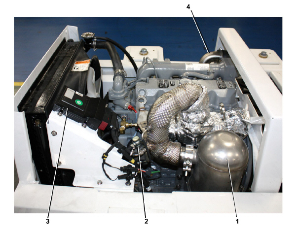
The major components of the ESS are the Exhaust System, Fuel Injector (Doser), Emissions Control Module (ECM), and Air Control Valve (ACV). Refer to Figure 3.1 for component locations.
Figure 3.1 Engine Emission System (EES) Components
3)Emissions Control Module (ECM)
- - - - -
3.2.1Diesel Oxidation Catalyst (DOC)
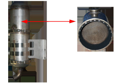
Exhaust flows through the Diesel Oxidation Catalyst (DOC), Figure 3.2, for initial filtration. Fuel is injected into the DOC to increase temperatures in the Diesel Particulate Filter (DPF) during regeneration. Refer to Section 3.7 for a description of how regeneration works. There are no service requirements for the DOC.
Figure 3.2 Diesel Oxidation Catalyst (DOC)
3.2.2Diesel Particulate Filter (DPF)
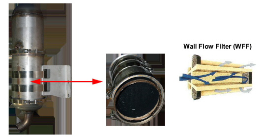
The Diesel Particulate Filter (DPF), Figure 3.3, traps particulate matter in a filter but allows exhaust gas to pass through. The DPF uses a Wall Flow Filter (WFF) design, which allows exhaust gases to pass through micro-porous walls. Particles of diesel soot and other debris is removed from the gas stream by filtration, but soot remains trapped in the DPF. As the amount of soot increases in the DPF, the back pressure in the exhaust increases as well. When the back pressure reaches a predetermined level, regeneration will occur to convert the captured soot into inorganic ash. Refer to Section 3.7 for a description of how regeneration works. The DPF requires periodic ash removal and filter cleaning. Refer to Section 6.4 for DPF Cleaning procedure.
Figure 3.3 Diesel Particulate Filter (DPF)
3.3Fuel Injector (Doser) Description
The Fuel Injector (Doser), Figure 3.4, sprays a small amount of fuel into the exhaust. The Doser helps raise exhaust temperatures during active regeneration when the engine is too lightly loaded for passive regeneration to occur. During active regeneration, the Doser valve injects a fine mist of fuel into the exhaust stream, where it then ignites on the surface of the DOC to raise the exhaust temperature and oxidize the particulate matter in the DPF. Automatic regeneration is initiated by the Emissions Control Module (ECM). Refer to Section 3.7 for a description of how regeneration works.
Coolant from the generator set radiator is supplied to the Doser to remove heat.
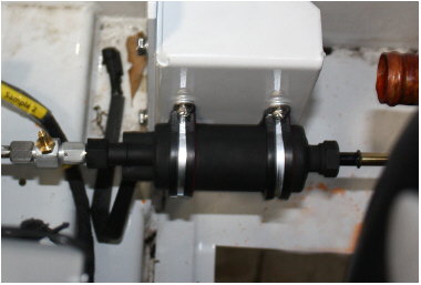
The EES Fuel Pump, Figure 3.5, taps into the generator set fuel tank supply in to pump fuel directly to the Doser during DPF regeneration. An in-line fuel filter / water separator is located between the pump and Doser.
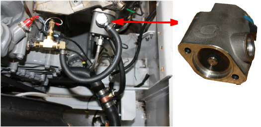
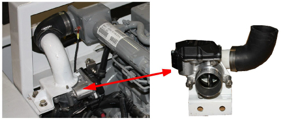
3.4Air Control Valve (ACV) Description
The Air Control Valve (ACV), Figure 3.6, restricts engine intake air to raise exhaust temperatures. It is a normally-open valve that is located on the engine air intake hose. When the DPF requires regeneration and exhaust temperature is very low (for example, during minimal engine loading and/or extremely cold weather), the ACV is used for active-assist regeneration. During active-assist regeneration, the ACV changes the air-to-fuel ratio in order to raise exhaust temperatures high enough for the doser to activate and regenerate the DPF. Refer to Section 3.7 for a description of how regeneration works.
Figure 3.6 Air Control Valve (ACV)
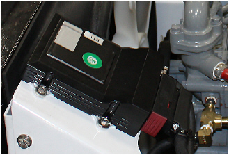
3.5Emissions Control Module (ECM) Description
The Emissions Control Module (ECM), Figure 3.7, monitors the EES parameters, using an internal back pressure sensor, along with temperature sensors mounted in three locations of the exhaust system. Based on the parameters, the ECM will initiate automatic regeneration when needed. Further diagnosing with the ECM requires the ECM Service Tool software. Refer to ECM Service Tool chapter for procedures.
Figure 3.7 Emissions Control Module (ECM)
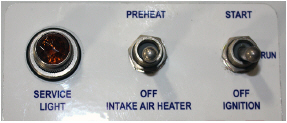
The ECM will signal to the service light, Figure 3.8, as part of alarm notification. A unit with an illuminated service light indicates immediate service is needed, and will continue to operate for up to 250 hours in order to protect load and allow adequate time for delivery. After 250 hours, the unit will shut down until the EES is repaired.
The temperature sensors monitor unit operation and report back to the ECM.
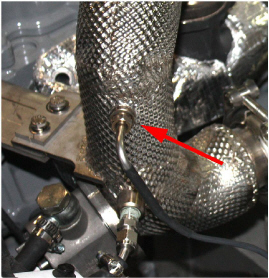
3.6.1Exhaust Inlet Temperature Sensor (ESEIT)
The Exhaust Inlet Temperature Sensor (ESEIT), Figure 3.9, monitors temperature entering the DOC. It is located just before the Doser and DOC. This temperature is directly dependent upon engine load and determines which type of regeneration is needed. When upstream temperatures are high enough (during high engine load), passive regeneration will occur. Refer to Section 3.7 for a description of how regeneration works.
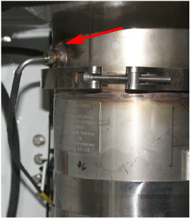
3.6.2Filter Inlet Temperature Sensor (ESFIT)
The Filter Inlet Temperature Sensor (ESFIT), Figure 3.10, monitors exhaust temperature entering the DPF. It is located after the DOC and before the DPF. This temperature data is utilized to control and maintain regeneration temperature at approximately 1112 °F (600°C). This temperature is maintained by injecting fuel into the system (active regeneration), or in some cases, using the ACV to restrict engine air intake (active-assist regeneration).
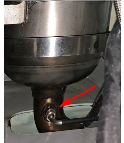
3.6.3Filter Outlet Temperature Sensor (ESFOT)
The Exhaust Outlet Temperature Sensor (ESFOT), Figure 3.11, monitors exhaust temperature leaving the DPF. It is located after the DPF and before the tail pipe. This temperature data is utilized to verify that the regeneration process is being properly controlled.
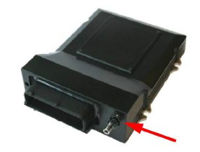
3.6.4Back Pressure Sensor (ESFP)
The Back Pressure Sensor (ESFP) measures back pressure at the upstream piping. It is located inside the ECM module. As the DPF gets filled with soot, back pressure will increase. The ESFP verifies that the regeneration process is being controlled properly.
Figure 3.12 Back Pressure Sensor (ESFP)
To treat the diesel soot that gets captured in the DPF, a process called regeneration is utilized. During regeneration, the temperature in the DPF is increased to a level that oxidizes the captured soot, leaving only (fine) inorganic ash and significantly reducing back pressure. Regeneration is aided by the Diesel Oxidation Catalyst (DOC) which raises the temperature of the exhaust entering the DPF. Higher exhaust temperatures improve the regeneration process in the DPF. The target exhaust temperature for regeneration is 1112°F (600°C).
A regeneration generally takes 15 to 20 minutes and may occur 1 to 3 times per day depending on conditions.
The EES will initiate a regeneration cycle when the following conditions are met:
•Back pressure in the exhaust reaches 24 in/H2O (6kPa) in low speed and 36 in/H2O (9kPa) in high speed.
•Automatic regeneration initiated every 12 hours of run time, or for 6 hours of run time if temperatures are below 32°F (0°C) at the Emissions Control Module (ECM).
A manual regeneration can be initiated through the ECM Service tool. Refer to Section 4.3 for procedures.
The three phases of regeneration are explained below:
Condition: Engine exhaust temperature is above 662°F (350°C).
Description: During Passive Regeneration, exhaust temperatures are hot enough to start an exothermic reaction in the DOC without assistance. Only the DOC and DPF are required. Passive Regeneration saves fuel by extending intervals between Active or Active Assist Regenerations.
Condition: Engine exhaust temperature is in range of 446° to 662°F (230° to 350°C).
Description: During Active Regeneration, fuel is injected into the exhaust system to raise exhaust temperatures hot enough to start a reaction in the DOC. Fuel is injected into the upstream pipe by the Doser and then catalyzed in the DOC, which actively increases the exhaust temperature entering the DPF.
Condition: Engine exhaust temperature is below 446° (230°C).
Description: During Active Assist Regeneration, the Air Control Valve (ACV) restricts engine air intake, which changes the air-to-fuel ratio and increases the exhaust temperature entering the DOC. Once the exhaust temperature reaches the level required for Active Regeneration, the Doser injects fuel into the upstream pipe.
After regeneration is complete, the exhaust temperature will be allowed to return to its normal state. All temperature data gets sent to the ECM. The ash that remains in the DPF after regeneration is only a fraction of the original mass; the reduced mass allows back pressure to return to near non-EES values. However, as ash continues to accumulate in the DPF, the base back pressure will continue to rise. Refer to Maintenance Schedule, Section 6.2, to see intervals for cleaning DPF.