Section 6
When fitted with a EES, the engine should be maintained and serviced as per service recommendations in the UG15 Generator Set Operation and Service Manual (T-360).
Maintenance and repair records must be maintained and submitted when requesting warranty for the EES. Records include maintenance history including engine hours, repair records including engine hours and any documented observations such as oil consumption trends, fuel consumption trends, and smoke emissions.
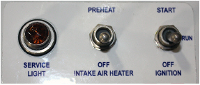
An illuminated service light, Figure 6.1, will indicate immediate service is needed. A unit with an illuminated service light will continue to operate for up to 250 hours in order to protect load and allow adequate time for delivery. After 250 hours, the unit will shut down until the EES is repaired.
The ECM Service Tool is diagnostic software that can test the functionality of individual EES components initiate regeneration, display alarm codes, provide current sensor readings. retrieve data from the ECM, and more. Further diagnosis with the ECM requires the following tools:
•ECM CAN Adapter: 07-00533-01
•ECM Service Tool software version 2.0.28.
Detailed information for ECM Service Tool instructions can be found in Section 4.
During the EES preventative maintenance service, the DPF assembly should be removed and cleaned to remove all accumulated ash. Ash is considered a hazardous material and must be collected using either a commercially available cleaning system or using a vacuum with a HEPA filter.
Follow the ash handling guidelines as prescribed by CARB at: www.arb.ca.gov/diesel/.
Procedure:
1.Initiate a manual regeneration to oxidize accumulated diesel soot from the exhaust. Refer to Section 4.3.
2.Shut down the engine and allow the DPF assembly to cool.
3.Disconnect the negative battery terminal and perform a lock-out / tag-out of the negative battery cable.
4.Remove the DPF module from the generator set.
5.Disassemble the DPF filter section and the DOC.
6.Remove ash from the DPF filter using either a commercially available cleaning system or a vacuum with a HEPA filter.
7.Using a new gasket (30-00510-63), reassemble the DPF filter section to the DOC. Tighten the v-clamp to specified torque. Refer to Installation Instructions for specified torques.
8.Reinstall the DPF assembly, with new inlet gasket, into the unit.
9.Properly align and tighten all clamps to specified torques. Refer to Installation Instructions for specified torques.
10.Remove lock-out / tag-out devices.
11.Reconnect negative battery cable to negative battery terminal.
12.Start the unit in Engine mode and initiate a regeneration. Check back pressure readings on the ECM Service Tool. Refer to Section 4.5. If back pressure reading is higher than 120 in/H2O (30 kPa), then the filter may require additional cleaning or possible replacement.
13.If back pressure reading is higher than 120 in/H2O (30kPa), then filter may require additional cleaning, or possible replacement.
6.5Carb Registration and System Labeling
The DPF needs to be registered with CARB using the ARBER website. At any point in time that the DOC is replaced in the EES, re-registration with CARD is required.
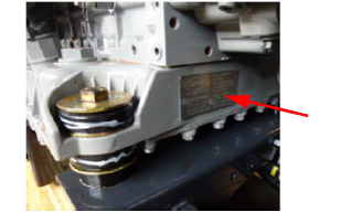
When the Filter Assembly, including DOC and DPF, is installed, a CARB label is provided for each component (Refer to Figure 6.2). The CARB label will contain relevant information about filter substrate name, serial number and date of manufacture. The CARB label for DOC is placed on the DOC itself, but a duplicate is also provided to place on the generator set unit, on the front of the oil pan.
Figure 6.2 CARB Labels for DOC and DPF
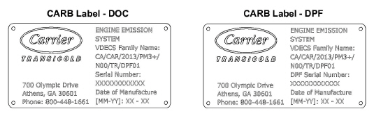
Figure 6.3 CARB Label Placement Location