Section 5
SERVICE AND PREVENTATIVE MAINTENANCE
This section covers service for the generator set and general engine service. Refer to the Kubota engine workshop manual 62-10865, Section 1.1, for additional engine servicing.
Beware of moving poly V-belt, belt driven components and hot exhaust components.
5.2Preventative Maintenance Schedule
A tabular listing of the recommended preventative maintenance activities and schedule is provided in Table 5–1.
Units have mineral oil installed from the factory - change lubricating oil and filters after the first 2000 hours of service or at the end of the first year, whichever comes first.
Oil changes after the first 2000 hour service, or 1 year:
•If using mineral oil, oil changes should continue every 2000 hours of service or every 1 year, whichever comes first.
•If using specified synthetic lubricating oil and OEM extended life oil filter, oil changes should be completed every 4000 hours of service, or every two years, whichever comes first.
1 Pre-trip maintenance checks should be carried out prior to any use of the unit (1-15 and 31-36).
2 2000 hour maintenance checks should be carried out annually or every 2000 hours, whichever comes first.
3 4000 hour maintenance checks should be carried out every two years or every 4000 hours, whichever comes first.
When replacing the battery, determine whether the unit was supplied with a mat in the battery tray. If so equipped, the mat must also be replaced.
5.4Engine Service and Components
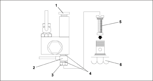
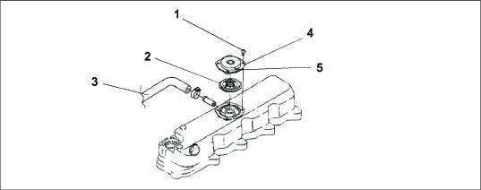
The unit is equipped with a mechanical fuel pump (see Figure 5.1) mounted on the engine next to the injection pump.
Figure 5.1 Mechanical Fuel Pump
1)Manual Priming Pump
2)Banjo
3)Nut
4)Copper Rings
5)Filter
6)Nut
- - - - -
The fuel system is a closed circuit which will require bleeding if loss of fuel has occurred. To fill and bleed the system, do the following:
1.Turn the (red) fuel bleed valve (see Figure 2.5) counterclockwise until fully opened.
2.Turn the top of the manual priming pump counter-clockwise to unlock it, and then hand pump the manual plunger until a positive pressure (resistance) is felt. This will indicate fuel flow.
3.Depress and turn the top of the manual priming pump clockwise to lock in place.
4.Start the engine (see Section 2.4).
5.When the engine is running properly, turn the fuel bleed valve clockwise until fully closed.
5.4.2Servicing Fuel Pump Internal Filter
The internal fuel filter may become plugged or restricted with foreign particles or wax, which can develop if the wrong grade of fuel is used or untreated fuel is used in cold weather, contaminating the fuel. If the internal filter is plugged, the engine will lose power. Therefore, the filter must be cleaned on a regular basis. The quality of the fuel will affect the filter cleaning schedule (see Section 5.2).
1.Turn the nut counter-clockwise to loosen and remove.
2.Remove the banjo fitting and let it hang loose.
3.Turn the filter counter-clockwise and remove. Check and clean.
4.To install, reverse steps 1 through 3.
The fuel filter is located on the generator set frame (see Figure 2.5).
1.To replace the fuel filter, loosen and remove the filter housing.
2.Lightly oil new gasket with lube oil.
3.Replace the filter.
If the generator set is equipped with the fuel filter bowl assembly, when replacing the fuel filter, a new fuel filter O-ring should be oiled and replaced, and then the clear bowl should also be tightened to 24 N-m.
1.Loosen bowl by turning counter-clockwise.
2.To renew, remove in-line fuel strainer. Check and clean, and replace.
To ensure adequate cooling, the radiator must be clean, externally and internally. To service the cooling system, do the following:
1.Remove all foreign material from the radiator coil by reversing the normal air flow. Compressed air or water may be used as a cleaning agent. It may be necessary to use warm water mixed with any good commercial dishwasher detergent. If a detergent is used, rinse coil(s) with fresh water.
2.Drain coolant completely by opening the drain cock and removing the radiator cap.
Never pour cold water into a hot engine.
3.Close the drain cock and fill the system with clean, untreated water to which between 3% and 5% of an alkaline base radiator cleaner should be added; 170 grams (dry) = 151 grams to 3.8 liter of water.
4.Run the engine 6 to 12 hours and drain the system while warm. Rinse the system three times after it has cooled down. Refill the system with water.
Use only ethylene glycol, anti-freeze (with inhibitors) in the system. Use of glycol by itself will damage the cooling system.
5.Run the engine to operating temperature. Drain the system again and fill with treated water / anti-freeze (see above Caution statement).
The primary oil filter is located near the radiator fan (see Figure 2.10).
1.After warming up the engine, stop the engine, remove the drain plug from the oil reservoir and drain engine lube oil.
2.Replace filters. Lightly oil the gasket on filter before installing.
3.Add lube oil (see Table 2–4).
4.Warm up the engine and check for leaks.
5.4.7Servicing Low Oil Pressure Switch
1.Remove the harness connection from the Low Oil Pressure Switch (LOP).
2.Remove the pressure switch from the engine.
3.Apply Teflon thread sealer to the threads of the new LOP switch.
4.Install the new LOP switch.
5.Reconnect harness connection to the low oil pressure switch.
1.The engine speed is electronically controlled.
Do not attempt to adjust engine speed.
5.4.9Replacing the Engine Speed Sensor
1.Disconnect the plug to the sensor.
2.Remove the bolt securing the sensor to the housing.
3.Remove the sensor from the housing.
4.Clean the recess in the housing to ensure that the sensor seats properly when re-installed.
5.Re-install the sensor, replace the securing bolt and connect the plug to the sensor.
Beware of moving poly V-belt and belt driven components.
Beware of pinch points.
A frayed, cracked or worn poly V-belt must be replaced. After installing a new belt, check the adjustment after running the unit for three or four hours. This will allow for the initial stretch, which is common on new belts. Once this initial stretch has taken place, the belt should be checked at regular intervals.
The poly V-belt is driven by a sheave on the engine crankshaft. Its two functions are: (1) to drive the radiator fan and (2) to drive the water pump. To replace the poly V-belt, perform the following steps:
1.Using the proper size socket, slowly rotate the crank on the crank pulley nut. At the same time, use a flat, blunt object to guide the belt off the crank pulley towards radiator. Be careful not to damage grooves on the pulley.
2.Replace the poly V-Belt by positioning the belt on the water pump pulley, and while rotating the engine (as in step 1.), use a flat, blunt object to guide the belt onto the crank pulley. Be careful not to damage grooves on the pulley or belt.
The dry element engine air cleaner uses a dry element filter (see Figure 5.2) to filter the engine intake air. The oil bath air cleaner option uses an oil cup instead of the dry element filter (see Figure 5.3).
The engine air cleaner should be inspected regularly for leaks (see Figure 2.5). A damaged air cleaner or hose can seriously affect the performance and life of the engine. The air cleaner is designed to effectively remove contaminants from the air stream entering the engine. An excessive accumulation of contaminants in the air cleaner will impair its operation. Therefore, a service schedule must be set up and followed.
1.Check all connections for mechanical tightness. Be sure the air cleaner outlet pipe is not fractured.
2.In case of leakage, if adjustment does not correct the problem, replace necessary parts or gaskets. Swollen or distorted gaskets must always be replaced.
The air filter indicator, used with the dry element filter, is mounted on the unit frame and connected to the engine air intake. Its function is to indicate when the air cleaner dry element needs to be replaced. In operation: When a plugged air cleaner decreases intake manifold pressure to 500 mm WG, the indicator moves to the red line. The air cleaner element should be replaced and the indicator reset by pressing the reset button.
Air Cleaner, Dry Element Service
See Figure 5.2 for this procedure.
1.Stop the engine and open the cap clamps to remove air cleaner bottom cap.
2.Remove the air filter element from the air cleaner body.
3.Install the new element, secure the bottom cap with the cap clamps.
Figure 5.2 Air Cleaner, Dry Element
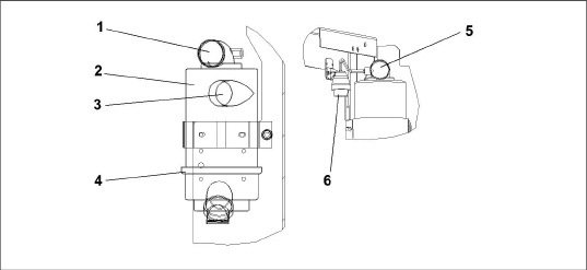
1)Air Outlet
2)Air Cleaner Body
3)Air Inlet
4)Cap Clamp
5)Air Outlet
6)Air Filter Indicator
- - - - -
See Figure 5.3 for this procedure.
The oil cup should be inspected during pretrip, before each trip. Never allow more than 12.7 mm of dirt deposit in the cup. More than 12.7 mm accumulation could result in oil and dirt carrying over into the engine, causing accelerated engine wear. Heavily contaminated oil will not allow the air cleaner to function properly.
Always cover the engine inlet tube while the air cleaner is being serviced.
1.Stop the engine and remove the oil cup from the air cleaner. Dispose of the oil in an environmentally safe manner.
2.Remove the inner oil cup from the oil cup and clean both cups.
3.Reassemble and fill both oil cups to the indicated level with oil specified in Table 2–4.
Do not underfill or overfill the oil bath cups. Overfilling cups causes loss of capacity; underfilling cups causes lack of filtering efficiency.
Figure 5.3 Air Cleaner, Oil Bath
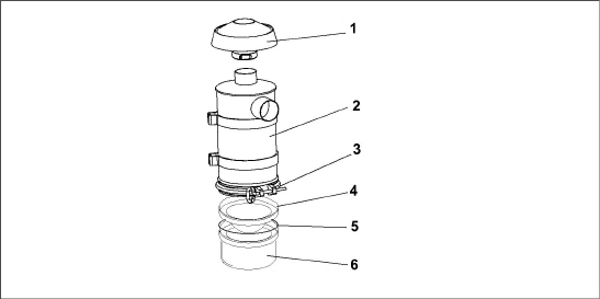
1)Air Inlet Hood
2)Air Cleaner Body
3)Cap Clamp
4)Inner Oil Cup
5)Gasket
6)Oil Cup
- - - - -
The air cleaner body should be inspected each time the oil cup is serviced. If there is any sign of contaminant buildup or plugging, the air cleaner body should be removed and back flushed.
At least once a year, or at regular engine service intervals, remove the entire air cleaner and perform the following cleaning procedure:
1.Remove oil cup. Check and clean center tube.
Do not use gasoline to clean air cleaner parts.
2.Pump solvent through the air outlet with sufficient force and volume to produce a hard, even stream out of the bottom of the body assembly. Reverse flush until all foreign material is removed.
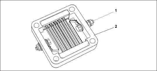
5.4.12Engine Crankcase Breather
The engine uses a closed type breather (see Figure 5.4) with the breather line attached to the cylinder head cover. It is not necessary to disassemble valve style elements for cleaning. However, the bleed hole should be checked for obstructions. Check once a year or at every 4,000 hours maintenance interval, whichever comes first.
Figure 5.4 Engine Crankcase Breather
1)Screw
2)Breather Valve
3)Breather Tube
4)Breather Cover
5)Bleed Hole
- - - - -
1.Disconnect the lead from the heater terminal.
2.Measure the resistance between the heater positive terminal and the heater body.
3.If the resistance is infinity or significantly different than the specification, resistance (cold) 0.3 ohms, replace the heater.
1)Positive Terminal
2)Heater Body
- - - - -
1.Remove the harness connection from the heater.
2.Remove the intake transition mounting hardware.
3.Remove the intake transition, heater and both gaskets.
4.Clean the old gasket material off the transition and manifold mounting services.
5.Install the new heater with a new gasket on either side.
6.Assemble transition to heater and torque mounting hardware (refer to engine manual for torque values).
7.Reconnect the harness to heater connection point.
8.Coat the stud on the heater with protective coating.
5.4.15Intake Heater Switch (HS)
1.Remove the control box cover.
2.Remove all connections going to the Heater Switch (HS).
3.Remove the Heater Switch (HS) from the control box.
4.Install the new Heater Switch (HS).
5.Reconnect the wire harness connections to the switch.
6.Confirm wires are connected to the correct terminals.
7.Reinstall the control box cover.
5.5.1Remove and Replace Procedure
The only serviceable parts on the generator are the torsional dampener, key, fan, and fan cover. If there is a problem with the generator, it should be replaced using the following procedure.
For Unidrive torque requirements, see Section 5.7.
Procedure:
1.Remove the unit top and side panels in order to access the generator.
2.Disconnect the battery.
Observe proper polarity when installing the battery or connecting a battery charger, the negative battery terminal must be grounded. Reverse polarity may damage the charging system. When charging the battery in unit, isolate the battery by disconnecting the negative battery terminal first, then the positive. Once the battery has been charged, connect the positive battery terminal first, then the negative.
3.Remove the truss assembly center nuts and nut plate.
4.Remove the truss side bolts / washers and spacers (2), and remove the truss.
5.Remove the 3/8” bolt / washer that secures the wire harnesses and fuel lines to the top of the generator. Move the wire harnesses and fuel lines out of the way.
6.Remove the 1/4” bolts / washers (4) that secure the battery charger bracket to the unit frame. This will allow you to access the cables on the bottom of the battery charger.
7.Mark and disconnect the cables on the battery charger and remove the battery charger assembly from the unit.
8.Remove the bolts / washers (6) that secure the receptacle box to the unit. Wire-tie the receptacle box to the side of the unit so that the receptacle box is not hanging by the cables.
9.Remove the tape on the wire harness and cut the wires (5) that connect the receptacle box to the generator. Make sure to cut the wires on the receptacle box side of the current butt splices.
10.Remove the bolts / washers (2) that secure the generator support plate to the two generator shockmounts.
11.Remove the bolts / washers (3) that secure the lower radiator access panel (on the other side of the unit) in order to access the engine shockmounts.
12.Back off about 25mm, but do not remove the engine shockmount bolts. This will allow the engine / generator to be slightly lifted off of the unit frame.
The generator / engine must be slightly lifted off of the unit frame in order to provide enough clearance for the generator support plate to slide away from the unit frame.
13.Using the lifting lugs on the top of the generator, lift the generator / engine several inches so that the generator support plate will clear the unit frame allowing the entire generator assembly to be removed.
14.Place several support beams under the engine and then lower the generator / engine onto the beams. Make sure that the generator support plate is lifted high enough to allow for the removal of the generator assembly, but not so high that the fan hits the radiator coil.
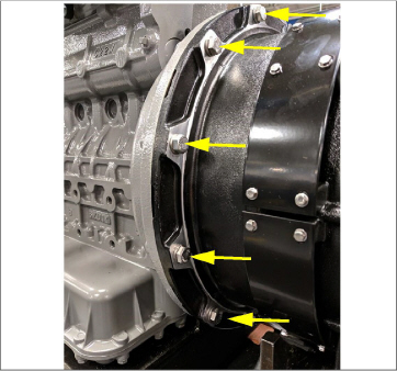
15.Starting with the lower bolts, remove the 3/8”-16 bolts / washers (12) that secure the generator to the engine.
Although the generator torsional dampener and flywheel adapter plate will normally keep the generator coupled to the engine, even without the bolts, it is safest to remove the lower generator bolts first, in case the generator shifts and falls during bolt removal.
16.Lift the generator assembly (generator & support plate) off of the unit frame and lower it onto a stable work surface.
Inspect the generator torsional dampener, bolt, and key as they will have to be removed from the old generator and installed onto the new generator. Replace these components if they are worn or damaged.
17.Remove the generator torsional coupler bolt / washer and pull off the torsional dampener.
18.Place the torsional dampener on the new generator shaft.
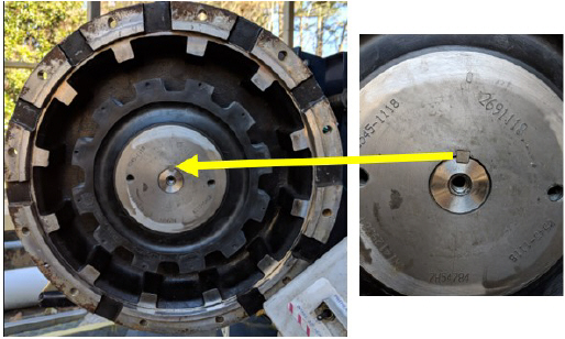
19.Insert the key into the keyway of the generator shaft. See Figure 5.6.
Figure 5.6 Generator Shaft Keyway
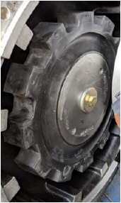
20.Apply Loctite 262 to the generator coupler bolt. Install with washer and torque to 38 N-m (28 ft-lbs). See Figure 5.7.
In order to torque generator torsional dampener gear bolt, use a strap wrench or similar device to secure the dampener while torquing the bolt.
Figure 5.7 Generator Coupler Bolt
21.Remove the generator support plate from the old generator and install it onto the new generator.
22.With the torsional dampener and support plate installed on the new generator, lift and position the generator so that the generator mounting holes (12) are lined up with the engine mounting holes.
23.Insert two generator alignment bolts (2 1/2”) to temporarily align / secure the generator to the engine. Tighten the bolts enough so that the torsional dampener on the generator is touching the aluminum housing on the engine. Do not over tighten the alignment bolts, as they will bottom out on the engine bell housing. See Figure 5.8.
Align the torsional dampener and aluminum housing by rotating either one to seat correctly.
Figure 5.8 Generator Alignment Bolt
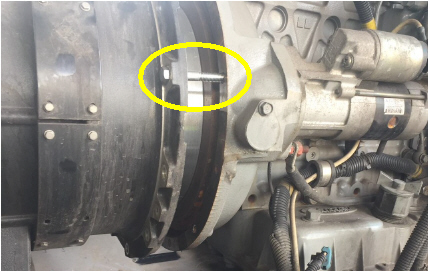
24.Once aligned, push the generator to fully seat the torsional dampener into the aluminum housing of the flywheel adaptor plate.
25.With the torsional dampener seated into the aluminum housing, the alignment bolts (2) can be removed, and the generator mounting bolts (12) can be reinstalled. Torque to 34 Nm (25 ft-lb). Install several mounting bolts to secure the generator before removing the alignment bolts. See Figure 5.9.
Although the torsional dampener and mating surface of the generator will generally keep the generator coupled to the engine, even with all of the bolts removed, it is safest to start installation of the top generator bolts first, just in case the generator shifts.
Figure 5.9 Generator Mounting Bolts
26.With all of the generator mounting bolts secured, use the lift to raise the generator / engine in order to remove the support blocks under the engine.
27.Place the generator support plate mounting bolts (2) down into the generator support plate in order to line up the mounting bolt holes with the shockmounts.
28.Ensure that the large washers placed on the shockmounts and slowly lower the generator / engine so that the generator support plate holes line up with the shockmount holes.
29.Remove the generator support plate bolts and install the bolts / large washers from the bottom of the shockmounts through the generator support plate. Secure the bolts (2) with nuts, torque to 102 Nm (75 ft-lb).
30.Tighten the engine shockmount bolts, torque to 122 Nm (90 ft-lb).
31.Replace the lower radiator access panel and secure with bolts / washers (3).
32.Re-secure the battery charger cables to the bottom of the battery charger.
33.Observe proper polarity when installing the battery or connecting a battery charger, the negative battery terminal must be grounded. Reverse polarity may damage the charging system. When charging the battery in unit, isolate the battery by disconnecting the negative battery terminal first, then the positive. Once the battery has been charged, connect the positive battery terminal first, then the negative.
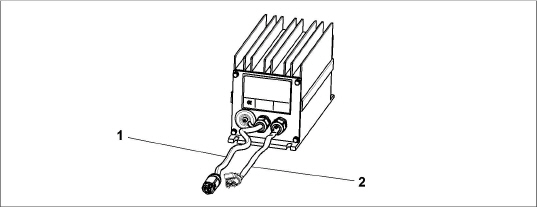
1)AC Wiring from Generator
2)DC
Wiring to 12v Battery
Red (+), Black (-)
- - - - -
34.Re-secure the battery charger assembly to the unit frame.
35.Cut the wire-tie supporting the receptacle box to the unit frame and re-secure the receptacle box to the unit frame using bolts and washers (6). Make sure the receptacle wires are pulled through the access port in the frame and ensure that they will be accessible to splice with the generator wires.
36.Place two pieces of heat shrink tubing (1 large, 1 small) over each receptacle box wire.
37.Connect and butt splice the receptacle box harness wires with the new generator wires.
38.For each of the other five wires, heat shrink the small tubing first, and then the large tubing to ensure a watertight seal.
39.Neatly tape all wires together.
40.Replace and secure the wire harnesses onto the top of the generator, secure with the bolt.
41.Replace the truss and the truss brackets, secure the sides with the mounting bolts (2). See Figure 5.13.
Installing the two back truss bolts first allows the truss assembly to be pulled forward slightly, making it easier to install the two front truss bolts.
42.Secure the center of the truss to the isolator by installing the nuts (2) and nut plate (1).
43.Connect the battery.
44.Re-install the top and side panel covers.
5.6General Generator Set Maintenance
5.6.1Maintenance of Painted Surfaces
The unit is protected against the corrosive atmosphere in which it normally operates by a special paint system. However, if the paint system is damaged, the base metal can corrode. If the paint system is scratched or damaged, do the following:
1.Clean area to bare metal using a wire brush, emery paper or equivalent cleaning method.
2.Immediately following cleaning, spray or brush on a zinc rich primer.
3.After the primer has dried, spray or brush on finish coat of paint to match original unit color.
5.6.2Check and Replace Isolators / Shockmounts
Continued operation with failed shockmounts may result in engine or generator damage. When a shockmount has been cut, split, abraded or has flared due to normal deterioration, it must be replaced. Damage to the mounts may not be visible when installed and under load from the component. To correctly inspect shockmounts, they must be removed.
Engine Isolator / Shockmount Replacement
1.Use the two lift eyes to lift and support the engine.
2.Remove truss, unidrive isolator and all hardware as shown in Figure 5.13.
3.Remove all hardware as shown in Figure 5.12.
4.Raise the engine just enough to remove the shockmounts as shown in Figure 5.12.
5.Install new shockmounts.
6.Lower the engine enough to assemble hardware as shown and torque per Section 5.7.
7.Remove chains from the lift eyes.
Generator Shockmount Replacement
1.Use the two lift eyes to lift and support the engine.
2.Remove shockmount hardware.
3.Raise the generator just enough to remove the shockmounts as shown in Figure 5.11.
4.Install new shockmounts.
5.Lower the engine enough to assemble hardware as shown and torque. See Section 5.7 for torque values.
6.Remove chains from the lift eyes.
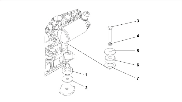
Figure 5.11 Generator Shockmounts
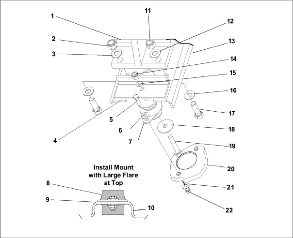
1)Generator
2)Locknut (5/8)
3)Flat Washer (5/8)
4)Support Plate
5)Screw (3/8)
6)Flat Washer (3/8)
7)Shockmount
8)Shockmount
9)Support Plate
10)Frame
11)Locknut (5/8)
12)Flat Washer (5/8)
13)Mounting Base
14)Locknut (1/2)
15)Flat Washer (1/2)
16)Flat Washer (5/8)
17)Screw (5/8)
18)Snubbing Washer
19)Screw (1/2)
20)Frame
21)Flat Washer (3/8)
22)Locknut (3/8)
- - - - -
Figure 5.12 Engine Shockmounts
1)Shockmount
2)Snubbing Washer
3)Bolt
4)Lock Washer
5)Snubbing Washer
6)Shockmount
7)Flat Washer
- - - - -
Figure 5.13 Truss and Isolator
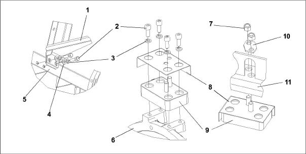
1)Truss
2)Bolt
3)Lock Washer
4)Flat Washer
5)Frame
6)Unidrive
7)Locknut
8)Heat Shield
9)Isolator
10)Nutplate
11)Truss
- - - - -
5.7Unidrive Torque Requirements
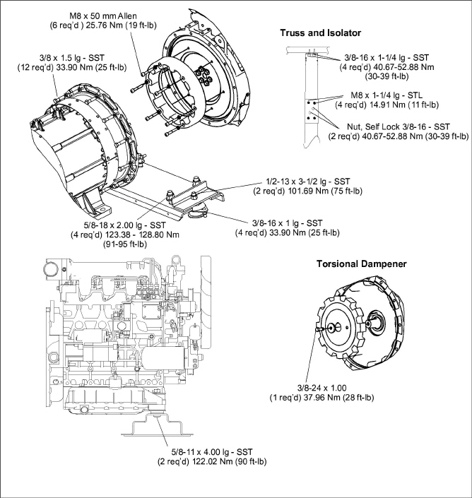
Extensive damage may occur if the proper hardware is not used and/or proper procedures are not followed when working with the unidrive assembly. Periodic inspection of hardware and bolt torque is recommended to ensure the integrity of the unidrive. Torque value and hardware requirements for unidrive assembly are provided in Figure 5.14.
SST is an abbreviation for 300 Series Corrosion Resistant Steel. Loctite #242 or an equivalent product should be used on ALL hardware shown in Figure 5.14.
Figure 5.14 Unidrive Torque Requirements