Section 2
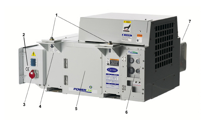
The Carrier Transicold model 69UG15 Series 55 diesel-driven generator set (see Figure 2.1) provides a constant electrical power supply for all-electric refrigeration units. The 69UG15 is an under-mounted unit secured to the frame rails of the container trailer chassis.
The generator set consists of a diesel engine directly connected to an alternating current generator and mounted in a structural steel frame. The engine is a vertical, in-line, four cylinder diesel manufactured by Kubota. The generator is a 15 kW, permanent, single winding, dual bearing type that supplies nominal 50/60Hz power.
Electrical controls are mounted in a control box with operating controls and gauges mounted on a control panel, which also serves as the control box cover. The control panel components are protected by a deflector assembly and a windowed control box door.
The Series 55 model bears the CE mark (Figure 2.1), verification that its 18.5 kW engine complies with Europe’s Stage V non-road mobile machinery emissions standard, which includes low thresholds for carbon monoxide, hydrocarbons, particulate matter and nitrogen oxides.
- - - - -
2.2Configuration Identification
Generator set identification information is provided on a unit nameplate located next to the access service door (front facing). The label provides the generator set model number, serial number, and parts identification number (PID). The model number identifies the overall configuration while the PID provides information on specific optional equipment and differences in detailed parts.
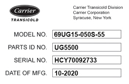
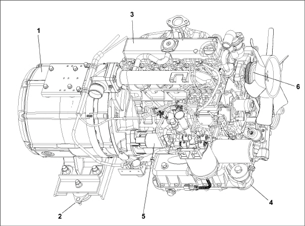
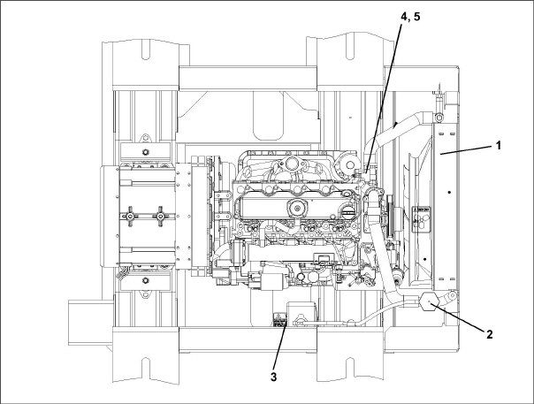
Figure 2.2 Generator Set Components
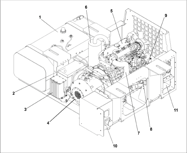
1)Fuel Tank
2)Battery
3)Battery Charger
4)AC Generator
5)Engine
6)Exhaust Muffler
7)Engine Air Cleaner
8)Fuel Filter / Water Separator
9)Oil Filter
10)Receptacle Box
11)Control Panel and Control Box
- - - - -
Figure 2.3 Generator Set Components - Top View
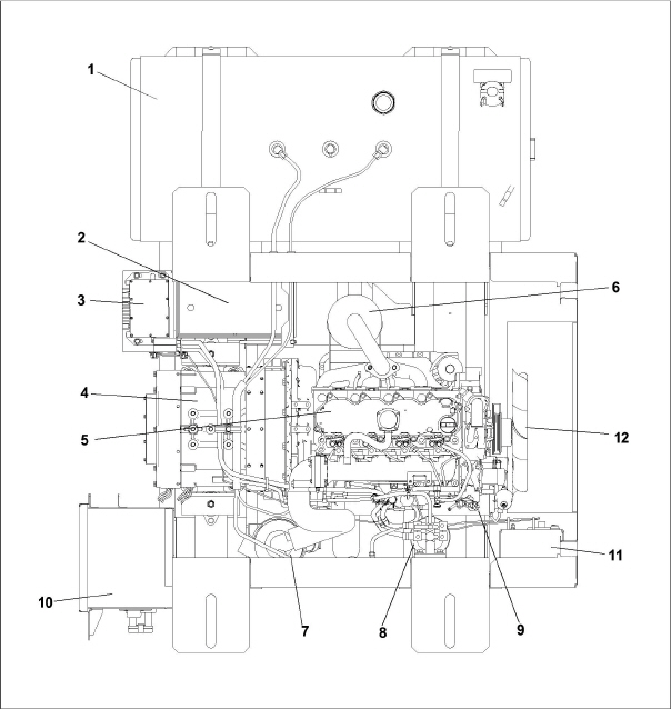
1)Fuel Tank
2)Battery
3)Battery Charger
4)AC Generator
5)Engine
6)Exhaust Muffler
7)Air Cleaner
8)Fuel Filter / Water Separator
9)Oil Filter
10)Receptacle Box
11)Control Panel and Control Box
12)Radiator
- - - - -
2.3Alternating Current Generator
The Alternating Current (AC) Generator (see Figure 2.4) bolts directly to the engine and supplies nominal 50/60Hz power depending on the load requirement.
Generator sets will start at 50Hz. Once the unit is running, the voltage controller will read the voltage output of the generator and adjust accordingly to keep the voltage within ISO limits. As the Container becomes loaded, voltage drops and current increases, causing the generator set to adjust speed based on power demand and ambient conditions. The unit will typically run at 50Hz and vary generator output via winding selection. The speed change to 60 Hz will typically occur when the ambient temperature is high and the unit is heavily loaded.
The Voltage Controller (VC) maintains ISO voltage via two-speed and single winding control. It is used to regulate voltage in order to keep the generator output within ISO limits (see Table 2–3). The Voltage Controller and Voltage Controller fuses (VCF1 and VCF2) are located in the receptacle box (see Figure 2.12).
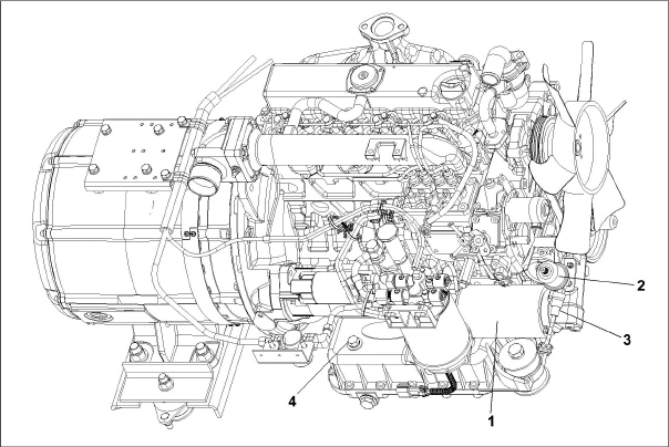
The engine (see Figure 2.4) is a vertical, in-line four cylinder diesel engine, model V2203-DI, that is directly connected to the AC generator. The diesel engine takes air, compresses it and then injects fuel into the compressed air. The heat of the compressed air ignites the fuel spontaneously.
Separately bound manuals covering the diesel engine are available:
•62-10865, V2203-DI Engine Workshop
•62-11695, V2203-DI Parts List
Figure 2.4 Generator and Engine - Unidrive Assembly
1)Generator
2)Generator Shockmount
3)Engine
4)Engine Shockmount
5)Starter
6)Poly V-Belt
- - - - -
The engine fuel system (see Figure 2.5) is a closed circuit that injects a precise amount of atomized fuel into the engine cylinders.
A mechanical lift pump initially transfers fuel at low pressure from the fuel tank and through the fuel shutoff valve. Fuel exits the lift pump and is pushed into the fuel filter / water separator to remove water and finer particles. An optional in-line fuel strainer can be used prior to the fuel filter / water separator to trap large particles. The fuel filter / water separator also contains a 12-volt fuel heater to heat the fuel. Low pressure fuel then enters the injection pump, where it is compressed to higher pressures and distributed to individual fuel lines that supply an injector nozzle for each cylinder. The injector nozzles spray atomized fuel into the combustion chamber based on the timing of the injector pump. Any excess fuel in the nozzles not used for combustion is sent back to the fuel tank.
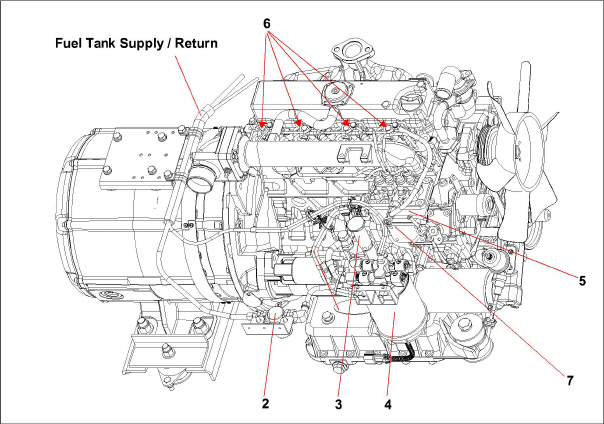
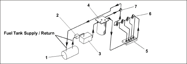
1)Fuel Tank
2)In-Line Fuel Strainer (option)
3)Mechanical Lift Pump
4)Fuel Filter / Water Separator
5)Injection Pump
6)Injector Nozzles (4)
7)Manual Fuel Bleed Valve
- - - - -
The engine requires all air to be removed the system in order to run at optimal performance. The fuel system contains a fuel pump primer on the mechanical lift pump and an air bleed screw after the injection pump, if bleeding air from the system is required.
The engine fuel tank (see Figure 2.6) is available in 50 and 65 gallon capacity, with 50 gallon standard.
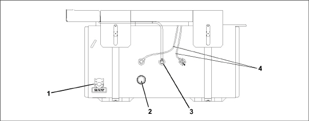
1)Cap
2)Gauge
3)Vent
4)Fuel Lines
- - - - -
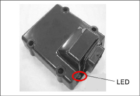
The electronic governor controls the speed of the engine by using an Electronic Governor Module (EG), Fuel Solenoid (FS) and an Engine Speed Sensor (ESS).
The EG (see Figure 2.7) is a solid state control module pre-programmed for 1800 RPM high speed and 1500 RPM low speed operation. The EG receives an input signal from the ESS of the current RPM and compares this to a preset value. The EG sends a correction signal to the FS to maintain the proper RPMs.
The EG is mounted in the control box and has an LED which may assist in diagnosing failures within the electronic speed control system. See Section 4.4 for additional troubleshooting information.
Figure 2.7 Electronic Governor Module (EG)
2.4.3Engine Lubrication System
The engine lubrication system (see Figure 2.8) keeps the engine running smoothly, providing a supply of lubricating oil to the various moving parts in the engine. The main function is to enable the formation of a film of oil between moving parts, to reduce friction and wear.
The engine lubricating oil filter is mounted in a horizontal arrangement. The Oil Pressure Sender (OPS), located at the oil filter housing, senses lube oil pressure and transmits a signal to the Oil Pressure Gauge located on the control panel (see Figure 2.11). The Low Oil Pressure (LOP) switch opens when engine lubricating oil pressure is observed below 1.27 kg/cm.
Figure 2.8 Engine Lubrication System
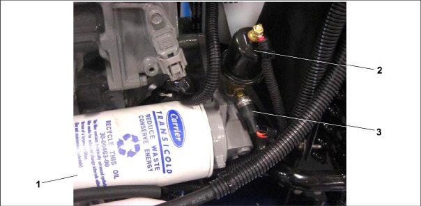
3)Low Oil Pressure (LOP) Switch
4)Oil Dipstick / Fill Cap
- - - - -
2.4.4Engine Air Cleaner System
The engine air cleaner system (see Figure 2.9) utilizes a filter element to filter the engine intake air. The air cleaner is designed to effectively remove contaminants from the air stream, resulting in prolonged engine life and reduced wear on all engine operating parts. When a dry element air filter is utilized, an air filter indicator is mounted on the air filter body to indicate when the filter element needs to be replaced.
Air exits the air cleaner and then enters the air intake heater (IH), which heats the air before it enters the engine cylinder. This is done to help engine starting in cold temperatures.
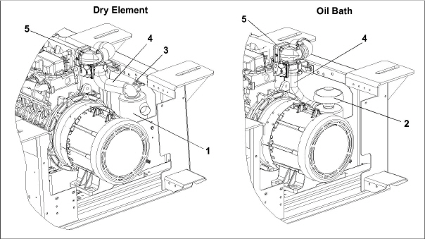
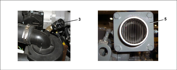
1)Air Cleaner, Dry Element
2)Air Cleaner, Oil Bath
3)Air Filter Indicator
4)Air Inlet Hose
5)Air Intake Heater (IH)
- - - - -
The engine cooling system (see Figure 2.10) uses extended life coolant and a radiator to keep the engine from overheating. The radiator transfers the heat from the engine coolant to the surrounding air. The water pump and the radiator cooling fan are belt-driven from the engine crankshaft. The High Water Temperature Switch (HWT) and Water Temperature Sender (WTS) monitor and regulate cooling water temperature.
Figure 2.10 Engine Cooling System
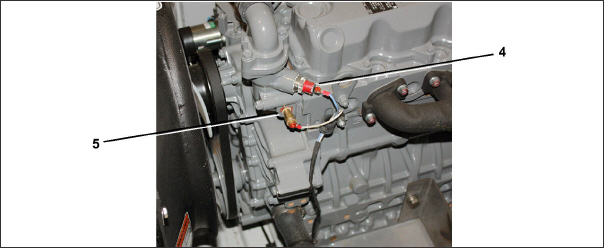
1)Radiator Assembly
2)Radiator Fill Cap
3)Coolant Recovery Bottle
4)High Water Temperature Switch (HWT)
5)Water Temperature Sender (WTS)
- - - - -
2.5Battery and Battery Charging System
The battery provides 12 VDC power to the starter motor. It also provides the initial voltage for the Intake Heater until the unit starts.
The solid state battery charger is located in front of the battery. The battery charger is powered by the generator, and this input is protected by fuses located in the receptacle box. The battery charger produces a tapered charge (40 amps maximum) and is designed not to overcharge the battery.
Observe proper polarity when installing the battery or connecting a battery charger. The negative battery terminal must be grounded. Reverse polarity may damage the charging system. When charging the battery in unit, isolate the battery by disconnecting the negative battery terminal first, then the positive. Once the battery has been charged, connect the positive battery terminal first, then the negative.
2.6Control Panel and Control Box Components
The control panel and control box (see Figure 2.11) contain components required for monitoring and controlling the Genset unit.
The Water Temperature Gauge observes water operating temperature. Once the unit has achieved normal running temperature, the coolant temperature is between 82 - 96°C. The Water Temperature Sensor senses engine water temperature and transmits a signal to the Water Temperature Gauge.
The Oil Pressure Gauge observes normal operating engine oil pressure. Normal oil pressure is 3.3 to 5.2 kg/cm2. The Oil Pressure Sender (see Figure 2.8), located at the oil filter housing, senses lube oil pressure and transmits a signal to the Oil Pressure Gauge.
The Total Time Meter (TT) calculates the total hours the unit has been running, which provides an accurate readout of accumulated engine running time. This data can be used to establish proper maintenance schedules (refer to Table 5–1).
The Ammeter indicates the rate of charge or discharge of the battery charging system. The battery charging system is composed of the battery and the battery charger, either solid state or alternator. During start up, the intake heater draws approximately 42 amps.
2.6.5Intake Heater Switch (HS)
The Intake Heater Switch (HS) is a momentary switch. When held in the PREHEAT position, the switch allows approximately 42 amps of battery current to flow into the intake heater, which preheats the air within the intake manifold and allows the engine to start. After starting the engine, the intake heater switch should continue to be held in the ON position for approximately 5 seconds until the engine has developed enough oil pressure to close the oil pressure safety switch.
The Ignition Switch (IGN) is a momentary switch that has OFF/ON/START positions. When held in the START (ignition) position, it energizes the starter motor solenoid, which in turn allows the starter motor to crank the engine. The switch is released to the RUN position once the engine has started.
2.6.7Intake Heater Timer (IHT)
The Intake Heater Timer (IHT) continues to supply power to the intake heater for 3 minutes after initial start-up.
2.6.8Starter Solenoid Timer (SST)
The Starter Solenoid Timer (SST) limits the amount of time that the starter can be engaged to 15 seconds. If the starter is manually engaged for more than 15 seconds, power will be cut to the starter. Once power has been removed, the starter can again be engaged for up to 15 seconds.
Figure 2.11 Control Panel and Control Box
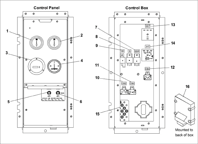
1)Water Temperature Gauge
2)Oil Pressure Gauge
3)Total Time Meter (TT)
4)Ammeter (A)
5)Intake Heater Switch (HS)
6)Ignition Switch (IGN)
7)Starter Solenoid Relay (SSR)
8)Safety Relay (S)
9)Intake Heater Relay (HR)
10)Circuit Breaker (CB2)
11)Circuit Breaker (CB3)
12)Circuit Breaker (CB4)
13)Starter Solenoid Timer (SST)
14)Intake Heater Timer (IHT)
15)Ground Studs
16)Electronic Governor Module (EG)
- - - - -
The Receptacle box (see Figure 2.12) contain components required for monitoring and controlling the Genset unit.
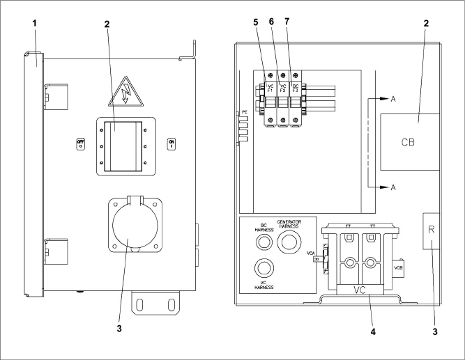
1)Access Cover
2)Circuit Breaker (CB1) Genset
3)Receptacle
4)Voltage Controller (VC)
5)Voltage Controller Fuse (VCF1)
6)Voltage Controller Fuse (VCF2)
7)Battery Charger Fuse BCF3
- - - - -
Safety devices, such as circuit breakers, fuses, and safety switches protect system components from damage.
The AC generator, solid state battery charger, fuel heater, high water temperature, safety relay, total time meter and intake heater are protected by circuit breakers. If a safety device opens and there is an interruption of electrical current, the electronic governor module will be de-energized, which will also de-energize the fuel solenoid, interrupt the fuel flow to the engine and stop the engine.
Safety device specifications are provided in Table 2–1.
Output: |
15 KW, 18.75 KVA, 0.8 pf KW |
|---|---|
Output Voltage: |
400-500 VAC @ 60 hz 360-460 VAC @ 50 hz |
Speed: |
1800 RPM @ 60 hz 1500 RPM @ 50 hz |
Weight: |
121 kg |
Part Number: |
54-00738-20 |