


Section 3
3.1 GENERATOR SET INSTALLATION
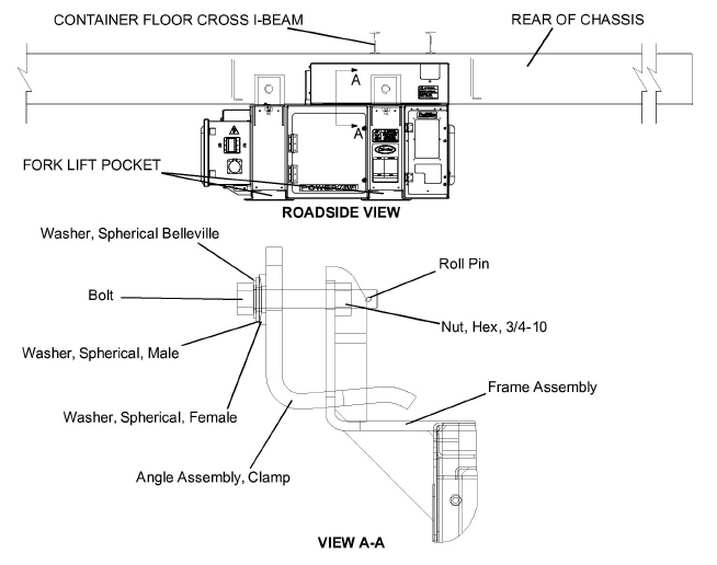
The generator set is mounted under the center of the trailer chassis and is easily handled with a fork lift truck capable of handling 2,000 pounds. The fork lift pockets provided are accessible from either side. Mounting clamps are designed to be attached to outside I-beam flanges only. Maximum chassis width is 38 inches on center.
1. Standard Mount
a. Loosen mounting bolts (see Figure 3.1) sufficient to push mounting plates to the outermost position.
b. Place forks into fork lift pockets of generator set. Attach safety chain between unit and fork truck.
c. Center generator under chassis slide mounting plates fully onto chassis I-beams and torque mounting bolts to 80 - 90 ft-lbs (11.1 - 12.4 m-kg). Upon completion, remove safety chain before removing forks of fork lift truck from unit.
2. Quick Mount
a. Loosen mounting bolts (see Figure 3.2) sufficient to bring clamp to open position. To orient in open position, lift nut end of bolt out of slot. Clamp will fall open.
b. Place forks into fork lift pockets of generator. Attach safety chain between unit and fork truck.
c. Center the generator set in desired position under chassis.
d. Lift clamp in place, ensuring bolt is secured in slot.
e. Tighten bolt to 55 - 65 ft-lbs (7.6 - 9.0 m-kg).
f. Upon completion, remove safety chain before removing forks of fork lift truck from unit.
Figure 3.1 Generator Set Mounting - Standard Mount
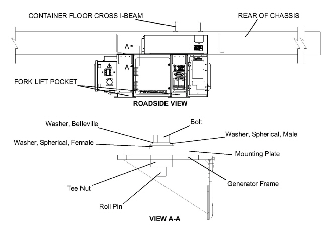
Figure 3.2 Generator Set Mounting - Quick Mount
1. Standard Mount
a. Disconnect power cable to generator (if connected).
b. With fork lift in position and safety chain attached, slide mounting plates back sufficiently to clear chassis.
c. Lower and remove generator.
2. Quick Mount
a. Disconnect power cable to unit (if connected).
b. With fork lift in position and safety chain attached, loosen mounting bolts, and lift end of bolts out of slot to orient clamps to open position.
c. Lower and remove generator.
3.3 STARTING AND STOPPING INSTRUCTIONS
1. Check engine lubrication and fuel filters, oil lines, and connections for leaks. If required, tighten connections and/or replace gaskets.
2. Check engine lubricating oil level. (Refer to Section 2.10, table entry f.)
3. Check poly V-belt for fraying or cracks and proper tension. (Refer to Section 5.4.11).
4. Check radiator hoses for leaks and check radiator coolant level. (Refer to Section 2.10, table entry j.)
5. Check radiator coil and generator air intake screen for cleanliness. If required, clean using compressed air, reversing the normal air flow.
6. Check air cleaner for cleanliness and clean if necessary. (Refer to Section 5.4.12.)
7. Check in−line fuel strainer and clean if necessary. (Refer to Section 5.4.4.)
8. Drain water from fuel tank sump and filter bowl.
9. Fill fuel tank with diesel fuel. (Refer to Section 2.10, table entry g.)
10. Check air intake heater amperage. (Refer to Section 2.10, table entry h.)
11. Check battery terminals for cleanliness and secureness. If required, clean, then coat with a battery terminal sealant.
12. Check, and if required, tighten all electrical connections.
13. Check, and if required, tighten all hardware (brackets, etc.).
14. Ensure the main generator set circuit breaker (CB1) is in the OFF position. Connect power cable to refrigeration unit and proceed to Section 3.3.2.
Before start up, both the Genset circuit breaker (CB1) and the refrigerated unit should be OFF. After start up, the Genset unit should be run for at least two minutes to allow the power source to stabilize before supplying power to the refrigerated unit. This will eliminate the potential of any cold start transient spikes from reaching the refrigerated unit. Cold start transient spikes can potentially cause nuisance over voltage alarms on refrigerated units that are sensitive to electrical spikes or transients.
Beware of moving poly V-belt, belt driven components and hot exhaust components.
Under no circumstances should ether or any other unauthorized starting aids be used in conjunction with the air intake heater.
Piston rings in engines that have operated less than 100 hours may not be fully seated. This may lead to the possibility of oil seepage from the exhaust pipe. To properly seat the rings, operate the engine under full load for a period of 24 hours. If the condition persists, check valve clearance when the engine is cold. (Refer to engine workshop manual listed in Section 2.2).
1. Standard Units
a. Make sure that CB-1 is in the OFF position.
b. Hook up the 460 volt cable from the refrigerated unit to the Genset receptacle.
c. Hold intake heater switch (see Figure 2.7) in the PREHEAT position. Suggested hold times for a cold engine are as follows:
|
COLD ENGINE PREHEAT TIMES |
|
|---|---|
|
Ambient Temperature |
Time |
|
78°F/26°C |
5 seconds |
|
32°F to 78°F (0° to 26°C) |
10 seconds |
|
18°F to 32°F (-8° to 26°C) |
20 seconds |
|
Below 18°F/-8°C |
30 seconds |
d. With the intake heater switch held in the PREHEAT position, place the ignition switch in the START position.
e. After the engine has started, continue to hold the intake heater switch in the PREHEAT position until the engine develops sufficient oil pressure to close the oil pressure safety switch (approximately 5 seconds). When released, the intake heater switch will automatically return to the OFF position and the heater will remain energized for 3 minutes.
2. Units with Auto Start
a. Make sure that CB-1 is in the OFF position.
b. Hook up the 460 volt cable from the refrigerated unit to the Genset receptacle.
c. Place the Ignition switch (IGN) in the RUN position.
d. If the low coolant sensor (LCS) is immersed in coolant, the auto restart module will energize the heater for 30 seconds and the safety buzzer will sound. After the 30 second delay, the unit will attempt to start.
1. Allow the Genset unit to run for at least 2 minutes.
2. Turn on CB-1.
3. Check generator output with a volt meter, voltage output at start up with no load at 50Hz operation should be:
Voltage output may vary and fall with ISO specifications based on ambient (Refer to Section 2.6)
4. Start refrigeration unit.
5. Run engine 10 minutes (check total time meter operation).
6. Listen for abnormal bearing noise (AC generator).
7. Check fuel lines, lube oil lines, and filters for leaks.
8. Check exhaust system for leaks.
1. Place CB-1 in the OFF position.
2. Place the ignition switch in the OFF position.
3.4 SEQUENCE OF OPERATION WARNING
Beware of moving poly V-Belt and belt driven components.
1. Standard Units:
With the intake heater switch (HS) held in the ON position, current flows through the ammeter to the intake heater. While the heater is on, the ammeter will show a 42−amp draw.
A second set of contacts also energizes the safety relay (S).
If the high water temperature switch (HWT) opens to break the safety relay ground connection, the safety relay will not energize, and the engine will not start.
To start the engine, the ignition switch (IGN) is held in the START position. With the switch in the START position, current flows to the start solenoid (SS), through the SS contacts to the starter motor (SM). Current then flows to the intake heater timer, intake heater relay (HR) and to the heater, while simultaneously powering the electronic governor module (EG), fuel solenoid (FS), and engine speed sensor (ESS).
The starter motor turns over the engine resulting in pumping of fuel to the engine cylinders by the injection pump. This fuel is ignited by heat of compression; thus starting the engine. When the engine has developed sufficient oil pressure, the low oil pressure switch (LOP) contacts close to maintain power to the safety relay (S).
Once the engine has started, the intake heater (IH) will remain energized for 3 minutes.
The ignition switch (IGN) will be released. The intake heater switch (HS) will be held for 5 seconds, then released after the ignition switch is released. When the START switch is released, the starter will be disengaged.
With the engine running, the battery charger provides DC power to operate the control system and charge the battery.
2. Units with Auto Start, Low Coolant Sensor:
When the ignition switch (IGN) is placed in the RUN position, 12-volt DC power is applied to the low coolant sensor (LCS), if applicable, and the auto restart module simultaneously. If the coolant level is below the sensor, all the indicator lights on the auto restart module will blink once and the LCS will open the contacts on the low coolant relay, de-energizing the unit’s 12-volt DC circuitry. If the coolant level is above the sensor, the auto restart module will maintain power and all lights on the module will illuminate. As the auto restart module performs its self test, the lights will go out individually.
After the self test is complete, the auto restart module will energize the intake heater and sound the audible alarm warning, indicating that the unit has been powered on and will start. The 30−second delay starts at this time. When the 30−second delay expires, power will be applied to the electronic governor and the engine attempts to crank for 15 seconds.
When the engine starts, the intake heater will remain energized for 3 minutes; during this time, the engine/intake heater light and alarm will be energized, the shutdown/lockout time delay of 15 seconds will begin counting, and the starter will be disengaged. During the shutdown/lockout time delay at start up, the auto restart module will disregard the signals to the oil pressure and engine temperature inputs, and the Run sequence will begin. If engine does not start, refer to Table 2–2 for auto restart sequencing.