Introduction
This manual contains information specific to the Carrier Transicold EverFRESH® Controlled Atmosphere option. This manual is to be used in conjunction with the separately bound Operation & Service Manual and Service Parts Manual for the model of your particular refrigeration unit.
The EverFRESH system is able to control container atmosphere by supplying nitrogen and oxygen into the contained space and simultaneously controlling levels of O2 and CO2. This extends the produce ripening process, which increases shelf life and enables longer cargo routes for certain perishable commodities. The EverFRESH system also offers an optional package to actively inject CO2 into the cargo space during transport.
2.2Controlled Atmosphere Unit - Component Descriptions
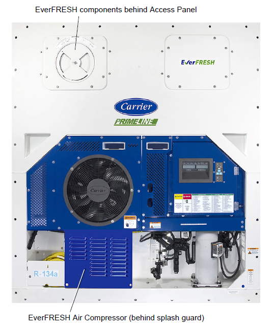
The refrigeration unit is designed for the majority of its components to be accessible from the front, see Figure 2.1. The air compressor for EverFRESH is located below the condenser behind a splash guard. A manually operated venting system is located in the upper left access panel. The panel may be removed to allow entry into the evaporator section where the atmosphere sensors, control valves, water separator and air filters are located.
Figure 2.1 Refrigeration Unit - Front
Other than the air compressor, the EverFRESH option components are mounted in the evaporator section (Figure 2.2) in addition to the standard refrigeration unit components.
These components, as shown in Figure 2.3, include the water separator, particulate filters, water drain valve (WDV), nitrogen membrane separator, EverFRESH air valve (EA), EverFRESH nitrogen valve (EN), CO2 and O2 sensor package, and membrane pressure transducer (MPT).
Air from within the container is passed to the O2 sensor and CO2 sensor. Data is then supplied to the controller. The controller calculates O2 and CO2 values in order to maintain the preset values.
Figure 2.2 Refrigeration Unit - Evaporator Section (Upper Panel Removed)
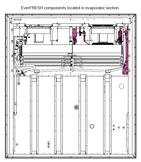
Figure 2.3 EverFRESH Components
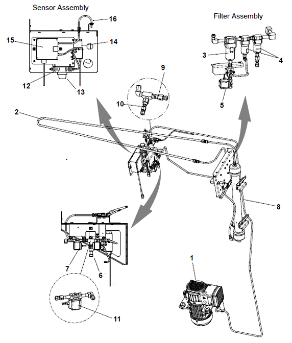
1)Air Compressor
2)Condensing Loop
3)Water Separator
4)Particulate Filters (2)
5)Water Drain Valve (WDV)
6)Membrane Pressure Transducer (MPT)
7)EverFRESH Air Valve (EA)
8)Nitrogen Membrane Separator
9)Nitrogen Supply Orifice
10)Nitrogen Sampling Orifice
11)EverFRESH Nitrogen Valve (EN)
12)Cargo Air Sensor Inlet
13)Cargo Air Sensor Filter Assembly
14)O2 Sensor
15)CO2 Sensor
16)Cargo Air Sensor Outlet
- - - - -
2.3Optional CO2 Injection System
There is an optional CO2 injection kit, as shown in Figure 2.4, that can be added to the system to actively inject CO2 into the cargo space during transport. In this configuration, a CO bottle with a regulator maintains an input pressure of 50 psig, not to exceed 100 psig. There are two CO2 injection ports: one internal and one external. The connection is a 1/4” flare fitting with a Schrader valve.
The service kit for field installation of the CO2 injection system is part number 74-00322-00.
Figure 2.4 CO2 Injection System
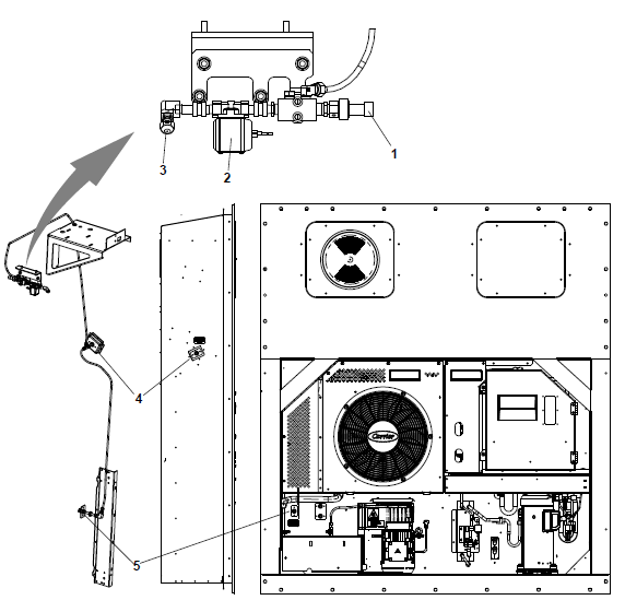
1)CO2 Injection Pressure Transducer (IPT)
2)CO2 Injection Solenoid Valve (CSV)
3)CO2 Supply Orifice Cap
4)Internal CO2 Port
- - - - -
|
Component |
Data |
Detail |
|
Number of Cylinders |
2 |
|
|
Type |
Three Phase Induction |
|
|
Weight |
44 lbs |
|
|
Full Load Amps |
1.34 amps at 50 Hz 1.4 amps at 60 Hz |
|
|
Voltage and Frequency |
360 - 460 VAC at 50 Hz +/-2.5Hz 400 - 500 VAC at 60Hz +/-2.5 Hz |
|
|
Speed |
1425 RPM at 50 Hz 1725 RPM at 60 Hz |
|
|
Horsepower |
0.75 |
|
|
Protection |
Internal thermal protector |
|
|
Number of Cylinders |
2 |
|
|
Type |
Three Phase Induction |
|
|
Weight |
47 lbs |
|
|
Full Load Amps |
1.82 amps at 50 Hz 1.9 amps at 60 Hz |
|
|
Voltage and Frequency |
360 - 460 VAC at 50 Hz +/-2.5Hz 400 - 500 VAC at 60 Hz +/-2.5 Hz |
|
|
Speed |
1467 RPM at 50 Hz 1771 RPM at 60 Hz |
|
|
Horsepower |
1.1 at 60Hz |
|
|
Protection |
Internal thermal protector |
|
|
Voltage and Frequency |
18 to 30 VDC 50/60HZ +/-2.5Hz |
|
|
Amperage |
nominal 250mA @ 24 VAC |
|
|
Type |
AC / DC coil |
2.5Safety System and Protective Devices
Table 2–2 Safety and Protective Devices
|
Device |
Device Setting |
|---|---|
|
Compressor IP |
Thermal |
|
Compressor Pressure Relief Valve |
147 psig +/- 3% |
|
Control Fuses - Auto Blade Type SAE J1284 |
7.5 Amp |
|
Motor Fuses - Ferraz Shawmut ATMR5 |
5 Amp |