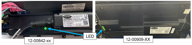
Carrier’s telematics solutions allow users to monitor their units remotely using telematics software. Under normal operation, the device LED will illuminate blue or green, depending on whether the unit is running on power or battery and whether it has Long Range (LoRa) or Cellular communication coverage. When diagnosing the connection to a unit, it is important to determine if the issue is hardware or software related. You can observe what the module is doing based on the LED color and state as described in the tables below. See the next page for more information on no LEDs or LEDs blinking for extended periods of time.
When the Reefer is ON:
|
# |
Color |
State |
Meaning |
|---|---|---|---|
|
1 |
White |
Blinking |
Searching for Reefer Controller Communication |
|
2 |
White |
Solid |
Reefer Communication Found. Lit for 10 seconds |
|
3 |
Red |
Solid |
Reefer Communication Failed (Check Harness Connections) |
|
4 |
Green |
Blinking |
Searching for Cell Coverage |
|
5 |
Green |
Solid |
Device has Cell Coverage |
|
6 |
Blue |
Blinking |
Searching for LoRa Coverage |
|
7 |
Blue |
Solid |
Device has LoRa Coverage |
When the Reefer is OFF:
|
# |
Color |
State |
Meaning |
|---|---|---|---|
|
1 |
Blue |
Very Short Blinking |
Device is active (it will report a message periodically) |
|
2 |
None |
None |
Device out of battery, turn reefer on for >1 hour to charge |
Green or blue blinking LEDs for more than 5 minutes:
If the LED is blinking green or blue for extended periods of time, it may be due to poor coverage in the area. If a unit is being diagnosed, ensure the telematics module is not obstructed by any large walls or move the container to an area that is more open. Check to ensure the area has cell coverage by referring to a personal cell phone. If the area is open and has good cell coverage, test a new telematics module by following step 5 in the instructions below.
No LEDs for more than 2 minutes or solid red LED:
If there is no LED for more than 2 minutes, then the communication between the ML3/ML5 controller and telematics device is unsuccessful. This could be due to an incomplete cable connection or a defective telematics device. Follow the steps below:
Follow your company’s standard Lockout/Tagout procedure for working with electrical components.
1.Confirm with the Container Owner: container ID, model number, and telematics device part number.
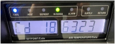
2.Confirm the software version of the controller with Cd 18. The controller software version is equal to or higher than 6322 for ML5 PrimeLINE, 5373 for ML3 PrimeLINE, 5167 for ThinLINE, and 5708 for NaturaLINE. If not, upload the latest revision of the software. NOTE: Check with the container owner before uploading any software.
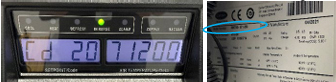
3.Confirm the model number of the unit with Cd 20. It should match the model number listed on the unit’s nameplate. If it does not match, contact the owner of the container to verify the model number. It is recommended that the new model number be documented on the nameplate for future reference.
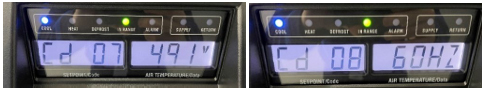
4.Check power supply to the controller with Cd 07 and Cd 08. It should be 400-500 VAC at 57.5-62.5 Hz or 360-460VAC at 47.5-52.5 Hz.
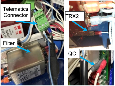
5.Turn off the unit and circuit breaker. Check power connections to the telematics device:
a.TRX2 on the controller transformer, behind the filter in the control box.
b.QC on the ML5 controller and QC1 on the ML3 controller.
c.If there is a telematics connector, check its connections as well.
•Verify connections are seated and not loose.
•If the connections are loose, seat them properly and turn the unit back on and see if the telematic device’s LEDs light up.
•If the connections are fully seated, disconnect the telematics connector, and turn the unit on. Verify there is 20-24VAC across the connection. If voltage is ok, turn off the unit and continue to step 5.
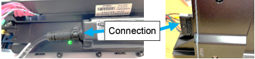
6.Check that the telematics module harness is fully seated in the device. This will either be a screwed-in plug in the center of the module or plugged into the left-hand side of the module. If the connections are fully seated, keep the unit off and continue to step 6.
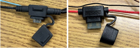
7.Locate the fuse holder along the length of the connection of the telematics unit. Remove the cover and ensure the fuse is not open with an ohmmeter. If the fuse is ok, proceed to step 7, else replace the fuse.
8.Check the other connections of the telematics device to the controller.
a.For ML3 units, check the connections at MA and the MA passthrough.
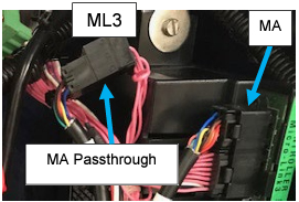
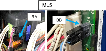
b.For ML5 units, check the connections at RA and BB.
If the connections are loose, seat them properly and turn the unit back on and see if the telematic device’s LEDs light up. If the connections are fully seated, keep the unit off and continue to step 8.
9.Swap the LYNXFLEET device for a new one with the same part number and check the LED pattern for connectivity. If the device’s LED turns solid white, then the original LYNXFLEET device is defective. If the new device does not illuminate the LED, reverify the connection.
10.If the new device does not illuminate the LED upon connection or is still not appearing on the customer interface after a reasonable amount of time, reconnect the original LYNXFLEET device and contact the container owner or telematics service provider for further troubleshooting.
NOTE: The non-provisioned telematics power connector (CIB wire kit) is part number 22-01713-35
** Contact your assigned Carrier Field Service Manager prior to any replacement.
* For clarity it is recommended that this document be printed in color.