Carrier has introduced the ML5 OptimaLINE™ unit (69NT40-701-XXX). This unit builds on the PrimeLINE® platform by adding variable speed compressor, a two-speed condenser fan, and an electronic economizer control circuit.
The OptimaLINE (OL) unit uses the same ML5 controller (12-55016) as the PrimeLINE (PL) units with separate software to operate (6393+). A ML5 controller with PL software can be converted to OL software by using the scrl6393.zip available on the Carrier website.
Warning: A controller with OptimaLINE software cannot be converted to PrimeLINE software. Attempting to load PL software onto a controller running OL software will corrupt the controller and require the controller to be replaced.
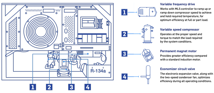
The OL uses the variable frequency drive (VFD, Part number 10-00560-01) to control the speed of the compressor for capacity control using a permanent magnet motor for optimal efficiency. The controller communicates with the VFD via the RB connector on the controller to set the speed. The speed (capacity %) can be viewed with code select Cd01. The VFD (10-00560-01) can be used with both the OL and NaturaLINE® unit (NL). The VFD from NL units PID <NT5103 (10-00482-00) is only to be used with NL units.
Note: All 10-00560-01 VFDs are preprogrammed to operate with NaturaLINE units. When connected to an OptimaLINE unit, the VFD is reconfigured for the OL unit (i.e. in an urgent situation, with no spare VFDs, a 1000560-01 VFD can be removed from a NL unit and installed on an OL unit). Once configured for OL, the VFD cannot be reconfigured to NL.
Unlike the NL unit, the OL unit does not have the “Limp Home” mode capability in case of a VFD failure as the permanent magnet in the compressor cannot be operated directly off 3-phase line current. On a VFD failure, the part needs to be replaced.
OL units use a two-speed condenser motor. This is the same motor used on the 571-3XX PLE units. The speed of the motor is controlled by the CF and CS contactors operated by the controller and will cycle between high and low speed to meet required cooling capacity. The state of the condenser fan speed can be viewed from Cd82.
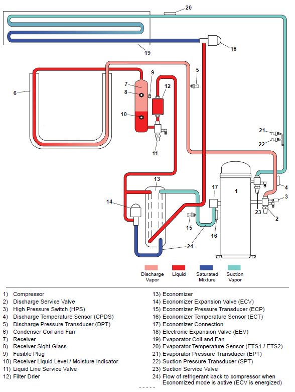
The OL unit uses an electronic economizer expansion valve (ECV) compared to the PL economizer solenoid valve (ESV) and thermostatic expansion valve (TXV) for control on the economizer circuit. The economizer circuit is used to direct the liquid refrigerant flows through the ECV and into the economizer internal passages, absorbing heat from the liquid refrigerant flowing to the electronic expansion valve (EEV). The resultant “medium” temperature / pressure gas is directed back to the compressor. This increases the capacity of the unit. The electronic expansion valve is actuated by the controller based on the readings of the economizer pressure transducer (ECP) and economizer temperature sensor (ECT). This allows for control of discharge superheat control and optimize system efficiency. The ECV position (%) can be viewed from Cd86.
OptimaLINE - Basic Information:
|
Model Number |
69NT40-701-xxx |
|
Parts ID Number |
NT4xxx |
|
Refrigeration Charge |
9.5 LB (4.32 KG) |
|
Compressor Type |
Permanent Magnet Hermetically Sealed Variable Speed Scroll |
|
Compressor Weight with Oil |
95 LB (43.1 KG) |
|
Approved Oil |
FW56EA (PVE) 4600025-09 |
|
Oil Charge |
44 ounces (1300 ml) |
| Operation and Service Manual | T-383 |
OptimaLINE - Recommended Parts Stocking:
|
OptimaLINE Service Compressor Kit |
18-10201-20 |
|
Compressor seal (Suction) |
42-00384-04 |
|
Compressor seal (Discharge) |
42-00384-02 |
|
VFD (variable frequency drive) |
10-00560-01 |
|
VFD fan kit |
76-00932-00 |
|
Condenser fan motor (similar to PrimeLINE Edge) |
54-00739-20 |
|
Economizer ECV body |
14-00393-03 |
| Service Discharge Valve | 40-00583-18 |
| Service Suction Valve | 40-00665-09 |
| Economizer Temperature Sensor (ECT) | 12-00726-20 |
OptimaLINE - Technology Overview:
OptimaLINE - New / Updated Function Codes:
Note: Refer to Operations and Service Manual for complete list of codes.
| Code | Code Name | Code Description |
|
Cd01 |
Compressor Capacity Percentage | Cd01 displays the compressor’s variable frequency drive (VFD) speed in percentage. |
|
Cd82 |
Condenser Fan State | Cd82 displays the state of the condenser fan speed as low or high. |
|
Cd84 |
Economizer Temperature (ECT) | Cd84 displays the Economizer Temperature Sensor (ECT) reading. |
|
Cd85 |
Economizer Pressure (ECP) | Cd85 displays the Economizer Pressure Transducer (ECP) reading. |
|
Cd86 |
Economizer Expansion Valve (ECV) Percentage | Cd86 displays the reading for the economizer superheat in the right display. Press the ENTER key to show the Economizer Expansion Valve (ECV) position (%) in the left display. |
OptimaLINE - New Alarms:
Note: Refer to Operations and Service Manual for complete list of alarms.
| Alarm | Alarm Name | Description | Actions |
|
AL012 |
Variable Frequency Drive (VFD) Control Instruction Timeout | There is a communication timeout between the VFD and the controller after attempted VFD restart. | Perform a unit power-cycle. If the alarm persists, replace the VFD. |
|
AL013 |
Variable Frequency Drive (VFD) Communication Alarm | The controller loses reliable communication (no response for 3 seconds) with the VFD. | Make sure that the latest unit software is installed. Check continuity of the RB connector to VFD. Power cycle the unit. If alarm cannot be reset, replace the VFD. |
|
AL065 |
Discharge Pressure Transducer (DPT) Failure | The Compressor Discharge Pressure Transducer (DPT) is out of range. | Confirm accurate DPT pressure readings by connecting a manifold gauge set. Replace the DPT if defective. |
|
AL066 |
EPT & SPT Failure | Both Suction Pressure Transducer (SPT) and Evaporator Pressure Transducer (EPT) values are outside of their operating range and the compressor has been on for at least 60 continuous seconds of controller clock time (RTC). | Check each pressure transducer individually by connecting a manifold gauge set and checking pressures. Replace if faulty. Run a P5-9 to check sensors. The alarm will become inactive if at least one of the two transducers is repaired or replaced. Refer to alarms AL255 (for SPT) and AL266 (for EPT) to verify operation. |
|
AL091 |
Variable Frequency Drive (VFD) Voltage | There is a missing mains phase or a mains imbalance. Or, the internal VFD current or voltage limits are exceeded. Or, an earth fault was detected on motor outputs. |
Check the following trouble areas: • Compressor contactor voltages. • Compressor and VFD wiring, including compressor continuity. • Connection from the compressor motor output terminals to ground. If the above checks are good, then replace the VFD. |
| AL092 | Variable Frequency Drive (VFD) Internal Failure | An internal fault occurred in the Variable Frequency Drive (VFD). | Power cycle the unit. If the alarm cannot be reset, replace the VFD. |
| AL093 | Variable Frequency Drive (VFD) Fan Failure | The Variable Frequency Drive (VFD) temperature exceeded the trip level with a fan error detected. | Verify that the fan inlet and outlets are clear, and that the fan is free to rotate. Check fan leads for open circuit or short. If fan is damaged, locked, or is open or shorted, replace the VFD fan. If a VFD fan is not available, replace the VFD. |
| AL204 | Economizer Temperature Sensor (ECT) Fault | The Economizer Temperature Sensor (ECT) is out of range. | Test the ECT. At 0°C (32°F) it should be 296k-342k ohms. Replace the ECT if defective. |
| AL205 | Economizer Pressure Transducer (ECP) Fault | The Economizer Pressure Transducer (ECP) is out of range. | Confirm accurate ECP pressure readings by checking Cd85. Replace the ECP if defective. |
| AL228 | Compressor Low Suction Pressure | The unit has three low suction pressure cycles within 30 minutes. | Check transducer wiring and confirm an accurate SPT pressure reading by comparing the value to the Evaporator Pressure Transducer (EPT) reading. Replace the SPT if defective. |
| AL293 | Variable Frequency Drive (VFD) Fan Fault | A fan error was detected while the VFD temperature is not exceeding trip level. | Check to see if the fan is blocked, disconnected, or not running. Replace the fan if defective. |
OptimaLINE - Refrigeration Circuit Diagram, Standard Units: