November 2018 Issue
Inside This Issue:
- PrimeLINE ONE™ Container
- Genset Battery Charger Troubleshooting
- NaturaLINE® CO2 Refrigerant
- Tier 4 Genset Voltage Controller
- Automatic Cold Treatment (ACT) clarification
- Micro-Link® 3 USB Adapter
- ContainerLINK™ App Update
- MPR Parts
- Trip Start Definition
- Global Training Schedule
- Software Release Update
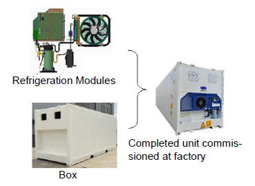
PrimeLINE ONE™ Container
At the Asia Intermodal show, Carrier Transicold introduced a new refrigeration model named the PrimeLINE ONE™ refrigerated container.
The new model is a refrigerated shipping container developed through a joint initiative of Carrier Transicold and Singamas Container Holdings Ltd., a manufacturer of shipping containers.
The PrimeLINE ONE container (Model Number 69NT40-565-250, -500) provides an alternative to bolting a complete refrigeration system onto the front end of the box. The refrigeration system components are built at the Carrier Transicold factory in Singapore and shipped to a new Carrier Transicold factory located adjacent to the Singamas container factory in Qingdao, China.
The system refrigeration components are assembled on-site onto the welded front wall of a specially designed container, within the Carrier Transicold factory. The unit is commissioned right at the factory.
Key PrimeLINE ONE Container Features:
1.Proven performance of the PrimeLINE® refrigeration system. All of the components, controller and control software are identical to the PrimeLINE system, helping to ensure proven performance.
2.Easy maintenance and repairs. All of the components, controller and control software are interchangeable with existing parts of the PrimeLINE system. No special parts are required.
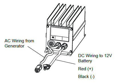
Battery Charger Troubleshooting (30-00460-06)
RG Gensets with PIDs greater than RG2059 (Tier 4), RG1862 (Tier 4i) and UG Gensets greater than UG2019 (Tier 4), UG1820 (Tier 4i) have a new battery charger, part number 30-00460-06. The -06 charger looks similar to the -04 and -05 but are not interchangeable due to internal components. The -06 can be used as a replacement for the -05 with some modification to the plug, but the -05 should not be used as a replacement for the -06.
Tools Required:
•DC Amp Meter / Multimeter (DC Voltage)
Procedure:
1.Follow local lockout / tagout procedures when troubleshooting.
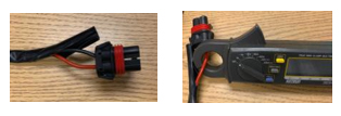
2.Connect a DC current clamp to the Red (+) wire on the DC output harness to the battery.
You may need to slide back or carefully cut back the black tubing covering sleeve to get access to the red wire on the fitting of the current clamp.
3.With the Genset unit off, hold the air intake heater switch on for 30 seconds.
4.Turn the Genset unit on and note the current draw on the current clamp.
|
Current Range |
Action |
|---|---|
|
2A-27A |
No action, charger is operating correctly. |
|
<2A |
Measure battery terminal voltage. If voltage is 13.4-13.7 VDC, then the charger is operating correctly. If voltage is outside of this range, then replace battery charger. |
5.After troubleshooting is complete, tape the tubing back over the wires.
6.If it is determined that the battery charger is bad, it is important to document the amperage and voltage findings on the RMA (return material authorization) to assist with future analysis of the failed part.
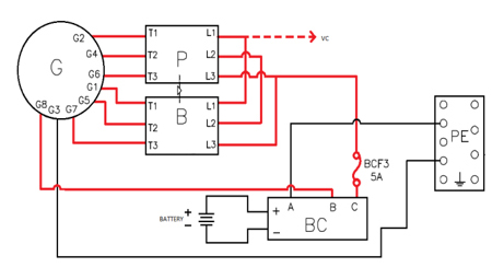
Battery Charger Circuit (Reference)
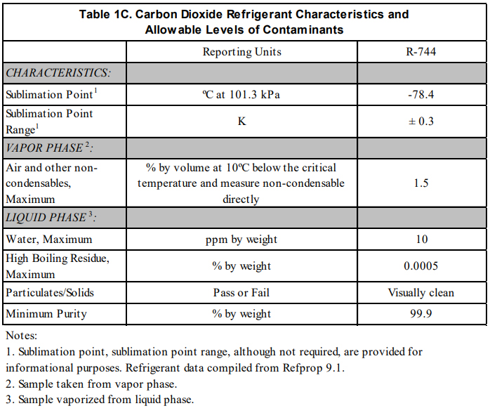
NaturaLINE® CO2 Refrigerant
Carrier Transicold’s NaturaLINE® container refrigeration unit model 69NT-40-601 uses CO2 refrigerant commonly known as R-744. The R-744 used in the NaturaLINE product conforms to Air-Conditioning, Heating and Refrigeration Institute (AHRI) standard 700. By standardizing the purity levels of R-744, this reduces the amount of impurities allowed that may be detrimental to the refrigeration system.
As there are different purity levels of CO2, it is recommended that when purchasing refrigerant, you also receive a Certificate of Conformance.
Tier 4 Genset Voltage Controller
The Voltage Controller (VC), part number 12-00707-03, is used to regulate voltage in order to keep the generator output within ISO limits using the Primary and Boost contactors.
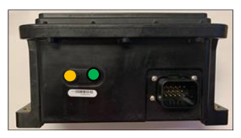
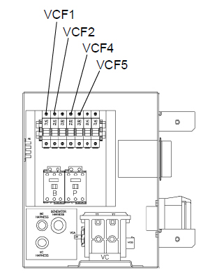
The voltage controller (VC) has one green indicator light and one yellow / amber indicator light along with 4 input fuses. The voltage controller fuses, VCF4 and VCF5 carry the power to the controller, and fuses VCF1 and VCF2 sense the demand on the generator adjusting output voltage accordingly. The green LED light is a signal that the voltage controller is receiving power at voltage controller plug VCA1 and VCA2 on the connector. The yellow / amber light will flash once per second if operating normally. Any other flashing sequence is an indication of a potential problem.
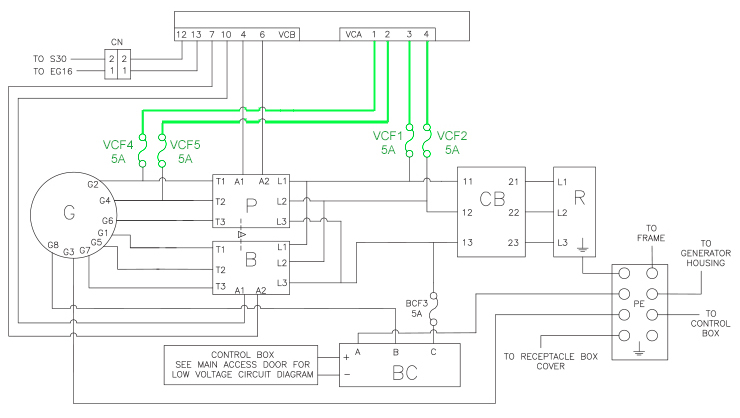
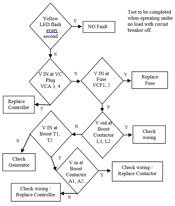
Below is the schematic layout of the inputs and outputs of the voltage controller, along with a general guide to be used in troubleshooting the controller. Follow local lockout / tagout procedures when troubleshooting.
Voltage Controller (VC) Fuses
Voltage Controller (VC) Circuitry
Troubleshooting - No Voltage Output at Startup

Troubleshooting - Rapid Voltage / Power Cycling on Startup (Boost Contactor Engaged)
Automatic Cold Treatment (ACT) Cd51
Cold Treatment has been employed as an effective post-harvest method for the control of Mediterranean and certain other tropical fruit flies. Exposing infested fruit to temperatures of 2.2°C (3.6°F) or below for specific time periods results in the mortality of various life stages for this group of insects.
Automated Cold Treatment (ACT) in the Carrier Transicold unit is a method to simplify the task of completing cold treatment by automating the process of changing the setpoints. ACT is set up through Code Selection Cd51. Refer to Function Code table in operations and service manual for Cd51 menu processing and displays.
Procedure to Set ACT:
1.Enter the required cargo setpoint. It must be lower than the treatment temperature that will be discussed in step 5.
2.Press the CODE SELECT key.
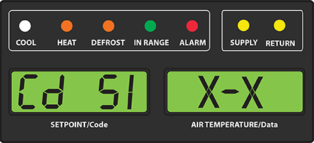
3.Use the Arrow keys to scroll to Cd51, and then press the ENTER key.
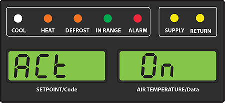
4."ACt" is now displayed in the left display and the right will display "Off". Use the Arrow keys to bring up "On" in the right display and press the ENTER key.
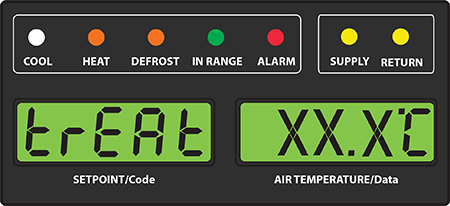
5.“trEAt" is now displayed in the left display and the right will be flashing the last setting (shown as XX.X°C). Use the Arrow keys to select the desired cold treatment setpoint and press the ENTER key.
"trEAt" is the maximum value that the USDA probes need to remain below, to pass the Cold Treatment protocol. For instance, if the treat value is set at 35.0°F (1.7°C) then the USDA probe temperatures must remain below 35.0°F (1.7°C) to pass.
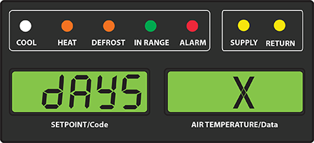
6."dAyS" is now displayed in the left display and the right will be flashing. Use the Arrow keys to select the desired days for cold treatment and press the ENTER key.
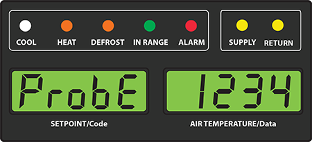
7."ProbE" is now displayed in the left display and the right will display the probe numbers that are connected. Press the ENTER key. For instance, if "1234" is displayed, then all four of the probes are connected.
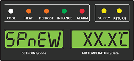
8."SPnEW" is now displayed in the left display and the right will be flashing. Use the Arrow keys to select the desired setpoint after the cold treatment process has successfully completed and press the ENTER key. This would be the final temperature prior to the delivery of the cargo.
9.Cd51 is now displayed in the left display and the right will display days / hours remaining in cold treatment.
Once the cold treatment process has been initiated, setpoint change via the keypad is disabled.
The unit will start to countdown once all detected USDA probes have reached the cold treatment temperature in step 5 above. The cold treatment process will continue until the number of days specified in step 6 is reached. During operation, Cd51 will show the number of days and hours remaining in the cold treatment.
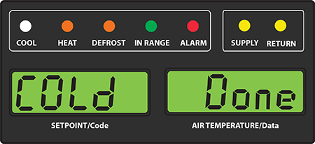
While the unit is operating in ACT mode, the left hand display will alternate between "COLd" and setpoint. The right hand display will alternate between "trEAt" and the cargo temperature. Once the treatment time has been completed, the setpoint temperature will increase to the "SPnEW" setting chosen in step 8.
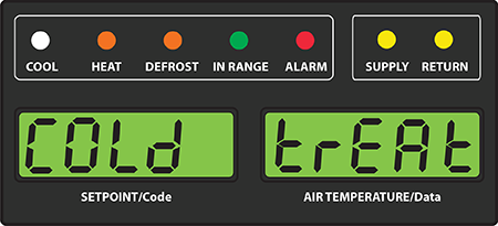
When the cold treatment process is complete, the "SPnEW" setpoint will be displayed in the left hand display and cargo temperature in the right hand display, alternating with "COLd" "Done". "COLd" "Done" will continue to alternate with the setpoint and cargo temperature until ACT is turned off.
ACT can be manually turned off by selecting Cd51, scrolling to "Off" and pressing the ENTER key.
ACT will be automatically turned off with a TripStart, or if a Pretrip is initiated.
Automatic Setpoint Change (ASC/ Cd53) and ACT (Cd51) will not work simultaneously. Setting one will deactivate the other.
USB Adapter for Micro-Link® 3 Controller
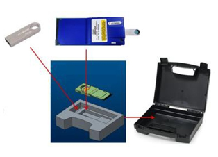
Carrier Transicold recently released a USB to PCMCIA adapter kit, part number 76-50214-02, for use with the Micro-Link®3 controller. This adapter can be used to download data and install software / configuration files using a USB drive. The adapter kit (as pictured) includes a protective carrying case, the PCMCIA to USB adapter, (2) Blank USB Flash Drives and an instruction manual.
The instructions for using the adapter can be found at the Carrier Transicold website in the literature section by selecting Product Type (Containers) / Select Model (All Container Units) / All Documents (Operation). The link is under the Operation heading and is titled 62-12042 ML3 USB Adapter Instructions.
ContainerLINK™ App Update
The ContainerLINK™ mobile app, which was released in May of this year, puts a wealth of technical and troubleshooting information into the hands of refrigeration technicians. Available free on both iOS and Android devices, it offers interactive resources, including service manuals with instructional videos, an alarm code lookup function, conversion tools and warranty information for units being serviced.
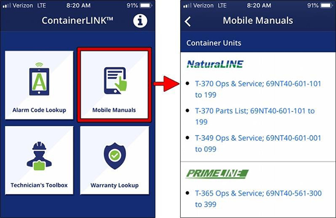
The app contains a "Mobile Manuals" menu that provides access to mobile-optimized service manuals. These manuals include all text and visuals found in the standard printed equipment manuals, with added benefits of search ability, pinch-to-zoom for closer study of detailed schematics and embedded videos that show maintenance procedures.
Mobile-optimized versions require internet access for viewing. In the event that a technician needs off-line access to a manual, the app provides links to download and save the PDF versions of all manuals. PDF manuals are helpful in environments where there may not be cellular or Wi-Fi connections and useful for ship crews that need to repair a refrigeration unit while a container is at sea.
In addition to PDF service manuals, the app now provides access to current and archived issues of the TechLINE newsletter in PDF format. These are also accessible from the Mobile Manuals menu.
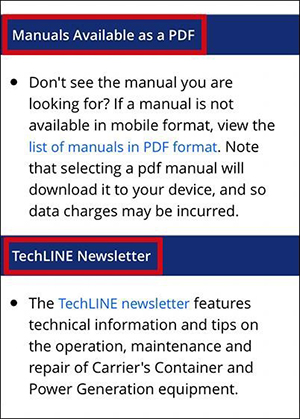
To access PDF service manuals from the Mobile Manuals menu:
1. Scroll down to the heading named “Manuals Available as a PDF”.
2. Select the blue link for the “list of manuals in PDF format”. This opens the PDF manuals list.
To access PDF TechLINE newsletters from the Mobile Manuals menu:
1. Scroll down to the heading named “TechLINE Newsletter”.
2. Select the blue link to open the list of current and archived TechLINE newsletters.
MPR Parts
Over the last few months, there have been a number of incidents with returned parts particularly compressors, microprocessors and motors. For diagnosing any failed part, it is important that packaging is correct and adequate when returning any part, preventing damage not associated to the true failure. The easiest way to achieve this is to establish a standard practice of reusing the original packaging for the return part.
Compressors - It is recommended that compressors are unbolted from the original base pallet and that all packaging is retained and used to prepare the failed compressor for return. Install seal plugs into refrigerant connections and bolt the compressor back onto the base pallet. Compressors must NEVER be shipped laying down in a plastic bag!
Microprocessors - Electronic parts should always be kept in an anti-static bag to prevent static damage to internal parts and then placed back into the original external packaging. They have an internal lithium battery, and must be shipped with the 'Lithium battery warning' label, clearly visible.
Motors - Motors should be packaged in the original packaging, INCLUDING, the polystyrene supports, which hold the motor and prevent it from rolling damaging the shipping box
Trip Start Definition
A Trip Start is an event posted in the DataCorder. Typically this event is posted to notify the customer when a trip has been started. It also places a marker in the DataCorder, so the user can download the information for one trip. When a Trip Start is set, the unit may be set back to the units / customers default settings (i.e. defrost to AUTO, ASC to OFF, etc.).
A trip start event can be posted in 4 ways:
1.User manually enters a Trip Start via the keypad.
2.A successful AUTO PTI has been run.
•If model configuration variable 42 is 'out' a trip start event will not occur with an AUTO PTI.
3.A remote command is sent through the RMM device (if equipped).
4.On power up, if the unit has been off for greater than 7 days. The 7 days was selected based on a unit that has been off for 7 days. With this the assumption is that it has no cargo loaded and will be starting a new trip.
For specific details on the model configuration / default settings, contact your Regional Field Service Engineering Manager.
Listed below are the remaining 2018 instructor led courses. The 2019 courses will be posted by the end of November. If you would like to have a course in your area, now is the time to discuss this with your Field Service Engineering Manager. Please note, all scheduled courses are subject to a minimum enrollment of 12 students.
|
Course |
Location |
Dates |
|---|---|---|
|
1 Week Container Technician Certificate Course |
Karachi, Pakistan |
11/12/2018 -- 11/16/2018 |
|
3 Day Container Technician Certificate Course |
Kaohsiung, Taiwan |
11/13/2018 -- 11/15/2018 |
|
3 Day Container Technician Certificate Course |
Abidjan, Ivory Coast |
11/19/2018 -- 11/21/2018 |
|
1 Week Container Technician Certificate Course |
Wilmington, IL |
12/03/2018 -- 12/07/2018 |
Listed below is the website that can be checked for the upcoming hands on schools along with a listing of the available On-Line courses. Chinese Mandarin has been recently released, Spanish will be released prior to the end of the year.
Listed are the software release versions for operating and working with Carrier Transicold units. Prior to upgrading software on units, you should seek agreement from the equipment owners.
Recip Unit (ML2/1207, ML2i / 5159, ML3, 5167)
Scroll Unit (ML2i, 5360 /ML3, 5369)
NaturaLINE (ML3, 5707)
Controlled Atmosphere - 3115
DataLINE 3.2, DataBANK 0513.
Menu - 0116, Software cards with revision greater than 5159 or 5361 must have menu 0116 or an error could occur.
After completing a software upgrade, verify the user selections (i.e. defrost interval, set point, etc.).
TechLINE is a publication of Carrier Transicold.
Editor / Contributor: Perry Hoover
Contributors: Oh Boon San, Barry Hofsdal, Kurt Handley, David Whyte, Tom Graf, Matt Schlote
Thanks to all who supported this release.