July 2018 Issue
Inside This Issue:
TripWise Option for PrimeLINE® and PrimeLINE® EDGE Units
Carrier Transicold has introduced a new premium option to its reefers called TripWise™. TripWise is software logic that runs in the background during every voyage and will let you know whenever a standard pre-trip inspection (PTI) is needed.
The tests run in the background and are similar to those completed as part of the standard PTI selection, which includes the following:
•Alarm Presence
•Evaporator Motor Current
•Heater Current
•Condenser Motor Current
•Compressor Current
•Humidity Sensor
•Supply / Return Sensors
•Evaporator Temperature and Pressure Sensors
•Defrost Temperature Sensor
•Electronic Expansion Valve
•RMU Presence
•Compressor Test
•Digital Loader / Unloader Valves
•Economizer Valve
•Temperature Control
•Suction / Discharge Temperature and Pressure
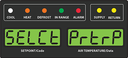
To check the status of the container, press the PRE-TRIP key on the keypad. The message “SELCt | PrtrP” will appear on the display module, alternating with one of four messages listed below that shows TripWise status. Pressing the ENTER key while “SELCt | PrtrP” is displayed will enter into the pre-trip test menu. Pressing the arrow keys will navigate through the standard PTI test selections menu.
trIPW | PASS
The container should be ready for use after the operator has conducted a visual inspection. Standard PTI is not required.
trIPW | CHECK
If any TripWise test(s) execute and do not meet the pass / fail requirements, It is recommended to pre-trip the unit following customer-specific guidelines prior to the unit's next trip.
trIPW | EX (Expired)
It is recommended to pre-trip the unit following customer-specific guidelines prior to the unit's next trip.
trIPW | OFF
The TripWise option is turned off. To activate, scroll to code select 65 (Cd65).
By pressing code select 65 "-----"," OFF" or "ON" will be displayed, in which case the user can switch from one to the other by pressing ENTER followed by the arrow and ENTER to select the desired option. If "ON" is selected, the user then sets the expiration interval in days (2 through 365 in 1 day increments) by pressing the arrow key to the desired interval followed by the ENTER key. The expiration interval is the maximum days allowed between running each test, i.e. if days are set to 30 and the low speed evaporator fan test has not run within those 30 days, the TripWise™ expired message will be displayed. If the TripWise expired message is displayed, it is recommended that a PTI be conducted following customer specific guidelines prior to the next trip.
If "-----" is displayed, the TripWISE function option is not active on the unit. To add this option to your unit, the equipment owner would need to contact their Regional Carrier Sales Manager.
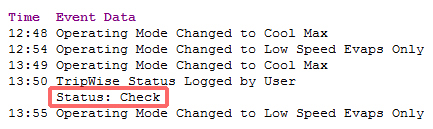
A TripWise status event will be recorded in the DataCorder recorder when the PTI is selected. In the current DataLINE® software release, the event will show the status of the unit.
TripWise Status in DataCorder
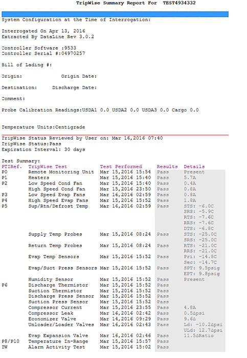
In DataLINE version 3.2, perform an all data download - select from the drop down menu “TripWise Summary” then select a date in “User Logged Events”. This will generate the status / results in a DataLINE TripWise Summary Report.
TripWise Summary Report
Humidity Sensor Location
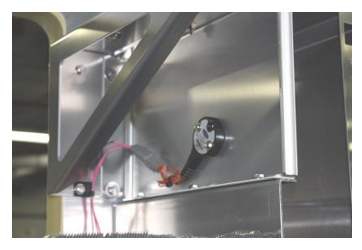
Starting in July 2016 production, PID number NT2750 and greater, the humidity sensor (12-00745-00) was moved from the return air grill (refer to Figure 1) to the evaporator side wall under the evaporator motor (refer to Figure 2), making it more serviceable.
Figure 1: Humidity Sensor Location - Previous
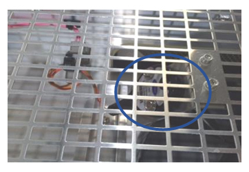
Figure 2: Humidity Sensor Location - New
Humidity Sensor Troubleshooting
The following procedure has been released as a follow-up to the June 2014 TechLINE article in an effort to ease the troubleshooting of the humidity sensor. When using this procedure and working on a unit, you should always follow the local lockout / tagout procedures in your area.
Items Required:
•One 7/16” socket wrench or nut driver.
•One 1/4” socket wrench or nut driver.
•One clean, clear water bottle with a minimum 6 cm (2.5 in) opening and capacity to hold 500 ml (16.9 oz).
•100 ml (3.4 oz) of fresh water - distilled if available.
•50 gm of Salt (NaCl).
Procedure:
1.Remove the left Upper Fresh Air Makeup Vent panel.
2.Remove the humidity sensor from the mounting hardware and bring to the front of the access panel.
3.Disconnect the humidity sensor from the harness.
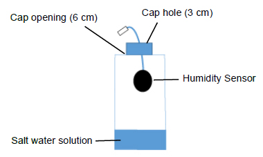
4.Drill a 3 cm (1.25 in) hole in the cap of a bottle.
5.Pour approximately 100 ml (3.4 oz) of water into the empty clean bottle.
6.Add salt to the water until it is present at the bottom of the bottle.
7.Cap the bottle and tape over the drilled hole.
8.Shake the bottle until the salt dissolves and water is saturated.
NOTE: To ensure saturation, add additional salt until it settles at the bottom without dissolving while shaking.
9.Remove the cap and insert the humidity sensor into the bottle through the bottle opening and pull the connector back through the drilled hole in the cap. Then, secure the cap and seal the wire going through the cap.
NOTE: Make sure that the sensor is not at all in contact with the salt water.
10.Allow the saturated salt mixture to settle for approximately ten minutes.
11.Reconnect the humidity sensor to the harness and power the reefer unit on.
12.Press the CODE SELECT key on the keypad.
13.Use the Arrow keys until “Cd17” is displayed then press the ENTER key. This displays the humidity sensor reading.
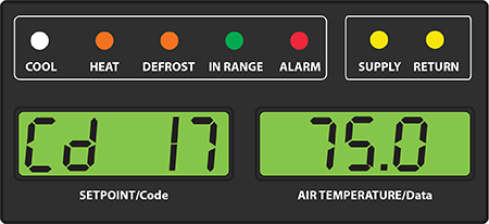
14.Verify the reading is between 60% and 85% relative humidity.
15.If the humidity sensor display is outside of this range, reconfirm the salt mixture and retest. If not in range, replace the sensor at the next opportunity.
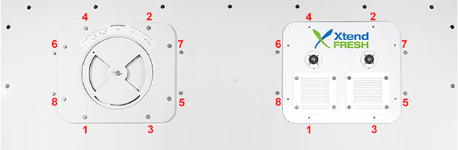
16.Wipe clean and reinstall the humidity sensor and access panel. Torque the access panel hardware to 69 kg-cm (60 in.-lbs.) using a crossing pattern similar to the numbering below.
17.If the panel gasket is damaged and needs to be replaced, use the following part numbers:
•42-00296-01: Standard Panel Gasket
•42-00823-00: XtendFRESH Panel Gasket
PrimeLINE R-513A-Ready Units
Carrier Transicold recently added to its model listings a R-513A-ready PrimeLINE® unit shipped with R-134a for field conversion to R-513A at a later date as requested by the owner of the equipment. Refrigerant R-513A is an azeotrope blend containing R-1234yf and R-134a (56%wt / 44%wt).
The difference between the base R-134a unit and the R-513A-ready unit is the compressor. A new part number 18-10178-20 for R-513A-ready units was added. To simplify the identification of an R-513A-ready compressor in the field, we have placed a green dot on the top of the compressor on the DUV fitting. This compressor can be used as a general replacement for any standard PrimeLINE unit.

As a means of identifying R-513A-ready units, container model number series 69NT40-561-500 has been assigned to a unit with this option.
To convert a R-513A-ready unit, the technician will need to recover refrigerant, change the filter drier, and charge the unit with liquid only as R-513A is a blend. Charging or topping off as a vapor will result in an incorrect mixture of charge in the system. Refrigerant charge amount is the same in both. Upon completion, the technician will need to change the refrigerant labels (76-50235-00) on the front of the unit indicating the change in refrigerant.
To convert an operational OEM R-134a PrimeLINE unit (non R-513A-ready), Carrier recommends that the compressor be changed to a R-513A-ready compressor (18-10178-20).
ContainerLINK™ App
The ContainerLINK™ app is available free for download through the Apple App Store and Google Play Store. The app offers interactive resources, including service manuals with instructional videos, an alarm code lookup function, conversion tools in the technician's tool box and warranty information inclusive of recently completed work for units being serviced.
For more information about Carrier Transicold's products and services for container refrigeration, visit www.transicold.carrier.com.

XtendFRESH™ Operators Guide (62-12065)
A general user's guide is now available online for the operation and troubleshooting of alarms on the XtendFRESH™ unit. The guide provides recommended actions that can be taken if replacement parts are not readily available.
The operators guide can be found at the following website:
https://www.carrier.com/container-refrigeration/en/worldwide/service-support/
in the Literature section under Search by Product Type: Options / XtendFRESH / All Documents.
XtendFRESH Troubleshooting Guide
|
AL07 |
MANUAL FRESH AIR VENT (FAV) OPEN |
|
Cause |
For units equipped with XtendFRESH and a Vent Position Sensor, the controller will monitor the manual fresh air opening at a pre-determined time. If during this time the fresh air vent is open and XtendFRESH is active, an alarm will be generated. If alarm is active, the controller monitors the manual fresh air once per hour. Upon clearing the alarm, the controller goes back to monitoring at the pre-determined time. |
|
Component |
Vent Position Sensor (VPS) |
|
Troubleshooting |
Manually reposition vent to 0% and confirm using Cd45. If Cd45 is not reading 0%, perform a calibration of the panel. If unable to obtain zero reading, replace defective VPS. If unit is loaded, ensure vent is closed. Note and replace VPS on next PTI. The alarm will not affect the XtendFRESH system from operating. |
|
AL09 |
O2 SENSOR FAILURE |
|
Cause |
Triggered anytime the O2 sensor reading is outside of the normal operation range, after an initial signal was detected. |
|
Component |
O2 Sensor, O2 Amplifier, Sensor Switch Module (if equipped) |
|
Troubleshooting |
Check Cd44 and scroll down to 02V. The O2 sensor output will be displayed in millivolts (130mV to 4100mV). Switch equipped: If voltage is not present at Cd44 and a sensor switch module is installed, check for O2 voltage on black wire connected to the sensor switch module, connecting ground of meter to TP9. If the voltage is in the 130mV to 4.1V range, directly wire black wire to KD04. This may cause an AL07 depending on O2 reading but XtendFRESH will operate normally. If no voltage on black wire, proceed to next step. Check wiring (refer to schematic), and correct if found mis-wired. If O2 sensor is available, remove upper fresh air panel and evaporator motor and replace sensor. If after replacing sensor AL09 continues, replace amplifier. If parts are not available, turn XtendFRESH option off (Cd43) and open the Manual Fresh Air Vent. |
|
AL10 |
CO2 SENSOR FAILURE |
|
Cause |
Triggered anytime the CO2 sensor reading is outside of the normal operation range, after an initial signal was detected. |
|
Component |
CO2 Sensor |
|
Troubleshooting |
Check the voltage at MC5 to ground pin on TP9. (1 - 4.7 vdc) Check wiring (refer to schematic), and correct if found mis-wired. If part is available, remove upper fresh air panel and evaporator motor; replace sensor. If no part is available, take no action and service at next PTI. XtendFRESH will continuously run the scrubber. O2 level will be controlled with the opening and closing of the fresh air vents as required. |
|
AL29 |
LOSS OF ATMOSPHERIC CONTROL |
|
Cause |
Triggered whenever the CO2 level is above its upper limit by 1% for 60 minutes. Or, when O2 level is greater than 1% below its set point for longer than 30 minutes after the unit has been in range. The alarm is triggered off when the levels return to within the normal range. |
|
Setup |
Run Cd43 test mode for troubleshooting the below components. At the end of test mode, a sensor calibration will be attempted. Under loaded box conditions, the sensor values may post “No Cal” or “CAL FAIL”. Results from original calibration will be retained. If test mode times out, then hold the code select key for 3 seconds to exit test mode. |
|
Troubleshooting |
If components do not energize, check FX1 and FX2 for power (460 VAC). If fuse is open, check heater continuity (XHT1 to ground). Must be greater than 1 mega ohm. If less than 1, disconnect the heater at XHT1 and XHT2. Replace fuse. Unit will control on fresh air solenoids. |
|
Component |
Solenoid Air Vents |
|
Troubleshooting |
Visually inspect to see if solenoid valves are opening air vents. If vents open, troubleshoot the next component. If vents do not open, continue with troubleshooting below. Check FX4 fuse for power (~20 volts dc). If fuse is open, check wiring and or replace solenoid if part is available. If no part is available, open manual fresh air vent. |
|
Component |
XtendFRESH Fan(s) / XtendFRESH Scrubber Motor |
|
Troubleshooting |
Visually inspect to see if the XtendFRESH Fan(s) are running (air blowing on left, intake on right), check current draw of motor at the XST1 (~ 40 to 200 milliamps / contactor load side). Troubleshoot the non-operating component. If both are running, proceed to next component. Verify XS contactor is pulling in. If not, check FX6 fuse for power (24 VAC). If not, check power at controller KB4. Check FX3 fuse for power (~20 vdc). If no power, replace fuse. If fuse opens a second time, take no further action. O2 level will be controlled with the opening and closing of the fresh air vents. If part is available, replace either fan or scrubber motor. Fan is replaceable from the front on a loaded unit; Scrubber motor is not. If no part is available or accessible, take no action and service at next PTI. O2 level will be controlled with the opening and closing of the fresh air vents. |
|
Component |
Heater |
|
Troubleshooting |
Verify XH contactor is pulling in. If not, Check FX6 for power (24 VAC). If open ohm contactors XHA1 and XSA1 to ground. Replace (12 Amp) contactor. If contactor is pulling, power unit off and check heater resistance from XH1to XH2 (450 to 500 ohms). If heater is outside of the range, disconnect heater at XHT1 and XHT2 and replace at next PTI. Unit will control on fresh air solenoids. |
|
AL62 |
O2 OUT OF RANGE |
|
Cause |
This is a notification alarm and does not pose a risk to fresh produce. AL62 is triggered when there is an indication that the O2 level is rising after reaching its setpoint (+1%). If O2 level exceeds 4% above setpoint, the alarm is activated. The alarm does not activate if the unit was pre-tripped or trip started between last reaching its O2 setpoint and exceeding the plus 4%, or if power has been turned off for eight hours. The alarm is deactivated if O2 drops below setpoint (+ 1%) or if a pre-trip or trip start is performed. |
|
Component |
Scrubber Failure |
|
Troubleshooting |
Refer to AL29 Scrubber component above. |
|
Component |
XtendFRESH Solenoid Valves |
|
Troubleshooting |
Refer to AL29 Solenoid Air Vent component above. |
|
Component |
Container Air Tightness |
|
Troubleshooting |
Seal container where possible (access panels, rear doors, mounting hardware, etc). |
|
AL96 |
SCRUBBER ROATION FAILURE - OPTIONAL FEATURE |
|
Cause |
Feedback from the Scrubber Motor to the controller not detected |
|
Scrubber Motor |
|
|
Troubleshooting |
Run Test Mode and verify scrubber bed is turning. If back panel cannot be removed to check, verify the scrubber amperage consumption, read at XS contactor wire XSL1. If between 40 and 200mA, motor is rotating properly. If no current detected, check and replace FX3. If current spiking to 350mAps for 2 seconds then dropping to 90mAmps, the scrubber motor is located. If scrubber motor is locked, further inspection of the scrubber bed is required. Unit will control CO2 with the fresh air solenoid when this alarm occurs if scrubber inaccessible. |
|
Component |
Ground Interface Module (GIM) |
|
Troubleshooting |
Once it has been verified that the scrubber motor is rotating, check the wiring connections to the GIM module. If all wires secured properly, replace the GIM module if one is available. If not, the unit will control CO2 using the fresh air solenoids. |
NaturaLINE® Parts / Tools
As the NaturaLINE® units are becoming more globally available in the field, it is important to ensure that, both parts and tools are available. Following is a listing of the parts and tools required:
|
69NT40-601 |
||||
|---|---|---|---|---|
|
Part Number |
Description |
Stock QT |
001 to 099 |
101 to 199 |
|
76-00892-06 |
Suction Pressure Transducer (SPT) Service Kit |
1 |
X |
X |
|
76-00892-07 |
Pressure Transducer (DPT, FPT) Discharge and Flash Tank Service Kit |
1 |
X |
X |
|
76-00892-08 |
High Pressure Switch (HPS) Service Kit |
1 |
X |
X |
|
14-00382-00 |
Electronic Exp. Valve (EVXV) |
1 |
X |
X |
|
14-00394-20 |
Economizer Solenoid Coil (ESV, USV) |
1 |
X |
X |
|
14-00396-10 |
High Pressure Expansion Valve (HPXV) Coil |
1 |
X |
X |
|
14-00406-01 |
Filter Drier |
1 |
X |
X |
|
10-00482-20SV |
VFD Fan Replacement Kit |
1 |
X |
X |
|
79-04023-21 |
Service Compressor Kit |
1 |
X |
X |
|
22-04214-02 |
VFD Interface Module |
1 |
X |
X |
|
54-00640-20 |
Gas Cooler Fan Motor |
1 |
X |
|
|
54-00677-20 |
Gas Cooler Fan Motor |
1 |
X |
|
|
Part Number |
Description |
Qty |
|
07-00414-00 |
Electronic Vacuum Gauge (MICRONS) |
1 |
|
07-00512-00 |
Magnet (Solenoid Valve Manual Opening Coil) |
2 |
|
07-00527-00 |
CO2 Gauge Set |
1 |
|
14-00396-20 |
Magnet (Expansion Valve Manual Opening Coil) |
1 |
|
R744 |
AHRI 700 Standard |
1 |
For a complete listing of parts, refer to the operations and service manual (T-349 and T-370) or contact your regional service engineering manager.
Global Training Schedule, 2018 Q3/Q4
Listed below are the instructor-led training courses scheduled through Q4 2018. Courses are subjected to a minimum requirement of 12 students. Courses marked with the asterisk are technician certification courses. The attendees of the course need to pass both the hands-on troubleshooting and written exam.
Approximately 30 days prior to the class start date, registered students will receive an email confirming the class is being conducted along with logistical information. You should not make travel arrangements to attend the class until after you have received a confirmation email.
|
Region |
Start Date |
Course Description *Certificate |
Location |
|---|---|---|---|
|
APO |
7/17/2018 |
3-Day Container Technician * |
Vladivostok, Russia |
|
APO |
7/30/2018 |
1-Week Container Technician * |
Chennai, India |
|
APO |
9/11/2018 |
2-Day Container Technician * |
Tauranga, New Zealand |
|
APO |
9/19/2018 |
3-Day Container Technician * |
Nagoya, Japan |
|
APO |
10/9/2018 |
3-Day Container Technician * |
Suva, Fiji |
|
APO |
10/23/2018 |
3-Day Container Technician * |
Xiamen, China |
|
APO |
11/5/2018 |
1-Week Container Technician * |
Karachi, Pakistan |
|
APO |
11/13/2018 |
3-Day Container Technician * |
Kaohsiung, Taiwan |
|
EMEA |
8/6/2018 |
3-Day Container Technician * |
Abidjan, Ivory Coast |
|
EMEA |
8/21/2018 |
3-Day Container Technician * |
Odessa, Ukraine |
|
EMEA |
8/28/2018 |
3-Day Container Technician * |
Tangier, Morocco |
|
EMEA |
9/4/2018 |
3-Day Container Technician * |
Le Havre, France |
|
EMEA |
9/11/2018 |
2-Day Container Technician * |
Cape Town, South Africa |
|
EMEA |
9/18/2018 |
3-Day Container Technician * |
Izmir, Turkey |
|
EMEA |
9/25/2018 |
2-Day Container Technician * |
Bremerhaven, Germany |
|
EMEA |
10/4/2018 |
2-Day Container Technician * |
Dubai, United Arab Emirates |
|
EMEA |
10/9/2018 |
3-Day Container Technician * |
Haifa, Israel |
|
EMEA |
10/16/2018 |
2-Day Container Technician * |
Hamburg, Germany |
|
LAO |
7/30/2018 |
3-Day Container Technician * |
Paita, Peru |
|
LAO |
8/14/2018 |
3-Day Container Technician * |
Montevideo, Uruguay |
|
LAO |
8/20/2018 |
1-Week Container Technician * |
Puerto Limon, Costa Rica |
|
LAO |
9/17/2018 |
1-Week Container Technician * |
Progreso, Mexico |
|
LAO |
9/25/2018 |
3-Day Container Technician * |
Guayaquil, Ecuador |
|
LAO |
10/3/2018 |
3-Day Container Technician * |
Kingston, Jamaica |
|
LAO |
10/22/2018 |
3-Day Container Technician * |
Buenos Aires, Argentina |
|
LAO |
10/22/2018 |
3-Day Container Technician * |
Ensenada, Mexico |
|
LAO |
10/25/2018 |
2-Day Genset |
Ensenada, Mexico |
|
LAO |
11/5/2018 |
3-Day Container Technician * |
Rio Grande, Brazil |
|
NAO |
8/6/2018 |
2-Day Container Technician * |
Long Beach, CA |
|
NAO |
8/9/2018 |
2-Day Container Technician * |
Oakland, CA |
|
NAO |
8/13/2018 |
2-Day Container Technician * |
Seattle, WA |
|
NAO |
10/8/2018 |
1-Week Container Technician * |
Long Beach, CA |
|
NAO |
11/12/2018 |
1-Week Container Technician * |
Jacksonville, Florida |
APO - Asia Pacific Operations
EMEA - Europe Middle East Africa
LAO - Latin America Operations
NAO - North America Operations
Class dates and or locations can change throughout the year. It is recommended that you periodically go to the website to check on any that may have been added, revised or removed.
Listed are the software release versions for operating and working with Carrier Transicold units. Prior to upgrading software on units, you should seek agreement from the equipment owners.
Recip (ML2i / 5159, ML3, 5167), Scroll (ML2i, 5360 /ML3, 5369)
Reciprocating Unit (ML2) - 1207, NaturaLINE (ML3, 5706)
Controlled Atmosphere - 3115
DataLINE 3.2, DataBANK 0513.
Menu - 0116, Software cards with revision greater than 5159 or 5361 must have menu 0116 or an error could occur.
After completing a software upgrade, verify the user selections (i.e. defrost interval, set point, etc.).
TechLINE is a publication of Carrier Transicold.
Editor / Contributor: Perry Hoover
Contributors: Oh Boon San, Barry Hofsdal, David Whyte, Tom Graf, Matt Schlote
Thanks to all who supported this release.