November 2017 Issue
Inside This Issue:
TechLINE® Academy
For over 50 years Carrier Transicold has led the container refrigeration industry with quality innovations. That trend continues with the introduction of the TechLINE® Academy. Designed to appeal to today’s high tech learners, the revised curriculum and online offerings establish a new standard for technician training.
These significantly enhance the curriculum by requiring participants to demonstrate a level of proficiency upon completion to reflect Carrier Transicold’s high standard of excellence.
Associate Certification: Aimed at the new technician just starting in the industry it can be obtained by completing the specified online classes or completing a 3 day Carrier Container Associate Certificate class. Certification can be applied for, after having completed 6 months hands on work, on Carrier Container Refrigeration units.
Technician Certification: Because of the varying levels of experience within the industry and to provide everyone an opportunity to transition to Technician Container certification, there are a number of options available. Whichever option you choose to complete your Technicians Certification, it requires attendance at an instructor led class and a pass of both a written and practical exam which are given at the end of this course.
It should be noted that there is an option for experienced Technicians who have already been in the industry for many years to be certified, but this option will only be available until the end of 2018.
MasterTech Certification: Technicians can continue to advance their knowledge beyond the basics by completing update modules on additional models, unit options and features. Once these additional modules have been completed and a Technician has at least 5 years’ experience, they can make arrangements to take the written and practical MasterTech exam. Full details will become available in 2018.
XtendFRESH™ Troubleshooting
The XtendFRESH™ controlled atmosphere option alarms are AL07, AL09, AL10, AL29, AL62 and AL96. In an effort to assist in troubleshooting, we have listed general guidelines for each alarm along with a recommended actions to be taken. For additional technical assistance, refer to the XtendFRESH T-366 service manual.
XtendFRESH Troubleshooting Guide
|
Manual Fresh Air Vent Open |
|
|
Cause |
For units equipped with XtendFRESH and a Vent Position Sensor, the controller will monitor the manual fresh air opening at a pre-determined time. If during this time the fresh air vent is open and XtendFRESH is active, an alarm will be generated. If alarm is active, the controller monitors the manual fresh air once per hour. Upon clearing the alarm, the controller goes back to monitoring at the pre-determined time. |
|
Component |
Vent Position Sensor (VPS) |
|
Troubleshooting |
Manually reposition the vent to 0% and confirm using Cd45. If Cd45 is not reading 0%, perform a calibration of the panel. Refer to Vent Position Service in the (T-340, T-362, T-365) operations & service manual. If a zero reading can not be obtained, replace the defective VPS. If the unit is loaded, ensure the vent is closed. Note and replace the VPS on the next PTI. The alarm will not affect the XtendFRESH system from operating. |
|
O2 Sensor Failure |
|
|
Cause |
Triggered anytime the O2 sensor reading is outside of the normal operation range, after an initial signal was detected. |
|
Component |
O2 Sensor, O2 Amplifier, Sensor Switch Module (if equipped) |
|
Troubleshooting |
Check Cd44 and scroll down to 02V. The O2 sensor output will be displayed in millivolts (130mV to 4100mV). Switch equipped: If voltage is not present at Cd44 and a sensor switch module is installed, check for O2 voltage on the black wire connected to the sensor switch module, connecting ground of meter to TP9. If the voltage is in the 130mV to 4.1V range, directly wire the black wire to KD04. This may cause an AL07 depending on O2 reading but XtendFRESH will operate normally. If no voltage on the black wire, proceed to next step. Check wiring (refer to schematic), and correct if found mis-wired. If O2 sensor is available, remove the upper fresh air panel and evaporator motor and replace the sensor. If after replacing the sensor AL09 continues, replace the amplifier. If parts are not available, turn the XtendFRESH option off (Cd43) and open the Manual Fresh Air Vent. |
|
CO2 Sensor Failure |
|
|
Cause |
Triggered anytime the CO2 sensor reading is outside of the normal operation range, after an initial signal was detected. |
|
Component |
CO2 Sensor |
|
Troubleshooting |
Check the voltage at MC5 to the ground pin on TP9 (1 - 4.7 vdc). Check wiring (see schematic), and correct if found mis-wired. If sensor part is available, remove the upper fresh air panel and evaporator motor; replace the sensor. If no part is available, take no action and service at the next PTI. XtendFRESH will continuously run the scrubber. O2 level will be controlled with the opening and closing of the fresh air vents as required. This alarm is triggered off when voltage is within operating range. |
|
Loss of Atmospheric Control |
|
|
Cause |
Triggered whenever the CO2 level is above its upper limit by 1% for 60 minutes. Or, when the O2 level is greater than 1% below its setpoint for longer than 30 minutes after the unit has been in range. The alarm is triggered off when the levels return to within the normal range. |
|
Setup |
Run Cd43 Test mode for troubleshooting the XtendFRESH mechanical components. At the end of Test mode, a sensor calibration will be attempted. Under loaded box conditions, the sensor values may post “No Cal” or “CAL FAIL”. Results from original calibration will be retained. If Test mode times out, then hold the CODE SELECT key for 3 seconds to exit Test mode. |
|
Troubleshooting |
If components do not energize, check FX1 and FX2 for power (460 VAC). If the fuse is open, check heater continuity (XHT1 to ground). Must be greater than 1 mega ohm. If less than 1, disconnect the heater at XHT1 and XHT2. Replace the fuse. The unit will control on fresh air solenoids. |
|
Component |
Solenoid Air Vents |
|
Troubleshooting |
Visually inspect to see if the solenoid valves are opening air vents. If vents are open, troubleshoot the next component. If vents do not open, continue with troubleshooting below. Check FX4 fuse for power (~20 volts dc). If fuse is open, check wiring and or replace solenoid if part is available. If no part is available, open the manual fresh air vent. |
|
Component |
XtendFRESH Fan / XtendFRESH Scrubber Motor |
|
Troubleshooting |
Visually inspect to see if the XtendFRESH Fan(s) are running (air blowing on left, intake on right). Check current draw of the motor at the XST1 (~40 to 200 milliamps / contactor load side). Troubleshoot the non-operating component. If both are running, proceed to next component. Verify the XS contactor is pulling in. If not, check the FX6 fuse for power (24 VAC). If not, check power at controller KB4. Check FX3 fuse for power (~20 vdc). If no power, replace fuse. If fuse opens a second time, take no further action. O2 level will be controlled with the opening and closing of the fresh air vents. If part is available, replace either fan or scrubber motor. Fan is replaceable from the front on a loaded unit; Scrubber motor is not. If no part is available or accessible, take no action and service at next PTI. O2 level will be controlled with the opening and closing of the fresh air vents. |
|
Component |
Heater |
|
Troubleshooting |
Verify the XH contactor is pulling in. If not, check FX6 for power (24 VAC). If open ohm contactors XHA1 and XSA1 to ground. Replace (12 Amp) contactor. If contactor is pulling, power unit off and check heater resistance from XH1 to XH2 (450 to 500 ohms). If heater is outside of the range, disconnect heater at XHT1 and XHT2 and replace at next PTI. The unit will control on fresh air solenoids. |
|
O2 Out of Range |
|
|
Cause |
This is a notification alarm and does not pose a risk to fresh produce. AL62 is triggered when there is an indication that the O2 level is rising after reaching its setpoint (+ 1%). If O2 level exceeds 4% above setpoint, the alarm is activated. The alarm does not activate if the unit was pre-tripped or trip started between last reaching its O2 setpoint and exceeding the plus 4%, or if power has been turned off for eight hours. The alarm is deactivated if O2 drops below setpoint (+ 1%) or if a pre-trip or trip start is performed. |
|
Component |
Scrubber Failure |
|
Troubleshooting |
Follow troubleshooting of the Scrubber Motor as listed in the AL29 alarm. The Scrubber Motor may have failed. |
|
Component |
XtendFRESH Solenoid Valves |
|
Troubleshooting |
Follow troubleshooting of the Solenoid Air Vent as listed in the AL29 alarm. |
|
Component |
Container Air Tightness |
|
Troubleshooting |
Seal the container where possible (access panels, rear doors, mounting hardware, etc). |
|
Scrubber Rotational Failure - optional feature |
|
|
Cause |
Feedback from the Scrubber Motor to the controller is not sensed when the motor is turning. |
|
Component |
Scrubber Fuse |
|
Troubleshooting |
Check for a blown scrubber fuse. Replace if necessary. |
|
Component |
Scrubber Motor |
|
Run Test Mode and verify the scrubber bed is turning. If the back panel can not be removed to check, verify the scrubber amperage consumption, read at XS contactor wire XSL1. If between 40 and 200mA, motor is rotating properly. If no current is detected, check and replace FX3. If current is spiking to 350mA for 2 seconds then dropping to 90mA, the scrubber motor is locked. If the scrubber motor is locked, then further inspection of the scrubber bed is required. The unit will control CO2 with the fresh air solenoid when this alarm occurs if the scrubber is inaccessible. If the Scrubber Motor is not operating, follow the troubleshooting flowchart in the (T-366) XtendFRESH manual and take appropriate action. |
|
|
Component |
Ground Interface Module (GIM) |
|
Troubleshooting |
Once it has been verified that the scrubber motor is rotating, check the wiring connections to the GIM module. If all wires are secured properly, replace the GIM module if one is available. If not, the unit will control CO2 using the fresh air solenoids. |
Understanding Alarm 23 (AL23)
Alarm 23 has been used for three different alarm triggers depending on unit model. This has led to some confusion when technicians are troubleshooting the alarm. To troubleshoot an AL23 the first step is to identify what model unit you have. As with all troubleshooting, it is essential to start with verifying the correct configuration is installed and the latest recommended software version is installed. The latest service manual for each of the units is available on the Carrier Transicold Container website.
Identify Alarm 23 Trigger:
|
Controller |
ML1 |
ML2 |
ML2i / ML3 |
ML2i / ML3 |
|---|---|---|---|---|
|
Container |
69NT40-414, -434, -441, -444, -449, -454, & -459 |
69NT40-489 & -501 |
ThinLINE 69NT40-511, -521, & -541-000 -299 |
EliteLINE: 69NT40 (or 20) -531 & -551 |
|
Alarm 23 |
Compressor internal protector (IP) |
Auto Transformer internal IP, if equipped |
KA2 - KB10 Jumper Disconnected |
Loss of Phase B |
Troubleshooting for Compressor IP:
The compressor internal protector (IP) is a thermal device that opens a set of contacts, when the motor temperature gets too high. You can determine if the IP is open by ohming across the IP. Select the correct unit schematic for proper connection points. In some cases servicing the unit to ensure it is functioning properly can address this alarm. Clean the condenser coil so the unit can properly remove heat, ensure the system is properly charged to provide refrigerant to help cool the compressor, and verify input power quality. If these don’t resolve the issue proceed with troubleshooting other components that can cause the compressor to overheat, for example the quench valve.
Troubleshooting for Auto Transformer IP:
Some earlier models have an auto transformer with an internal protection to prevent overheating. The alarm will reset once the transformer has been given a chance to cool and the IP resets. For those without the auto transformer, proceed to 3 (KA2 – KB10) jumper. For connection points, refer to the units wiring schematic.
Troubleshooting for KA2 - KB10 Jumper Disconnected:
In this case 24 VAC located at KA2 is jumped to KB10, which allows the microprocessor to detect if voltage is present. If the voltage is not present, then the alarm will activate. With the power disconnected, verify the KA and KB connectors are properly seated. Verify the wire from KA2 to KB10 is connected and secure. When the 24 VAC is applied to the system, voltage should be present on both pins. If not, follow the circuit backwards using the proper schematic to locate where the power has been lost.
Once the signal is detected by the controller, the alarm will be deactivated. If voltage is present at KB10 and alarm is activated, test the controller on the Controller Analyzer. (P/N 12-50078-06). Note: There is one exception to this alarm trigger. On units with single evaporator fan operation, the jumper is from KA10 to the ground side of Evaporator Motor 2, labeled EM2 on the proper schematic.
Troubleshooting for Loss of Phase B:
In this case, the alarm is triggered when the compressor or evaporator motor is on, and the current draw is low. This will not trigger if system protection devices, internal protectors and HPS, are open. The first step in troubleshooting this alarm is to verify that the correct power is being applied to the system. Check the system power plug and power source. While operating, function code 05 is the phase B current that the controller is using to validate the alarm. When the system energizes the evaporator fan or compressor, check Cd05 to verify a current reading of 0.5 amps or higher is present. If current reading is not detected, verify it by comparing Cd05 against a current meter placed on phase B. If amperage is present but not showing in Cd05, verify the main power wire is properly fed through the current sensor, and ensure the MC connector is properly seated and the wires are in good condition. There should be a single, continuous wire from the current sensor to the controller; any splices could cause a bad reading. The alarm can be cleared with a power cycle or when Phase B current is detected.
Battery Charger (Silver Cased, Part Number 12-00683)
Upon collecting and testing of returned battery chargers (BC), one of the leading findings of the returns is “No Fault Found.” Listed below is a detailed procedure for troubleshooting. All warranty returns should have the findings documented on the Return Material (MPR) tag. This information will assist in diagnosing the cause.
Battery Charging Circuit
Tools Required:
•Multimeter
•Battery Tester
Output Verification (Current / Voltage)
1.Run the genset unit with the battery charger connected to the battery for at least 20 seconds after unit start.
2.Measure the output voltage of the charger. The charger output voltage under load (connected to battery) is between 13.65VDC & 15.5VDC. Refer to Figure.
Figure 1 - Battery Charger Output Voltage
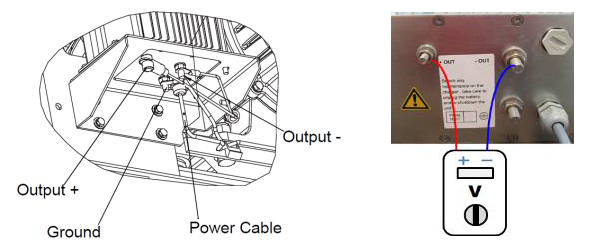
a.If there is voltage, proceed to step 7.
b.If there is no voltage, proceed to step 3.
Input Power Verification
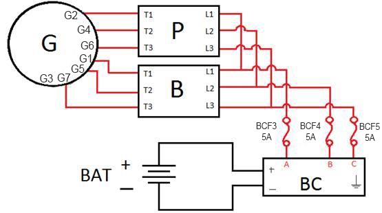
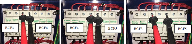
3.Measure the output voltage of the generator between the phases at the fuses BCF3, BCF4 & BCF5 in the receptacle box. The voltage must be within the range of 293-640 VAC. Refer to Figure.
Figure 2 - Generator Output Voltage
a.If the generator output voltage is out of specified range, refer to July 2017 TechLINE for generator troubleshooting.
b.If the generator output voltage is OK, then proceed to step 5.
c.If no voltage is found, check the line side of the fuse (BCF3, BCF4 & BCF5). If voltage is found on the line side but not the load side, the fuse is open.
d.If the fuse is open, turn the genset OFF. Check that there is no short circuit in the wiring between the fuse and charger. In case of short circuit, locate and repair. Remove and replace the fuse.
4.Power the genset on. If the input fuses blow immediately, the charger may have an internal short circuit. Proceed to step 5.
Verification (Resistance)
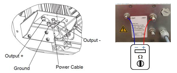
5.Turn genset off and isolate battery charger disconnecting power input and charger out +/- wiring.
6.Check for resistance between +OUT and –OUT on the battery charger. If resistance value is greater than 200Ω, the charger is good. If the resistance is less than 200Ω, the charger is defective and must be replaced. Refer to Figure.
Battery Check
7.Turn genset off and disconnect the battery from the charger, and check the charger output voltage (13.4 VDC – 13.9VDC).
8.If voltage is correct charger is working correctly, connect the battery to a battery tester and recharge or replace the battery, based on findings.
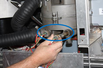
XtendFRESH™ Heater Checkout
There are two heaters within the XtendFRESH™ product that raise the temperature of the air going through the scrubber. The purpose of the heaters is to keep the scrubber bed dry in order to maintain efficiency. The two heaters are wired in series and are located inside the evaporator section on the XtendFRESH™ scrubber.
XtendFRESH Heater Circuit
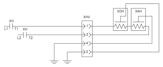
NOTE: the heaters are not accessible from the outside of the unit.
Heaters
To check the heaters, follow the below procedures.
Follow local Lockout Tagout guidelines when working on equipment.
1.With power off, check the heater resistance between XHT1 to XHT2 (450 to 500 ohms).
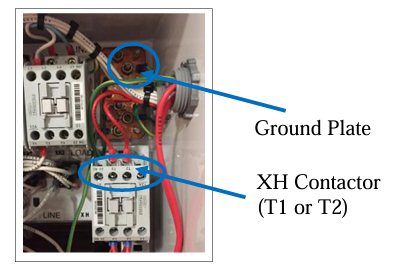
2.With the unit still off, check heater insulation resistance (megger test) from the load side of the XH contactor to plate ground in the XtendFRESH control box.
If greater than 1 Meg ohms to earth (plate ground), then no further test action required (heaters are ok). If heaters are less than 1 Meg Ohms to ground, then you will need to confirm which of the heaters is bad, by isolating them from inside the unit.
Check Heater Insulation Resistance
NaturaLINE® VFD Troubleshooting
The NaturaLINE® unit has a variable speed compressor controlled by a variable frequency drive inverter (VFD) and VFD interface module (VIM). If an Alarm 13 occurs, a fault is typically either in the module, or the inverter.
When Alarm 13 is active, the compressor contactor (CH) will be in the OFF state, and there is no communication between the Micro-Link™ 3 controller and the inverter. The following procedure will assist in identifying the correct component.
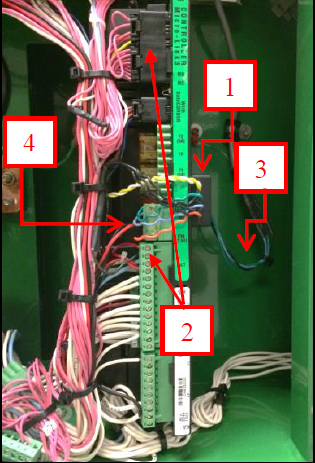
Step 1: Check LED on VIM (Figure 1, Location 1)
1.Turn off the unit.
2.Wait for 30 seconds and turn the unit back on.
3.After the display is turned on, the LED on the side of the VIM should blink long and short.
4.Watch the compressor contactor (CH). It will engage approximately 10 seconds after start up. If CH does not engage, troubleshoot the contactor.
5.A few seconds after the contactor is energized, inspect the LED on the side of the VIM and proceed to step 2 based on finding.
Step 2: Determine Action Based on Following 3 Conditions
•Condition 1: LED OFF (Figure 1, Location 2)
If the LED is off all the time, this means the VIM lost 5V or ground connection to the Micro-Link 3 controller.
Action: Check WHITE wire, which is 5V from Micro-Link 3 MB13 to the VIM; check BLACK wire from the VIM to the Micro-Link 3 KA13, which is the ground connection. Make sure both wires have good connection; there should be no loose connection or broken wire. Measure voltage to verify the 5VDC. If 5V is not present, replace the controller. If the 5 V is present, replace VIM module.
•Condition 2: LED Blinks Long-Short with CH Open (Figure 1, Location 3)
If you see quick blinking of the LED and then the compressor contactor opens and the LED reverts to long and short blinks, this means the Micro-Link 3 controller doesn’t receive a response from the VFD. The Micro-Link 3 controller will retry communication 3 times and if it does not receive a response from the VFD, it will raise alarm 13. At this point, the communication problem most likely happened between the VIM and the VFD.
Action: Check the BLUE, BLACK and GREEN wires on back side of the VIM. Make sure connections to the RED, BLACK and CLEAR shielded cables are good and secured. If wires are secured, proceed to step 3.
•Condition 3: LED Blinks Long-Short with CH Engaged (Figure 1, Location 4)
If the compressor contactor is closed and there is only long and short blinking, followed by the contactor opening, the communication problem most likely happened between the Micro-Link 3 and the VIM.
Action: Make sure the KH connector is seated properly, all wires are connected properly and screws are tight. If connection are secure, proceed to step 3.
Figure 1 Controller
Step 3: KH Connector
Refer to Figure 2. Turn off the unit. Disconnect KH connector and measure resistance from:
•KH6 (orange wire) to KA13 (ground connection)
•KH5 (blue wire) to KA13 (ground connection)
•KH1 (green wire) to KA13 (ground connection)
Figure 2 Resistance
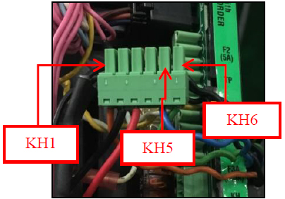
The reading should be 10K +/- 0.2K Ohm. An infinity reading suggests broken wire from KH connector to the VIM or a defective VIM. A near zero reading suggests short circuit of the wire or defective VIM. If readings are within the specified range, proceed to step 4.
Variable Frequency Drive Electrical Hazard. After disconnecting from power supply, wait seven (7) minutes before servicing to allow capacitors to completely discharge.
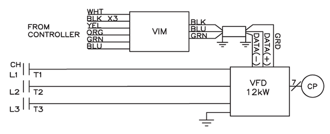
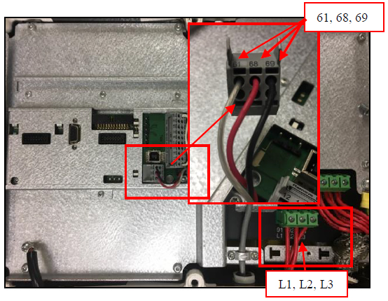
Step 4: Resistance Between 68 and 69
Find the 3-wire connector on the VFD with wire label 61, 68 and 69. Use a multi-meter to measure resistance between 68 and 69. Refer to Figure 3.
The resistance between 68 and 69 when the connector is disconnected, should be 115 to 125 Ohms. If your reading is infinity, it is most likely the connection from the connector to the VIM is open (check wiring). If you have low reading near 0, the VIM is short circuited. Replace VIM.
If ohm readings are correct, check power to the VFD, L1, L2, and L3. If power is present, replace the VFD.
Solenoid Valve Positioning
Recently we have had some field inquiries as to the normal positioning of the valves in each of our model units. In support of this request, the following is a short write up on the primary purpose of each valve, along with a table showing the normal position and part number required for each model unit
Unloader Solenoid Valve (USV), for EliteLINE unit only
•When opened, allows refrigeration system to operate in Unloaded Mode.
•When closed, allows refrigeration system to operate in Standard Mode
Economizer Solenoid Valve (ESV), for EliteLINE & PrimeLINE units
•When opened, allows refrigeration system to operate in Economized Mode.
•When closed, allows refrigeration system to operate in Standard Mode.
Oil Return Solenoid Valve (ORV), for 1st generation EliteLINE unit only
•Is normally open, the Oil Return Solenoid Valve opens periodically to drain the Oil Separator Tank back into the sump of the compressor.
Liquid Injection Solenoid Valve (LIV), for EliteLINE unit only
•Is normally open, the Liquid Injection Solenoid Valve opens periodically to quench (cool) the compressor, i.e. Dome Temperature control.
Expansion Bypass Solenoid Valve, for newer generation EliteLINE unit only
•When opened, it gives a small boost to cooling capacity, notwithstanding the current capacity mode.
Digital Unloader Valve (DUV), for PrimeLINE unit
•When opened, the compressor operates in a reduced cooling (unloaded mode).
•When closed, the compressor cooling operates in full cool mode (capacity is loaded).
Digital Loader Valve (DLV), for PrimeLINE unit with EDGE option only
•When opened, compressor cooling capacity is loaded (full cool).
•When closed, compressor cooling capacity is unloaded (partial cool).
| Valve | Position | Part | EliteLINE 531-001 to 399 551-001 to 399 |
EliteLINE 551-400 to 599 |
PrimeLINE 561-001 to 299 |
PrimeLINE 561-300 to 399 |
| USV | Normally Closed | Solenoid Coil | 14-01091-02 | 14-01091-02 | ||
|
|
Solenoid Valve | 14-01090-12 | 14-01090-12 | |||
| EXV | Normally Closed | Solenoid Coil | 14-01091-04 | 14-01091-04 | 14-01091-04 | 14-01091-04 |
|
|
Solenoid Valve | 14-01090-12 | 14-01090-12 | 14-01090-12 | 14-01090-12 | |
|
ORV |
Normally Opened | Solenoid Coil | 14-01091-04 | |||
| Solenoid Valve | 14-00285-00 | |||||
| LIV | Normally Opened | Solenoid Coil | 14-01091-04 | 14-01091-04 | ||
| Solenoid Valve | 14-00285-00 | 14-00285-00 | ||||
| XBSV | Normally Closed | Solenoid Coil | 14-01091-04 | |||
| Solenoid Valve | 14-01090-15 | |||||
| DUV | Normally Closed | Solenoid Coil | 14-00361-01 | 14-00361-02 | ||
| Solenoid Valve | 14-00361-00 | 14-00361-00 | ||||
| DLV | Normally Closed | Solenoid Coil | 14-00361-01 | |||
| Solenoid Valve | 14-00361-00 |
Global Training Schedule, 2018 Q1/Q2
Listed are the instructor-led training courses scheduled through June 2018. Classes are subject to a minimum requirement of 12 students. Courses marked with the asterisk are technician certification courses. The attendees the course need to pass both the hands on troubleshooting and written exam.
Approximately 30 days prior to the class start date, registered students will receive an email confirming the class is being conducted along with logistical information. You should not make travel arrangements to attend the class until after you have received the confirmation email.
|
Region |
Start Date |
Course Description |
Location |
|
APO |
1/16/2018 |
3-Day Container Technician * |
Yangon city, Myanmar |
|
APO |
2/14/2018 |
2-Day Container Technician * |
Christchurch, New Zealand |
|
APO |
2/27/2018 |
3-Day Container Technician * |
Suva, Fiji |
|
APO |
3/13/2018 |
3-Day Container Technician * |
Ho Chi Minh city, Vietnam |
|
APO |
3/19/2018 |
1-Week Container Technician * |
Mumbai, India |
|
APO |
3/28/2018 |
2-Day Gen Set Training |
Jakarta, Indonesia |
|
APO |
4/17/2018 |
3-Day Container Technician * |
Busan, South Korea |
|
APO |
4/18/2018 |
2-Day Container Technician * |
Sydney, Australia |
|
APO |
5/7/2018 |
1-Week Container Technician * |
Qingdao, China |
|
APO |
5/14/2018 |
1-Week Container Technician * |
Chennai, India |
|
APO |
6/20/2018 |
2-Day Container Technician * |
Perth, Australia |
|
EMEA |
1/11/2018 |
2-Day Container Technician * |
Port Louis, Mauritius |
|
EMEA |
1/15/2018 |
2-Day Container Technician * |
Mombasa, Kenya |
|
EMEA |
1/17/2018 |
2-Day Genset Course |
Mombasa, Kenya |
|
EMEA |
2/6/2018 |
3-Day Container Technician * |
Port Said, Egypt |
|
EMEA |
2/12/2018 |
2-Day Container Technician * |
Hamburg, Germany |
|
EMEA |
2/20/2018 |
2-Day Product Update Course |
Rotterdam, NL |
|
EMEA |
3/6/2018 |
2-Day Container Technician * |
Aarhus, Denmark |
|
EMEA |
3/13/2018 |
3-Day Container Technician * |
Barcelona, Spain |
|
EMEA |
3/20/2018 |
2-Day Container Technician * |
Dublin, Ireland |
|
EMEA |
3/27/2018 |
3-Day Container Technician * |
Porto, Portugal |
|
EMEA |
4/3/2018 |
3-Day Container Technician * |
St Petersburg, Russia |
|
EMEA |
4/17/2018 |
3-Day Advanced Container Update |
Haifa, Israel |
|
EMEA |
4/24/2018 |
3-Day Container Technician * |
Athens, Greece |
|
EMEA |
5/9/2018 |
2-Day Container Technician * |
Felixstowe, UK |
|
EMEA |
5/23/2018 |
2-Day Container Technician * |
Rotterdam, NL |
|
EMEA |
6/5/2018 |
3-Day Container Technician * |
Livorno, Italy |
|
EMEA |
6/12/2018 |
2-Day Container Technician * |
Gdynia, Poland |
|
LAO |
2/26/2018 |
1-Week Container Technician * |
Paranaguá, Brazil |
|
LAO |
3/5/2018 |
1-Week Container Technician * |
Pto Limon, CR |
|
LAO |
3/12/2018 |
2-Day Genset Course |
Panama City, Panama |
|
LAO |
3/13/2018 |
3-Day Container Technician * |
Panama City, Panama |
|
LAO |
4/17/2018 |
2-Day Genset Course |
Manzanillo, Mexico |
|
LAO |
5/7/2018 |
1-Week Container Technician * |
Santa Marta, Colombia |
|
LAO |
6/4/2018 |
3-Day Container Technician * |
Fortaleza, Brazil |
|
LAO |
6/7/2018 |
2-Day Genset Course |
Fortaleza, Brazil |
|
LAO |
6/11/2018 |
1-Week Container Technician * |
Puerto Barrios, Guatemala |
|
NAO |
1/15/2018 |
1-Week Container Technician * |
Miami, FL |
|
NAO |
1/15/2018 |
1-Week Container Technician * |
Houston, TX |
|
NAO |
2/12/2018 |
3-Day Container Technician * |
Elizabeth, NJ |
|
NAO |
2/14/2018 |
2-Day Genset Course |
Elizabeth, NJ |
|
NAO |
3/12/2018 |
1-Week Container Technician * |
Seattle, WA |
|
NAO |
3/19/2018 |
3-Day Container Technician * |
Norfolk, VA |
|
NAO |
3/22/2018 |
2-Day Genset |
Norfolk, VA |
|
NAO |
4/9/2018 |
3-Day Container Technician * |
Savannah, GA |
|
NAO |
4/12/2018 |
2-Day Genset Course |
Savannah, GA |
|
NAO |
5/14/2018 |
3-Day Container Technician * |
Oakland, CA |
|
NAO |
5/17/2018 |
2-Day Genset Course |
Oakland, CA |
Listed are the software release versions for operating and working with Carrier Transicold units. Prior to upgrading software on units, you should seek agreement from the equipment owners.
Recip (ML2i / 5159, ML3, 5167), Scroll (ML2i, 5360 / ML3, 5368)
Reciprocating Unit (ML2) - 1207, NaturaLINE (ML3, 5706)
Controlled Atmosphere - 3115
DataLINE 3.1 (Windows 10 compatible), DataBANK 0513.
Menu - 0116, Software cards with revision greater than 5159 or 5361 must have menu 0116 or an error could occur.
After completing a software upgrade, verify the user selections (i.e. defrost interval, set point, etc.).
TechLINE is a publication of Carrier Transicold.
Editor / Contributor: Perry Hoover
Contributors: Oh Boon San, Barry Hofsdal, David Whyte, Tom Graf, Matt Schlote
Thanks to all who supported this release.