November 2015 Issue
Inside This Issue:
FuelWise™ Power Saving Option
Carrier Transicold offers an energy-saving option called FuelWise™. The FuelWise™ option, a.k.a. Enhanced Economy Mode in the Operational and Service Manual, is an optimized software algorithm capable of delivering energy efficiency improvements for perishable cargoes transported by fleets not already using other types of energy management software, such as QUEST. It has been developed exclusively for PrimeLINE® units, PrimeLINE® units with EDGE technology and EliteLINE® systems with the Micro-Link® 3 controller installed.
FuelWise™ optimization software works during steady-state perishable cooling temperature control by dynamically cycling the refrigeration system on and off to save energy, while monitoring the rate of change in supply air fluctuation and integrating temperature control reference to set point. It then automatically determines when to provide cooling and when to cycle off the compressor, while still maintaining the supply air temperature within a predetermined range. In conjunction with cycling the refrigeration system on and off, the evaporator fans will cycle between high and low speeds to further optimize energy savings. The fans will run on low speed when the compressor is off and high speed when the compressor is on. In doing so, it reduces the cooling energy consumption while also reducing CO2 emissions related to that power consumption, while still maintaining temperature control within +/- 0.25 degrees Celsius from set point on an hourly average basis recorded by the Micro-Link Datacorder.
The FuelWise™ optimization software is model number configurable. If configured, it can be enabled or disabled by selecting code Cd63, pressing the arrow “UP” or “DOWN” keys to select “OFF” or “ON” and pressing “ENTER”. Also, depending on the customer request, model number is configured to either default “OFF” or “ON”. If the controller is configured with a default setting “ON,” it will reset the code select Cd63 option to “ON”, after every pre-trip or trip start. If default is set to “OFF”, the controller will reset code select Cd63 to “OFF” after pre-trip or trip start.
FuelWise™ optimization software is designed to engage in steady-state perishable cooling temperature control only.
Any intervention to the refrigeration system (e.g. Defrost termination, pre-trip termination, set point changed, power interruption, etc.) will suspend the engagement of FuelWise™ optimization software to the beginning of next Micro-Link Real-Time-Clock hour after the temperature in-range status is achieved again, during the current hour.
Regardless of FuelWise™ optimization software default setting, code Cd63 will turn off automatically upon:
Dehumidification function code Cd33 or Cd48, depending on model configuration changes from OFF to a valid relative humidity set point.
•ACT (automatic cold treatment) function code Cd51 changes from OFF to a valid setting
•ASC (automatic set point change) function code Cd53 changes from OFF to a valid setting
•QUEST (Cd50) is selected to “ON”
The operation of QUEST and FuelWise™ optimization software are mutually exclusive, and therefore cannot be offered together with the default setting “ON”. However, both options can be offered together when both have default settings of “OFF”.
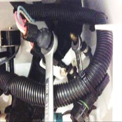
Interrogation Port Caps
On a recent voyage, one of Carrier’s service engineers noted that many container refrigeration units had the interrogation receptacle cover removed. The receptacle pins showed various degrees of corrosion caused by exposure to different elements. All of the units had tethered interrogation covers available, but only few were installed.

The corrosion on the pins can lead to several issues. First, corrosion can cause a poor connection of the pin to the interrogation port. This can lead to communication issues between the port and the controller while performing a service operation using DataLINE. It may take much longer to complete a download due to the multiple attempts the computer needs to retry getting the information. Second, where the corrosion is heavy, high humidity at contact points between pins and the battery can drain the battery capacity. This can be a concern when carrying cargo that requires battery backed recording, like USDA shipments.
In the near future, as technologies advance, more devices will communicate with the interrogation port. Corroded connections may interfere with these devices and prevent proper operation. Fastening the interrogation cap back in place during daily activities will help maintain a charged battery, and in the future, ensure proper communication between all devices on the container unit. A replacement cap and tether can be ordered from your local service center (part number 22-02413-00) if it is missing.
Pre-trip Using a GenSet “genPt”
A new optimized Genset pre-trip selectable option “gEnPt” was added to the NT ThinLINE pre-trip selection menu in SWR 5159. This selection should be made when running an Auto2 pretrip with genset PID numbers 2000 and greater.
![]()
The difference between the standard Auto2 and the “gEnPt” Auto2 is with the P8-1 test (Perishable Mode Pull Down Test).
For both standard Auto2 and the “gEnPt” Auto2, the system will run a normal P8-0. If the control temperature is below 15.6°C (60°F), the set point is changed to 15.6°C (60°F), and a 180 minute timer is started, raising the box temperature for the start of the pull down test (P8-1). If the control temperature is above 15.6°C (60°F) at the start of the test, then the test proceeds immediately to test P8-1 in the standard Auto2 pre-trip. In “gEnPt”, if the ambient temperature is above 25ºC (77°F), the condenser fan will run for 30 minutes, prior to initiating P8-1.
There are no changes to any of the current Auto pre-trip options. Genset pre-trip is an additional feature.
PrimeLINE Pressure Transducer
Both the EPT and SPT pressure transducers are attached to the suction line using schrader fittings. When replacing a transducer, it is important to remove it from the schrader connection using both a 7/16” and a 5/8” wrench.
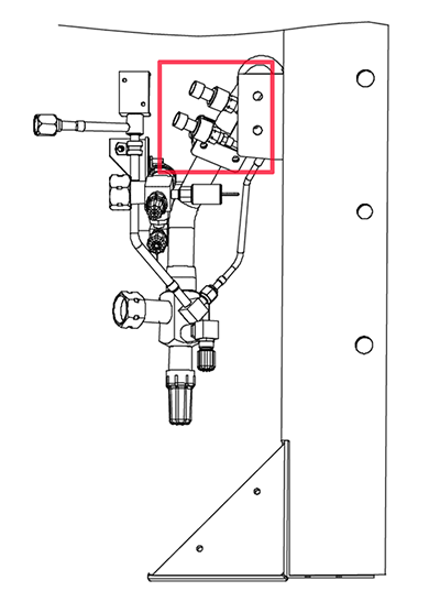
The 7/16” wrench will hold the schrader fitting in place while counter rotating the transducer fitting using the 5/8” wrench.
Failure to hold the schrader fitting may cause the feeder line to twist the schrader port, requiring a change of the complete fitting. Perform the same method of retaining the schrader fitting during the install. It is recommended that after you reinstall the fitting that you leak check the connection.
NT Start Logic (Software Version 5165)
With software version 5165, the Carrier ThinLINE® unit has a new start algorithm when operating under genset power. This algorithm looks at the incoming voltage, the ambient temperature and the amount off time since the last power cycle to determine if the start algorithm is required. Depending on these inputs, the unit may first go into a startup defrost mode. Upon completion of the startup defrost, the unit will resume to normal control.
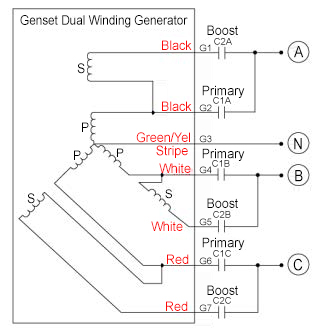
Tier 4 Genset (50Hz / 60Hz)
The Tier 4i single speed genset starts and runs at 60 Hz. The Tier 4i dual speed genset starts at 60 Hz and then automatically goes to 50 Hz after 2 hours and stays there for the balance of the trip. In contrast, the Tier 4 genset has a permanent magnet dual winding generator that starts at 50 Hz. The voltage output is controlled by a programmable “voltage and dual-speed controller” that energizes primary or boost contactors based on the power demands on the genset. As the container becomes loaded, voltage drops and current increases, and the genset will switch windings or speed based on power demand and ambient conditions.
Upon starting up of the generator, the unit will run at 50 Hz in the boost circuit for up to the first 5 minutes and 30 seconds, energizing the boost contactor. Once the unit is running, the controller will read the voltage output of the generator and adjust by remaining in the boost circuit mode or switching to the primary circuit mode.
Either output (primary or boost) can be at 50 Hz (1500 rpm) or 60 Hz (1800 rpm). The speed change to 1800 rpm will occur when the voltage drops to 360V steady state, which typically occurs when the ambient temperature is high and the unit is heavily loaded. The unit will typically run at 50 Hz to reduce fuel consumption and will vary generator output via winding selection.
There is no voltage regulator, the operation is in either of the two speeds with either the primary or the boost winding engaged.
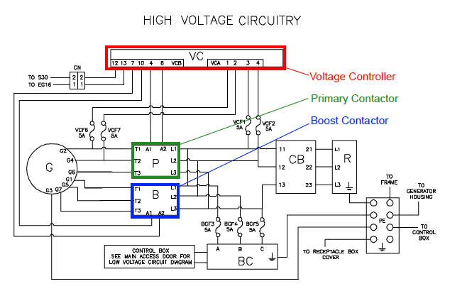
As stated above, the voltage controller is a programmable module that can be upgraded via Carrier-provided software. The latest software revision is 1.0.53. To ensure your control module has the latest software revision, you can check the part number on the module (p/n should be 12-00707-03 with SW Rev 1.0.53) or a previous part number with a green dot indicating that it was updated in the field.
If you need to update the voltage controller, contact your regional service engineering manager for direction.
ML3 Controller Field Software
During installation of software 5159.ml3 or 5361.ml3 (or greater) in an Micro-Link 3 controller (with yellow or green labels), if the software card is removed, or the wrong menu file is installed on the card (<116), or the unit is powered down during the boot loading process of the upload, the controller may become unresponsive for several minutes after the power is turned on, or possibly an Err#2 Alarm will occur.
If either occurs, the following steps should be taken prior to changing out the controller.
1.Confirm the software card is good. It is recommended that the card be installed into another unit. If “bad card” is displayed, replace the card.
2.Re-install the programming card and try reloading software.
If the controller still fails to respond and the programming card is determined to be ok, access the Carrier Transicold Transcentral web site and download the appropriate field version software along with instructions on how to use the software.
•“recp51XX_ml3_btldr00YY_field.1024” (for ThinLINE unit)
•“scrl53XX_ml3_btldr00YY_field.1024” (for EliteLINE/ PrimeLINE units)
If you do not have access to Transcentral, contact your regional service engineering manager.
It is important to follow the steps exactly as outlined in the instructions downloaded from the website when using this software. The procedure uses a special software file installed on a PCMCIA card via Card Manager in conjunction with a hardware jumper prior to the installation of the configuration and operational software.
On completion of the software loading, install a new software card with the latest software revision for the appropriate unit.
When installing software into a unit, it is important NOT to remove the programming card or interrupt the programming process until "Pro donE" is displayed.
If the controller does not respond after taking these actions, it should be replaced.
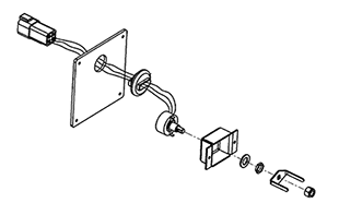
Upper VPS / Repair Kit
During setup of the Vent Positioning Sensor (VPS), the user is allowed 5 minutes to make necessary adjustments to the vent setting. After the five minute adjustment time, the controller monitors the panel for stability (no movement). The controller sends a 5 VDC signal to the VPS to determine the vent position, which is recorded in the DataCorder™. A position change is recorded if a manual change of 5 cmh or greater is sensed and remains in this position for 4 minutes.
If alarm #50 occurs, the sensor is indicating that the setting position has not remained stable after the five minute time allowed for the setting. This could occur if the thumb screw is left loose allowing the position of the vent to change while in transit.
To Check the Sensor:
1.Power the unit OFF.
2.Ensure that the thumb screw on the front of the panel is tight.
3.Turn the unit ON and wait for 5 minutes.
4.If the alarm reappears, the sensor should be replaced.
The sensor can be replaced by either ordering a complete panel assembly, 79-01902-xx (see parts manual), or by replacing the individual sensor with kit # 76-66615-00. Kit includes a sensor, an adapter and full instructions. See TechLINE July 2003.
The following manuals were added to the Mobile Manual Link since the June 2015 TechLINE announcement:
T362 - PrimeLINE: 69NT40-561-200 to 299
T363 - ThinLine: 69NT40-541-500 to 599
T368 - ThinLine Up flow: 69NT40-541-505, 508, 509
Listed below are the instructor-led training courses scheduled through Q2 2016. Courses are subjected to a minimum requirement of 12 students.
Approximately 30 days prior to the class start date, registered students will receive an email confirming the class is being conducted along with logistical information. You should not make travel arrangements to attend the class until after you have received a confirmation email.
|
Region |
Start Date |
Course Description |
Location |
|
APO |
2/16/2016 |
3-Day Advanced Container Update |
Suva, Fiji |
|
APO |
3/14/2016 |
3-Day Advanced Container Update |
Tauranga, NZ |
|
APO |
4/4/2016 |
3-Day Basic Container Update |
Lae, Papua New Guinea |
|
APO |
5/9/2016 |
1-Week Container Basic |
Qingdao, China |
|
APO |
5/17/2016 |
3-Day Advanced Container Update |
Ho Chi Minh City, Vietnam |
|
EMEA |
2/9/2016 |
2-Day Container Product Update |
Hamburg, Germany |
|
EMEA |
2/9/2016 |
2-Day Container Product Update |
Port Louis, Mauritius |
|
EMEA |
3/8/2016 |
2-Day Container Product Update |
Rotterdam, NL |
|
EMEA |
3/14/2016 |
3-Day Advanced Container Update |
Gioia Tauro, Italy |
|
EMEA |
3/16/2016 |
2-Day Container Product Update |
Le Harve, France |
|
EMEA |
3/17/2016 |
2-Day Container Product Update |
Tauranga, NZ |
|
EMEA |
4/13/2016 |
2-Day Container Product Update |
Dubai, UAE |
|
EMEA |
4/20/2016 |
2-Day Container Product Update |
Turkey |
|
EMEA |
5/10/2016 |
2-Day Container Product Update |
Felixstowe, U.K |
|
EMEA |
5/17/2016 |
3-Day Advanced Container Update |
Vigo, Spain |
|
LAO |
1/11/2016 |
1-Week Container Basic |
Turbo, Colombia |
|
LAO |
2/15/2016 |
1-Week Container Basic |
Buenos Aires, Argentina |
|
LAO |
2/22/2016 |
1-Week Container Basic |
Itajaí, Brazil |
|
LAO |
3/7/2016 |
1-Week Container Basic |
Panama |
|
LAO |
5/9/2016 |
1-Week Container Basic |
Paita, Peru |
|
LAO |
5/16/2016 |
3-Day Advanced Container Update |
Santos, Brazil |
|
LAO |
5/19/2016 |
2-Day Gen Set |
Santos, Brazil |
|
LAO |
6/6/2016 |
1-Week Container Basic |
Guayaquil, Ecuador |
|
LAO |
6/11/2016 |
2-Day Gen Set |
Fortaleza, Brazil |
|
LAO |
6/29/2016 |
2-Day Gen Set |
Salvador, Brazil |
|
NAO |
2/8/2016 |
1-Week Container Basic |
Los Angeles CA |
|
NAO |
2/15/2016 |
2-Day Gen Set |
Seattle, WA |
|
NAO |
2/17/2016 |
3-Day Advanced Container Update |
Seattle, WA |
|
NAO |
4/4/2016 |
3-Day Advanced Container Update |
Savannah, GA |
|
NAO |
4/7/2016 |
2-Day Gen Set |
Savannah, GA |
|
NAO |
5/16/2016 |
3-Day Advanced Container Update |
Houston, TX |
Software Release Update
Listed are the software release versions for operating and working with Carrier Transicold units. Prior to upgrading software on units, you should seek agreement from the equipment owners.
Recip (ML2i / 5159, ML3, 5165), Scroll (ML2i, 5360 / ML3, 5365)
Reciprocating Unit (ML2) – 1207
Controlled Atmosphere – 3115
DataLINE 2.2 / DataBANK 0513.
Menu – 0116, Software cards with revision greater than 5159 or 5361 must have menu 0116 or an error could occur.
After completing a software upgrade, verify the user selections (i.e. defrost, set point, etc.).
TechLINE is a publication of Carrier Transicold.
Editor / Contributor: Perry Hoover
Contributors: Oh Boon San, Barry Hofsdal, Mark Donahoe, Nadir Guenane
Thanks to all who supported this release.