
June 2015
In November of 2014, Carrier Transicold launched a new web portal which allows access to a new kind of manual that is easily viewed on mobile devices such as a smart phone or tablet. The first mobile manuals available were the T365 PrimeLINE with EDGE Technology and T349 NaturaLINE. Since then, the mobile manual library has grown to ten and includes ThinLINE (T363 and T368), XtendFRESH (T366), and the Genset Tier 4i (T343 and T345) and Tier 4 product lines (T360 and T361).
Mobile manuals allow Technical Publications to provide benefits to the end user that the traditional PDF versions cannot. Benefits include quicker download speeds, as the pages are more lightweight than the PDF version, embedding of high quality drawings and schematics, and displaying multimedia such as videos and animations. These benefits and others go a long way towards improving the quality of the technical manuals and helping the technicians to troubleshoot the units. Since its launch, we have observed an increased flow of visitors to the Mobile Manual site with the T365 PrimeLINE with EDGE Technology leading the way.
From the November 2014 introduction through mid-June, there have been over 2,275 users visiting the manual, with just under 10,000 page views. Since April alone, there have been 1,530 users viewing approximately 5,000 pages of technical information.
With these numbers, we see an increase in usage and we expect this trend to continue as more mobile manuals are made available to the public.
In addition to the mobile manuals, we have launched a Technicians Toolbox which includes the Carrier Transicold Alarm web application, along with other web applications such as reference tables and conversion tools.
With the success of the mobile application, Carrier Transicold plans to continue to build on the Toolbox and welcomes recommendations from the field for new tools to be added, which will aid in the troubleshooting process of the units. Recommendations for additional tool applications can be provided to your regional Carrier Transicold Service Manager.
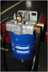
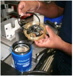
As of August 2014 production, Carrier Transicold Container has implemented a change to the 90 degree fuel filter return fitting on top of the fuel filter on both UG and RG Genset units going from a reduced flow to a full flow fitting. This change will reduce the pressure in the filter, reducing the sensitivity to the torque requirement on the filter (18ft / lbs, 2.5 m-Kg). The fitting (P/N 74-00318-00) can be added to any RG or UG genset in the field.
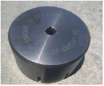
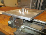
In parallel to this, we have developed a tool to be used when replacing the fuel filter. This tool (P/N 07-00537-00) will help ensure that the fuel filter bowl is torqued appropriately. The torque tool assembly includes a black socket (P/N 07-00537-11) and torque base (P/N 07-00537-02).
Following is an overview of the instructions to install the fitting and use the new tool.
Be sure power is turned off and the negative battery cable is disconnected before working on the generator set.
Instructions for Replacing the Fuel Fitting Kit (P/N 74-00318-00)
1.Remove cover from Genset unit.
2.Drain a few ounces of fuel from filter by turning the black bleed port (drain valve) counter clockwise.
3.Remove hose clamp and discard.
4.Remove hose from fitting.
5.Remove brass fitting (with orifice) and discard.
6.Add Teflon pipe sealant to the new fitting (without orifice).
7.Install the new fitting into the fuel filter head (position fitting to the side of the head assembly).
8.Mark top of new fitting with white marker/paint pen to show fitting has been changed.
9.Inspect hose, if compromised cut off small section.
10.Reinstall hose and install new clamp.
11.Reinstall cover.
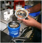
Instructions for Replacing the Fuel Filter using the Torque Tool Assembly
1.Bleed the fuel from the filter bowl assembly by turning the black bleed port (drain valve) counter clockwise 2 turns. Loosen the filter element to provide faster flow.
2.Close the bleed port (drain valve) once the bowl is empty.
3.Remove filter element/bowl assembly from the unit using a strap wrench.
4.Drain any excess fuel from the filter.
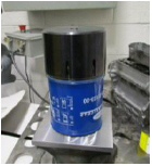
5.Secure tool base (P/N 07-00537-02) and element in a table vise and remove plastic bowl using the black socket tool (P/N 07-00537-11).
6.Discard used black bevel cut gasket or used blue O-ring, and lubricate the new filter bowl O-ring provided in the kit using clean diesel fuel.
7.Insert the lubricated blue O-ring gasket into the bowl’s O-ring gland/slot.
8.Coat black threads of filter element with clean diesel fuel.
9.Reinstall the clear bowl until first contact with blue O-ring and filter element.
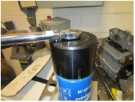
10.Using black socket (P/N 07-00537-11) with torque wrench, torque to 18ft/lbs. / 2.5 m-Kg.
11.Lubricate the black element square cut gasket using clean diesel fuel.
12.Fill element with clean fuel.
13.Reinstall filter element/bowl assembly to the metallic filter head assembly.
14.Using a strap wrench, tighten assembly ~¾ turn after gasket touches the filter head assembly
Over the years Carrier Transicold has published many TechLINE articles. To assist in your continued utilization of the information, we have categorized and listed the articles alphabetically below.
Each of these articles can be found by going to the Carrier Transicold container web site at www.container.carrier.com, select Service and Support / TechLINE and scroll down to the desired article date.
Contents for Container:
Topic |
Newsletter |
|---|---|
Articles of Introduction |
|
ACT |
3rd 2007 |
Analyzer |
4th 2003 |
ASC |
3rd 2007 |
Anti-Tamper System |
2nd 2014 |
DataBank |
4th 2004 |
Dual Temp Unit |
3rd 2006 |
DataCorder Storage |
4th 2009 |
Defrost Pulsing Logic |
3rd 2010 |
e-Autofresh |
1st 2008 |
eAutoFresh CO2 Sensor Zero |
1st 2009 |
EBS |
2nd 2003 |
EliteLINE (HARP Stepper adaptor) |
1st 2006 |
EliteLINE |
4th 2001 |
LED Display |
4th 2003 |
LVPS |
1st 2004 |
Mobile Manuals |
4th 2014 |
ML3 |
1st 2004 |
ML3 Green Label Controller |
4th 2014 |
ML3 Old Controller Message |
4th 2014 |
NatureFRESH |
2nd 2002 |
NaturaLINE Introduction |
2nd 2013 |
PC card adapter |
3rd 2005 |
PrimeLINE |
3rd 2007 |
PrimeLINE Diagnostics & Update |
3rd 2010 |
PrimeLINE Controller manual bypass |
3rd 2011 |
PrimeLINE Pressure Transducer Test |
3rd 2012 |
PrimeLINE 561-200 New Look |
2nd 2013 |
Quest |
1st 2008 |
Real Time Clock Battery Replace |
4th 2010 |
ThinLine (HARP) |
3rd 2005 |
ThinLine 541-5xx New Look |
2nd 2013 |
USDA and Cargo Probes |
1st 2009 |
UVPS Repair |
3rd 2011 |
UVPS Setting |
4th 2014 |
VPS |
2nd 2003 |
XtendFRESH Introduction |
4th 2013 |
XtendFRESH Container Leak check |
4th 2014 |
XtendFRESH PreTrip |
4th 2014 |
XtendFRESH Prior to Servicing |
4th 2014 |
Alarms, Codes & Auto PTI |
|
AL#06 Enhancement |
3rd 2008 |
AL#15 LOC |
4th 2004 |
AL#24 Scroll Comp IP |
4th 2012 |
AL#50 VPS |
2nd 2003 |
AL#53 Battery Pack (deactivate) |
3rd 2007 |
AL#62 XtendFRESH O2 out of range |
4th 2014 |
AL#72 Out of Range |
4th 2010 |
Alarm App |
2nd 2014 |
All alarms defined to date |
1st 2009 |
All alarms defined to date |
3rd 2005 |
ERR1 Diagnostics |
2nd 2013 |
Humidity Sensor, DPT, EEV Diagnoses |
2nd 2014 |
dAL86 & 87 RTC Battery Diagnostics |
3rd 2012 |
CD#16 Unit Run time comp reset |
3rd 2008 |
CD#27 (auto defrost added) |
1st 2004 |
CD#43,44,45 conf var reassignment |
1st 2004 |
CD#45 LVPS calibration |
1st 2005 |
CD#49 (# of Days to last PT) |
4th 2004 |
CD#59 PL Pump Down |
4th 2011 |
P#5-10,11,12 |
1st 2008 |
P#6-5 Compressor Leak Test |
4th 2013 |
P#6-6 EL Valve Diagnostics |
4th 2009 |
P#6-7 PL DUV/DLV Diagnostics |
2nd 2014 |
Compressors |
|
Oil check Procedure |
3rd 2005 |
ThinLine Sight Glass Elimination |
3rd 2010 |
ThinLine (Icing) |
1st 2004 |
Scroll part # history |
3rd 2006 |
Scroll ROC |
3rd 2005 |
Scroll Start up Logic |
2nd 2003 |
Scroll (Trouble Shoot) |
4th 2004 |
Contactors |
|
Pozi-drive |
3rd 2006 |
Replacement |
2nd 2002 |
Heaters |
|
Heater Meg ohm Reading |
2nd 2014 |
Motors |
|
3 Phase Motors |
3rd 2006 |
Condenser Motor PL EDGE Limp Home |
4th 2014 |
Evaporator Evaluation |
3rd 2006 |
Evaporator plug adapter |
4th 2003 |
Evaporator Motor Adapter & workaround |
4th 2013 |
Evaporator fan blades (removal) |
2nd 2003 |
Evaporator Section Cleaning |
4th 2010 |
Motor Diagnostics |
4th 2010 |
Refrigeration |
|
CareMAX Introduction |
2nd 2014 |
Condenser Coil (coil 3/8 vs 7mm) |
4th 2004 |
CO2 Refrigerant |
3rd 2012 |
DPRV test procedure |
1st 2005 |
DPRV Elimination |
3rd 2010 |
DPRV ML3/5147 kit |
4th 2010 |
Evacuation & Dehydration |
4th 2011 |
ESV check |
1st 2004 |
Electronic Expansion Valve TS |
1st 2009 |
HPS Enhancement |
1st 2004 |
LIV PrimeLINE |
3rd 2008 |
Refrigerant Quality |
3rd 2012 |
WCC Sight Glass Replacement |
3rd 2012 |
Software |
|
Bootloader Software Updating |
4th 2014 |
DataLine (Acronyms) |
3rd 2008 |
DataLine (Omni drive vs Vista) |
3rd 2008 |
DataBANK & Cold treatment |
3rd 2012 |
ID (Program from keypad) |
1st 2008 |
LED (Controller status) |
3rd 2007 |
PCMCIA cards (Format) |
4th 2004 |
Pretrip Startup |
1st 2008 |
Probe Check Logic |
3rd 2008 |
RTC (Program from keypad) |
1st 2008 |
Unit startup (Id, software version) |
3rd 2007 |
Contents for Controlled Atmosphere:
Topic |
Newsletter |
|---|---|
CA controller Programing |
3rd 2012 |
CO2 sensor (Trouble Shoot) |
3rd 2005 |
Spare Parts |
2nd 2002 |
Contents for Genset:
Topic |
Newsletter |
|---|---|
Annual Inspection |
4th 2004 |
Battery Charger Diagnostics |
4th 2012 |
Biodiesel fuels |
3rd 2006 |
Dual Speed |
3rd 2008 |
Dual Speed kit |
4th 2010 |
Engine Serial # |
3rd 2005 |
Generator (Bearing O-ring) |
1st 2002 |
Low Coolant Sensor |
3rd 2007 |
Oil filter selection |
1st 2004 |
Oil filter (Extended Life) |
4th 2003 |
Oil Filter Positioning |
2nd 2003 |
Poly V-belt |
1st 2006 |
Startup |
3rd 2011 |
Tier 4 PowerLine Introduction |
4th 2013 |
Tier 4 Voltage Control Diagnostics |
2nd 2014 |
Tier 4i Engine |
1st 2008 |
Tier 4i Engine Module Diagnostics |
3rd 2010 |
Tier 4i Engine Speed |
4th 2009 |
Contents for Transcentral:
Topic |
Newsletter |
|---|---|
Container Matrix |
4th 2011 |
Warranty History |
1st 2006 |
Warranty Lookup |
1st 2004 |
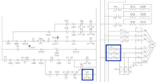
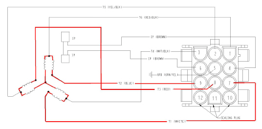
PrimeLINE with EDGE Dual Speed Condenser Motor CTD# 54-00670-20
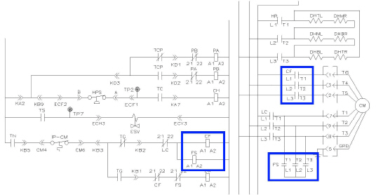
The PrimeLINE EDGE model unit uses a three phase, dual speed (High / Low) condenser motor with two sets of Y motor windings. To control the motor in high speed the windings are electrically connected and energized in parallel using the CF and FS Contactors. For Low speed operation the motor windings are energized in series using the LC Contactor.
•CF - Condenser Fan Contactor (High Speed)
•FS - Condenser Fan Contactor (High Speed Shorting)
•LC - Condenser Fan Contactor (Low Speed)
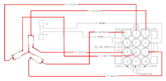
Condenser Motor (Low Speed)
Contactor LC shall energize. When LC Contactor is energized, LC Contactor T1, T2, T3 delivers three phase power to Condenser Motor Electrical Connector Pin7, Pin9, Pin8 respectively. Condenser Motor Electrical Connector Pin7, Pin9, Pin8 then delivers three phase power to Condenser Motor Winding T1, T2, T3 respectively.
When the LC Contactor is energized, three phase power is delivered to the two sets of Y Motor Winding connected in series.
Motor winding in series has higher impedance, therefore leads to lower power consumption, i.e. Low Speed application.
Condenser Motor (Low Speed)
CH Contactor Energized
Condenser Motor (High Speed) - Both
Contactor CF and FS shall energize. When CF energizes, CF Contactor T1, T2, T3 delivers three phase power to Condenser Motor Electrical Connector Pin1, Pin3, Pin2 respectively. Condenser Motor Electrical Connector Pin1, Pin3, Pin2 then delivers three phase power to Condenser Motor Winding T6, T4, T5 respectively. Three phase power is delivered to one set of the Motor Winding (Y connection).
When FS is energized, FS Contactor L1, L2, L3 creates a “jumper” circuit to Condenser Motor Winding T1, T2, T3 respectively, three phase power (from Electrical Connector Pin1, Pin3, Pin2) is delivered to the second sets of Motor Winding (T6,T4,T5).
With the CF and FS Contactors energized, three phase power is delivered to two sets of Y Motor Winding connected in parallel.
Motor winding in parallel has lower impedance, therefore leads to higher power consumption, i.e. High Speed application.
Condenser Motor (High Speed)
CF and FS Contactors Energized
Condenser Motor Essential Notes
The LC Contactor is electrically interlocked against CF and FS Contactor. This will prevent the CF and FS contactor to engage with the LC is energized, as this would otherwise cause an electrical failure and malfunction.
TECHLINE (November 2014 Issue) contains information on “Condenser Motor Limp Home”, a procedure written to aid installation of a Three Phase Single Speed Condenser Motor into a 69NT40-561-3XX (PrimeLINE with EDGE) unit with a dual speed motor as an emergency when a direct replacement is not readily available.
Listed below are the instructor-led training courses scheduled through Q4 2015. Courses are subjected to a minimum requirement of 12 students.
Approximately 30 days prior to the class start date, registered students will receive an email confirming the class is being conducted along with logistical information. You should not make travel arrangements to attend the class until after you have received a confirmation email.
Region |
Start Date |
Course Description |
Location |
APO |
9/16/2015 |
2 Day Container Product Update |
Jakarta, Indonesia |
APO |
9/24/2015 |
2 Day Container Product Update |
Pusan, Korea |
APO |
10/20/2015 |
3 Day Advanced Container Update |
Christchurch, New Zealand |
APO |
11/17/2015 |
3 Day Advanced Container Update |
Lae, Papua New Guinea |
APO |
11/18/2015 |
2 Day Container Product Update |
Kobe, Japan |
APO |
11/23/2015 |
3 Day Advanced Container Update |
Davao, Philippines |
APO |
11/26/2015 |
2 Day Gen Set |
Davao, Philippines |
EMEA |
9/1/2015 |
2 Day Container Product Update |
Hamburg, Germany |
EMEA |
9/7/2015 |
1 Week Container Basics |
Durban, South Africa |
EMEA |
9/9/2015 |
2 Day Container Product Update |
Bremerhaven, Germany |
EMEA |
9/15/2015 |
2 Day Container Product Update |
Antwerp, Belgium |
EMEA |
9/15/2015 |
2 Day Container Product Update |
Cape Town, South Africa |
EMEA |
10/6/2015 |
2 Day Container Product Update |
Gdynia, Poland |
EMEA |
10/13/2015 |
2 Day Container Product Update |
Valencia, Spain |
EMEA |
11/16/2015 |
1 Week Container Basics |
Luanda, Angola |
EMEA |
11/18/2015 |
2 Day Container Product Update |
Mombasa, Kenya |
EMEA |
11/25/2015 |
2 Day Container Product Update |
West Africa |
LAO |
7/27/2015 |
1 Week Container Basics |
San Jose, Costa Rica |
LAO |
8/10/2015 |
3 Day Advanced Container Update |
Santos, Brazil |
LAO |
8/13/2015 |
2 Day Gen Set |
Santos, Brazil |
LAO |
8/25/2015 |
2 Day Gen Set |
Puerto Barrios, Guatemala |
LAO |
9/7/2015 |
2 Day Gen Set |
Lima, Peru |
LAO |
9/10/2015 |
2 Day Gen Set |
Guayaquil, Ecuador |
LAO |
10/15/2015 |
1 Week Container Basics |
Veracruz, Mexico |
LAO |
10/26/2015 |
1 Week Container Basics |
Puerto Cortes, Honduras |
LAO |
11/09/2015 |
1 Week Container Basics |
Asuncion, Paraguay |
NAO |
8/17/2015 |
3 Day Advanced Container Update |
Miami, FL |
NAO |
8/20/2015 |
2 Day Gen Set |
Miami, FL |
NAO |
9/14/2015 |
3 Day Advanced Container Update |
Toronto, Canada |
NAO |
9/21/2015 |
3 Day Advanced Container Update |
Oakland, CA |
NAO |
9/24/2015 |
2 Day Gen Set |
Oakland, CA |
NAO |
11/2/2015 |
1 Week Container Basics |
Elizabeth, NJ |
In ongoing efforts to improve the reliability of our products, parts that fail under warranty are inspected for root cause of failure; these inspections, form the basis for continuous improvements to our products. The MPR process is the essential foundation of this ongoing process.
All parts changed under warranty should have an MPR tag attached and the part held on site for 120 days. During warranty claim submittal you will be advised if a part has to be returned under this MPR process. Unless separately advised, Part Shipping locations are:
•North America (USA and Canada) - Return to Syracuse TR20, attention Service Engineering.
•EMEA Region - Return to Carrier Transicold, Rotterdam
•All other countries - Parts should be returned to the Parts warehouse from where the part was purchased
Listed are the software release versions for operating and working with Carrier Transicold units. Prior to upgrading software on units, you should seek agreement from the equipment owners.
Recip (ML2i / ML3, 5159), Scroll (ML2i, 5360 / ML3, 5365)
Reciprocating Unit (ML2) – 1207
Controlled Atmosphere – 3115
DataLINE 2.2 / DataBANK 0513.
Menu – 0116, Software cards with revision greater than 5159 or 5361 must have menu 0116 or an error could occur.
After completing a software upgrade, verify the user selections (i.e. defrost, set point, etc.).
TechLINE is a publication of Carrier Transicold.
Editor / Contributor: Perry Hoover
Contributors: Christine Bocyck, Barry Hofsdal, Mark Donahoe, Nadir Guenane, Tom Graf
Thanks to all who supported this release.