December 2011 Issue
Inside This Issue:
Container Product Matrix
As part of Carrier Transicold’s continued commitment to customer satisfaction, we have updated the online version of the Container Products Matrix T-300 manual. It can be accessed from Carrier Transicold"s TransCentral™ Web site at https://www.transcentral.carrier.com.
The Container Products Matrix provides a high level overview of the units features. Unit information can be found by searching for the Parts Identification Number (PID), ex. NT-1212 or the model number, ex. 69NT40-541-305. PID, model, as well as serial numbers can be found on every unit.s serial plate located on the back wall of the condenser section. On the scroll unit it is to the left of the receiver or water cooled condenser. On the reciprocating units, it is to the left of the compressor.
While, the model number identifies the overall unit configuration, it is recommended that the PID number be used to search the Container Products Matrix as it provides unit-specific information, including installed options, factory provisioned options (that allow for field installation of optional equipment), and any parts that may have been customized for that unit. Referencing the PID is the best way to make sure that your search identifies the parts specific to each individual unit.
Once the PID is selected from the drop down menu, the model option will be displayed. By selecting and clicking on the PID or model number, a listing of the specific options for the unit selected will display. By selecting and clicking on each specific option, the user can see the legend for each option.
This Products Matrix ensures that you can easily identify the correct information on the unit that you are working on.
Refrigeration System Evacuation and Dehydration
After performing refrigeration service work on a unit, it is necessary to evacuate and dehydrate the unit to ensure long term operational performance and reliability.
Failure to perform a proper evacuation may result in moisture being left in the system. The existence of moisture in a refrigeration system is one of the leading causes of trouble and poor performance. The presence of moisture results in multiple problems and it is good to understand these to better recognize why it is necessary to ensure a proper evacuation is completed. To start, moisture mixing with the refrigerant oil reduces the oils lubricating ability which results in compressor cylinder wear. Moisture mixing with refrigerant can also cause the formation of acids. These acids then attack almost all of the materials that they come in contact with (brass, copper, steel, etc.) and this reaction creates a solid detachable product called “sludge.” This sludge, then travels throughout the system eventually clinging to the internal components, which not only blocks refrigerant from flowing, but also results in further corrosion of the parts as the sludge usually contains acid. And finally, moisture alone can result in freeze-ups with the creation of ice crystals forming at the expansion valve, causing blockage of refrigerant flow and loss of cooling.
With an understanding of these risks it is recommended that the service technician take the best possible actions to ensure contaminants are removed from the system.
Tools:
Proper evacuation begins with a well-maintained vacuum pump. A vacuum pump must be a two-stage pump and have a rated capacity of three to six cubic feet per minute (CFM). A pump of this capacity is available from Carrier Transicold Performance Parts, part number 07-00176-11. The oil used in the pump will trap some of the moisture that is removed from the refrigeration system. Moisture trapped in the oil reduces the vacuum pump efficiency, as the oil is the sealing medium. If left in the pump for extended periods this moisture may also cause damage to the seals and metal surfaces of the pump. To keep a vacuum pump in top condition, closely adhere to the manufacturer's maintenance recommendations. At minimum, every three times a vacuum pump is used, the oil must be changed. Use only vacuum pump oil in vacuum pumps.
To ensure a proper and fast evacuation of the system; use large diameter, short evacuation hoses for all connections during evacuation. Evacuation hoses are designed especially for this purpose and are available from refrigeration suppliers. The standard manifold gauge set is not recommended for evacuation, as the internal body porting is too small for good flow at low pressures. A large manifold gauge set made for evacuation can be used or a vacuum manifold can be attached directly to the vacuum pump as shown in Figure 1.
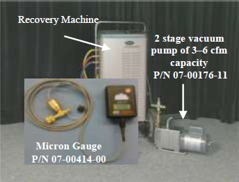
The only way to ensure that a good evacuation has been achieved is through the use of a micron gauge (electronic vacuum gauge). A micron gauge measures the extremely low absolute pressures that are necessary for removal of moisture from the system. Use of this gauge is essential in determining the quality of the vacuum. Five hundred microns, a measurement used in evacuation, is approximately 1/50th of an inch of mercury. This is difficult to read on a standard compound suction pressure gauge and, as such, a standard manifold gauge set is not recommended.
A micron gauge is available from Carrier Transicold Performance Parts, part number 07- 00414-00.
Two evacuation methods are recommended by Carrier Transicold for service on Carrier equipment depending on the extent of the repair.
Evacuation Procedure #1 should be performed after a major system repair (ex. compressor, evaporator, or condenser replacement). After a minor system repair, (ex. replacement of a solenoid valve or the filter drier) perform Evacuation Procedure #2.
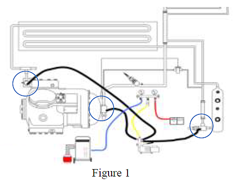
Evacuation should be performed through three ports in the refrigeration system. The hoses should be connected to the compressor suction and discharge service ports, and to the king valve service port.
Connect the hoses from the refrigeration unit to the evacuation manifold. A refrigerant recovery system is also connected to the system. If the unit will be swept with dry nitrogen instead of refrigerant, the refrigerant recovery machine will not be needed.
A vacuum gauge thermistor is connected to the manifold gauge set. The compound gauge on the manifold gauge set will be used to monitor system pressure, not vacuum. The pump is attached as shown in Figure 1.
Evacuation Procedure #1, Triple Evacuation or Double Sweep
1.Remove any remaining system refrigerant using a refrigerant recovery system.
2.Replace the filter-drier with a section of copper tubing with the appropriate fittings. This action will help speed the evacuation procedure.
3.Connect the vacuum hoses, vacuum pump, and vacuum gauge and refrigerant recovery unit to the refrigeration unit as shown in Figure 1.
4.With the unit service valves closed (back seated) and the vacuum pump and the thermistor (vacuum gauge) valves open, start the pump and draw the manifold and hoses into a very deep vacuum. Shut off the pump and check to see if the vacuum holds. This is to test the setup for leaks.
5.Mid-seat the refrigeration system service valves.
6.With the vacuum pump and the thermistor valves open, start the pump and evacuate to a pressure below 2000 microns.
7.Close the vacuum pump valve; turn off the vacuum pump. Wait a few minutes to be sure that the vacuum holds.
8.Close the thermistor valve; closing the thermistor valve protects the thermistor from damage. Break the vacuum with clean refrigerant or dry nitrogen. Raise the pressure to approximately 2 psig. Monitor the pressure with the compound gauge.
9.Remove the refrigerant using a refrigerant recovery system or discharge the nitrogen to the atmosphere (nitrogen is not toxic or hazardous and can legally be vented to the atmosphere).
10.REPEAT STEPS 6, 7, 8 and 9 one time.
11.Remove the copper tubing and change the filter drier. Evacuate to a pressure of 500 microns. Check that the vacuum holds for five minutes. If pressure rises higher than 1,000 microns, it may indicate that there is a leak or moisture remaining in the system. If noted, make repairs and repeat the above steps.
12.Charge the system with refrigerant to specification per normal charging procedures.
Evacuation Procedure #2, One Time Evacuation
1.Remove any remaining system refrigerant using a refrigerant recovery system.
2.Replace the filter drier before evacuating.
3.Install vacuum hoses, vacuum pump, and refrigerant recovery system and micron gauge on the unit.
4.Repeat step 4 of the triple evacuation method.
5.Mid-seat the refrigeration system service valves and evacuate to 500 microns.
6.Close the vacuum pump and the thermistor valves and turn off the pump. Check that the vacuum holds for five minutes. If pressure rises higher than 1,000 microns, it may indicate that there is a leak or moisture remaining in the system. If noted, make repairs and repeat steps 4, 5 and 6.
7.Charge the system with refrigerant to specification per normal charging procedures.
Safety First General Practices
Safety rules are very helpful in preventing occupational injuries. The majority of all injuries are associated with the complacency and forgiveness to use safety routines and equipment.
We are all bound by many rules and regulations while working, but it is always good practice to remind ourselves of the basic safety procedures when working on reefer units.
We offer the following important guidelines for staying safe in different reefer repair environments.
When diagnosing a problem where power is required:
1.Remove all conductive clothing or accessories.
2.Do not use any conductive equipment, tools or ladders.
3.Use insulated hand tools, safety glasses and, if needed, a non-conductive ladder.
4.Use certified electrical gloves and a safety mat while diagnosing the unit.
5.Suspend work or have a shelter during adverse weather conditions.
After diagnostic work has been completed and before service work is initiated, you must always make sure the reefer unit is isolated from the power source and remains isolated during the repair using the following Lockout /Tagout (LO/TO) procedure.
1.Shut down the reefer unit by the on/off switch.
2.Ensure CB1 (460v) & CB2 (230v) are off.
3.Disconnect, lock and tag out the power plug by means of a plug clip or directly on the power cable.
4.Remove battery terminals and lock the battery connection for Genset units.
5.Prior to servicing a reefer unit, a zero voltage check must be done to ensure that the reefer unit and the container body are not energized.
6.Check that circuit-testing devices, Digital Multi Meter (DMM) or similar, are working properly by using an energized test source.
7.Verify the absence of voltage with the circuit-testing device, DMM or similar.
When a refrigeration system has to be opened, it is important to remember that the refrigerant line or part being removed will have a residual amount of oil within it. Applying heat will “drive” refrigerant out of the oil producing localized pressure. This pressure can force the oil out of the open joint, which could be ignited by the flame.
Wherever possible, use a tubing cutter to initially open the line above the sweated joint and then use heat to un-sweat the remaining piece of copper. Always have a wet rag and the appropriate fire extinguisher within reach.
Reefer technicians need to be aware of proper safety procedures since they are exposed to many hazards. Injuries can be avoided if standard safety checks are performed.
Code Select 59 (PL Pump Down)
If pumping the unit down is required for low side service, the Carrier PrimeLINE® unit has a code select feature to assist. By choosing code select 59, the user will be advised to close (front seat) the Liquid Line Valve (king valve). The display will flash “CLOSE LLV” and “PrESS EntEr.” Upon closing the valve, select the enter key. Pump down “P dN” will display on the left with the suction pressure on the right. Upon completion of the pump down the display will flash between “P dN” “DOnE” and “SHUT OFF.” If the pump down is not completed within 20 minutes, the unit will revert to its previous control condition. On initiation of the pump down logic, the process can be halted by power cycling the unit
Micro-Link® 3 Controller / ERR1
In June 2011, Carrier Transicold released software version 5352 to address the normal aging of the flash memory chip with regards to read/write response times in the Datacorder on older MicroLink® 3 controllers (3+ years).
With this, we also released and posted on the TransCentral™ web-site software that can be used to reset a controller with an active ERR1. This software will allow the controller to be reset without loss of any data or having to replace the controller.
A controller with ERR1 can be identified through the flashing LED on the front of the controller. The LED will flash the Morse code: ( . .-. .-. .---- )
Listed below are the most current software release versions for operating and working with Carrier Transicold container units. Prior to upgrading units you should seek agreement from the equipment owners.
Scroll (ML2i / 5354, ML3 / 5354)
Recip Unit (ML2i / 5154, ML3 / 5154)
Reciprocating Unit (ML2) – 1207
Controlled Atmosphere – 3114
DataLINE – 2.0
DataBANK – 0513