August 2010 Issue
Inside This Issue:
- ThinLINE® Units DPRV Removal
- PrimeLINE® Units Troubleshooting Tips
- Recip Compressor Sight Glass Product Update
- Suction Modulation Valve (SMV) Product Update
- Electronic Expansion Valve (EEV) Product Update
- Defrost Pulsing Logic
- Tier 4i Engine Control Module Troubleshooting
- Global Training
- Software Releases
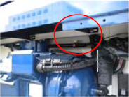
ThinLINE® Units Discharge Pressure Regulator Valve (DPRV) Removal
The purpose of the DPRV on the ThinLINE® unit is to ensure compressor lubrication is maintained when operating under low load, low ambient conditions. As a result of extensive research conducted using the ML3 controller and the stepper suction modulation valve, we were able to qualify new software logic that improves oil management, allowing us to remove the DPRV and simplify the unit.
Accordingly, on ThinLINE unit model numbers (69NT40-541-xxx) with PID 2000 or greater, the DPRV has been removed from the unit.
These units must have software version 5147 or greater. All units have a label on them advising of the minimal software requirement. Units operating with software version 5147 or greater with a stepper modulation valve and ML3 controller will operate as follows:
•Establishment of a minimum SMV closure position based on ambient condition. This maintains a minimum suction pressure to ensure compressor does not start in a vacuum, pumping the oil out of the compressor. This may result in compressor cycling under low ambient. low loads.
•CPC (Condenser Pressure Control) logic will operate solely on condenser pressure removing the timer requirement in the current logic. This will increase the discharge pressure maintaining required compressor oil pressure / flow.
•Addition of a Trim Heat mode of operation (heat + cooling) for ambient < 50°F (10°C). This will ensure compressor “on” time is equal to or greater than “off” time to keep compressor oil temperature constant (both heat and cool indicator lights will be lit).
If a DPRV requires servicing in a unit, then it can be removed from the unit provided it has an ML3 controller with software version 5147 or greater and a stepper modulation valve. Otherwise, the DPRV will require replacement. If the unit has both of these and the logic is installed, then the DPRV will operate in parallel to the new logic.
The Trim Heat logic was added to all ML3 ThinLINE controlled units (inclusive of the analog suction modulation valve).
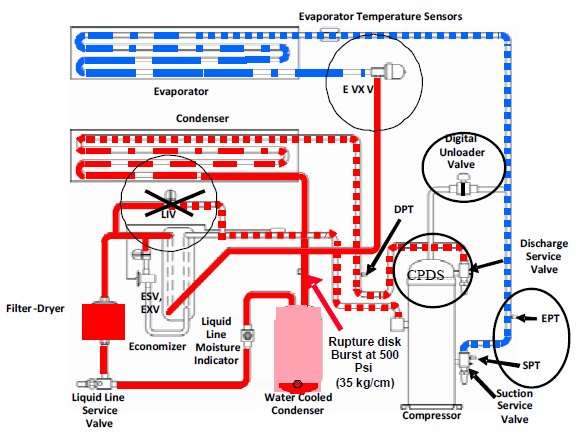
PrimeLINE® Units Troubleshooting Tips
Troubleshooting the PrimeLINE units by performing the following checks: Liquid Injection Valve (LIV) check, Evaporator Pressure Transducer (EPT) and Suction Pressure Transducer (SPT) check, Digital Unloader Valve (DUV) coil check, Digital Unloader Valve (DUV) and Electronic Expansion Valve (EEV) check, Dome Temperature Sensor (CPDS) check.
Liquid Injection Valve (LIV) Check:
The LIV is no longer required in the PrimeLINE® unit with software version 5343 and greater (refer to TECHLINE volume 14, number 2).
Evaporator Pressure Transducer (EPT) and Suction Pressure Transducer (SPT) Check:
Run Pretrip 5; if pretrip P5-9 passes, then the transducers are good.
If P5-9 fails, then calibrate the manifold gauges before connecting to the suction service valve. Connect the gauges and record the readings. If one of the code 12 readings is different from the readings of the gauges by more than +/- 1.7 psig (0.12 bar), then replace the failed transducer (EPT or SPT).
If one pressure transducer fails, then it is not critical because with software versions 5345 and greater, either EPT or SPT alternates as a backup for the failed transducer. Replacement of failed PT can be done during normal maintenance.
Digital Unloader Valve (DUV) Coil Check:
Unplug the EC connector and measure the resistance of the DUV coil between the points K1-K2 of the EC connector. The value of the resistance should be: 14.8 +/- 0.74 Ohm at 25°C (77°F).
The DUV coil is not an “in route” critical part. Failure of the coil will cause the unit to operate in high capacity mode with no compressor unloading; the compressor will cycle on and off to maintain setpoint. Replacement can be done during normal maintenance.
Digital Unloader Valve (DUV) and Electronic Expansion Valve (EEV) Check:
With the unit operating in the Cool Mode (set point below the temperature of the box), select code 41.
1.Press the “ENTER” key to select tIM (time) and set the desired time up to 5 min. at 30 sec. intervals using the arrow keys.
2.Press the “ENTER” key to select PCnt (percentage) and set the desired percentage up to “50” using the arrow keys, then press “ENTER.”
The suction pressure should fluctuate with DUV energized/de-energized. If there is no change in suction pressure (Cd12 readings or suction gauge reading), then the DUV could be faulty. Return PCnt to “AUTO” using the arrow key and press “ENTER.”
3.Press the “ENTER” key to select EEV and set to “25” using the arrow key and press “ENTER.”
Watch the suction pressure, and then set the EEV to “3” using the arrow key and press “ENTER.” The suction pressure and the compressor current should drop. If the suction pressure and the compressor current do not drop, the EEV could be faulty.
The EEV is a critical part for all conditions and must be replaced. An EEV failure produces loss of temperature control, flooding or low suction pressure shutdown.
Dome Temperature Sensor (CPDS) Check:
Unplug the EC connector and measure the resistance of the discharge temperature sensor between the points A3-B3 of the EC connector. The thermistor should conform to the curve characteristics outlined in the table below.
|
Temperature C / F |
Resistance (k Ohm) |
|---|---|
|
-10 / 14 |
476 |
|
-5 / 23 |
364 |
|
0 / 32 |
281 |
|
5 / 41 |
218 |
|
10 / 50 |
171 |
|
15 / 59 |
135 |
|
20 / 68 |
107 |
|
25 / 77 |
86 |
|
30 / 86 |
69 |
|
35 / 95 |
56 |
|
40 / 104 |
46 |
|
45 / 113 |
38 |
The CPDS is used for compressor dome temperature control. Failure of CPDS may lead to overheating of the compressor. If the CPDS fails and the unit is in the frozen range (return air temperature below -18.4°C (-1°F) / 50HZ or -20°C (-4°F) / 60 HZ and the ambient is greater than 43°C (110°F), then it must be replaced immediately.
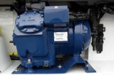
Product Update - ThinLINE® Reciprocating Compressor Sight Glass
In alignment with the EliteLINE® and PrimeLINE scroll units, Carrier Transicold has removed the oil level sight glass from the reciprocating compressor in the ThinLINE model units. This action was taken to eliminate unnecessary field adjustment of oil levels resulting in too much, or too little, oil being found in the system.
Removal of the sight glass will affect only OEM (new equipment only). Replacement compressors will continue to have a sight glass.
Note that the factory oil charge in the system is sufficient enough to offset minimum loss of oil when minor leaks of refrigerant occur.
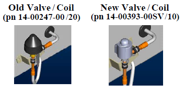
Product Update - Suction Modulation Valve (SMV)
The stepper motor suction modulation valve is used to regulate the flow of refrigerant. Signals are sent to the stepper motor inside this valve to open and close. By closing or opening, the valve increases or decreases pressure in the evaporator. This in turn raises or lowers evaporator temperature.
Initially, the EliteLINE and ThinLINE unit models used different suction modulation valves, however, starting with serial number MSS 60316266, the suction modulation valve has been standardized between these models. The ThinLINE model was changed to use the same valve as the EliteLINE model. With these valves, the bodies or complete assemblies are interchangeable, but the piston and motor assemblies are not.
No controller operational software change is required.
It is recommended that if you have a ThinLINE unit-only ship kit, that you evaluate the need of adding the EliteLINE unit piston and motor assembly (pn 14-00353-20) to the kit.
Product Update - Electronic Expansion Valve (EEV)
Starting with PrimeLINE models (69NT40-561-xxx / PID > 2009), the electronic expansion valve was changed. The complete assemblies are interchangeable but the coils that drive the valves are not
It is recommended that if you are adding a new PrimeLINE unit to your fleet, you should evaluate your ship kit needs to be sure that this new assembly is added.
Defrost Pulsing Logic
Starting with software 5147 and 5347 (ML3 controllers), a new unit configurable defrost pulsing logic was implemented. As part of this logic, a new user selectable option was added to code select 27 (puls). When this mode of defrost is selected, the defrost interval will set to 6 hrs and cycle the evaporator fans on and off during defrost when the setpoint is -18.1° C (-0.6° F) and below.
If the set point is -18°C (-0.5°F) and above, the fans will not cycle on and off during defrost and the defrost interval is set to “Auto”.
This option was added to ensure successful defrosts when carrying deep frozen cargo under high humidity conditions.
This feature will be added to the ML2i controller as part of a release later this year.
Troubleshooting Tier 4i Engine Control Module
What does the blinking LED on the bottom of the engine control module mean on the Undermount and Clip On genset (69UG15/RG15) with PID’s greater than 1400?
The blinking light is actually identifying a fault that has occurred with the operation of the engine. This indicator light will illuminate with different combinations of long and short flashing patterns, which can be used to identify the component that may have failed or has a fault. The chart below shows the series of those patterns, the failure mode and the area to troubleshoot.
|
Signal Pattern (LED Light) |
Failure |
Check |
|
1 Long and 1 Short |
Overspeed |
Harness, Speed Sensor, Run Solenoid |
|
2 Long and 1 Short |
Speed Sensor Disconnected |
Harness, Speed Sensor |
|
2 Long and 2 Short |
Run Solenoid Malfunction (Circuit Short) |
Harness, Speed Sensor |
|
2 Long and 3 Short |
Run Solenoid Malfunction (Circuit Open) |
Harness, Speed Sensor |
|
2 Long and 7 Short |
Excess Voltage |
Battery Charging System |
Listed are the remaining scheduled training schools for 2010. These schools are subject to a minimum requirement of 12 students to avoid cancellation. Please check to ensure the class has met this requirement prior to confirming your travel reservations.
|
Start Date |
Program |
Location |
|
|
APO |
9/6/2010 |
1-Week Container |
Auckland, NZ |
|
9/13/2010 |
1-Week Container |
Melbourne, Australia |
|
|
11/15/2010 |
1-Week Container |
Yokohama, Japan |
|
|
11/22/2010 |
Advanced 3-Day Container Product Update |
Davao, Philippines |
|
|
11/25/2010 |
2-Day Gen Set |
Davao, Philippines |
|
|
ETO |
9/13/2010 |
Advanced 3-Day Container Product Update |
South Africa |
|
9/16/2010 |
2-Day Gen Set |
South Africa |
|
|
9/20/2010 |
Advanced 3-Day Container Product Update |
West Africa |
|
|
9/23/2010 |
2-Day Gen Set |
West Africa |
|
|
LAO |
8/23/2010 |
1-Week Container |
Santa Marta, Colombia |
|
10/5/2010 |
Advanced 3-Day Container Product Update |
Buenos Aires, Argentina |
|
|
10/11/2010 |
1-Week Container |
San Pedro Sula, Honduras |
|
|
10/18/2010 |
2-Day Gen Set |
Guatemala |
|
|
NAO |
10/6/2010 |
Advanced 3-Day Container Product Update |
Vancouver, British Columbia |
|
10/11/2010 |
1-Week Container |
Oakland, CA |
|
|
11/3/2010 |
Advanced 3-Day Container Product Update |
Montreal, Canada |
|
|
11/9/2010 |
Advanced 3-Day Container Product Update |
Elizabeth, NJ |
Listed below are the most current software release versions for operating and working with Carrier Transicold container units. Prior to upgrading units you should seek agreement from the equipment owners.
Recip Unit (ML2i/ 5146, ML3/5147)
Reciprocating Unit (ML2) – 1207
Controlled Atmosphere – 3114
DataLINE – 1.9.1
DataBANK – 0513