Installation and Removal
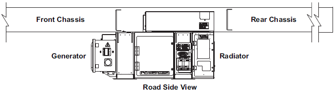
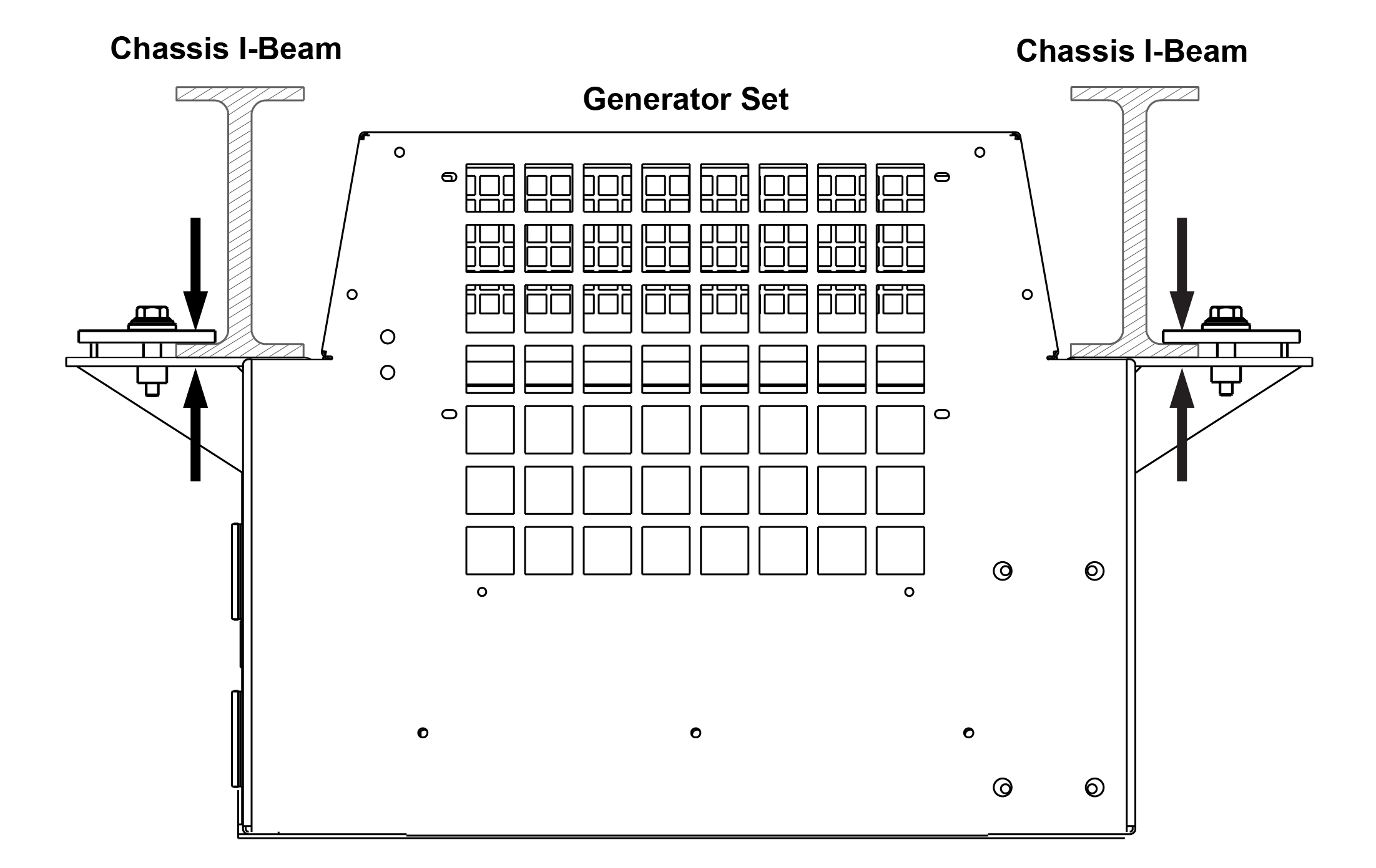
The generator set is mounted under the center of the trailer chassis and is easily handled with a fork lift truck capable of handling 3,000 pounds. The fork lift pockets provided are accessible from either side. Mounting clamps, shown in Figure 2.1, are designed to be attached to outside I-beam flanges only. Maximum chassis width is 38 inches on center.
Figure 2.1 Standard Mounting Clamp Hardware
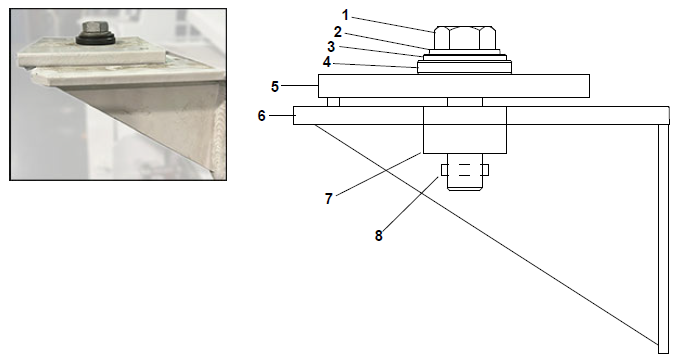
1)Mounting Bolt
2)Washer, Spherical
3)Washer, Spherical, Male
4)Washer, Spherical, Female
5)Mounting Plate
6)Generator Frame
7)Tee Nut
8)Roll Pin
- - - - -
Procedure:
1.Inspect hardware, Figure 2.1, to ensure all items are not damaged and in place. It is recommended to use Carrier provided hardware.
NOTE: Mounting bolts are Grade 5 steel with 3/4-10 UNC-2A threads.
2.Loosen the mounting bolts enough to push the mounting plates to the outermost position.
3.Place forks into the fork lift pockets of the generator set.
4.Using the fork truck, center the generator set under the chassis between the rails.
5.Lift the forks up so that both sides of the generator set mounts are touching the chassis I-beam.
6.Slide the mounting plates fully onto the chassis I-beams and torque mounting bolts to a minimum of 200 ft-lbs (271 Nm), in a cross pattern. The torque range is 200 to 260 ft-lbs. (271 to 352 Nm).
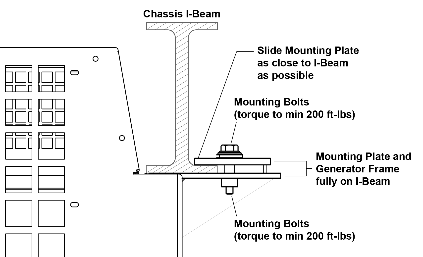
Mis-alignment with the chassis and generator set mount may result in a false torque.
If a bolt is heavily corroded, spray the hardware with a corrosive cleaner with lubricant.
7.Back the fork truck from the unit, removing the forks from the unit.
8.Perform a torque check on all four mounting bolts with the fork truck removed. Minimum of 200 ft-lbs.
NOTE: It is important to ensure the forklift is removed when checking torque on the genset. Keeping the forklift installed can cause a false torque reading due to the forks holding the unit down, possibly resulting in the unit not being properly secured to the chassis.
If the genset is removed for PM or service, it is recommended that the hardware be sprayed with a rust inhibiting lubricant prior to re-installation. Additionally, the tool used to check torque should be periodically checked for accuracy.
1.Disconnect the power cable to the generator set (if connected).
2.With a fork lift in position and safety chain attached, slide the mounting plates back sufficiently to clear the chassis.
3.Lower and remove the generator set.