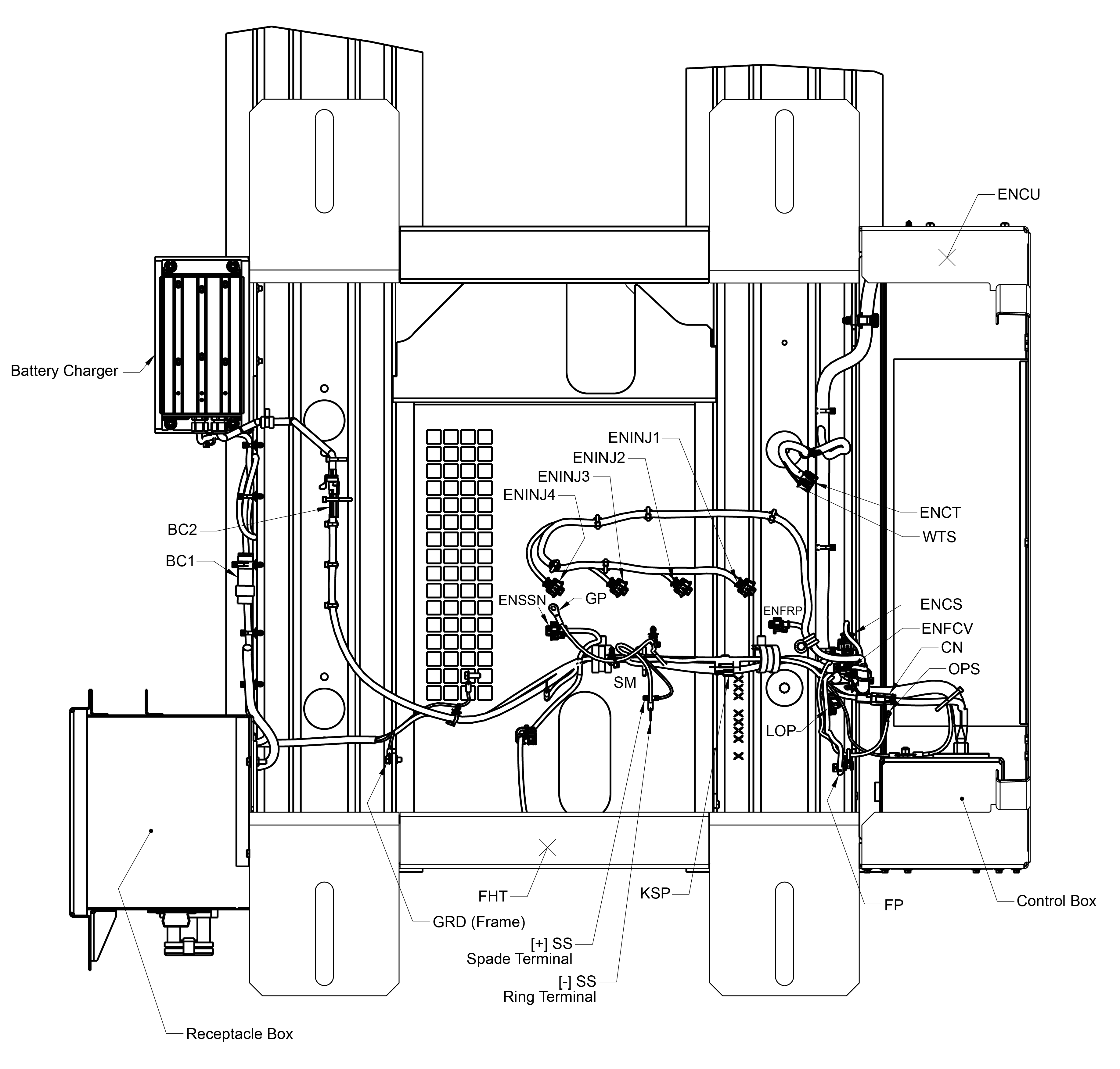
1)BC1: Battery Charger Input (HV Connector)
2)BC2: Battery Charger Output (LV Connector)
3)CN - Voltage Controller (HV Connector)
4)ENCS - Engine Camshaft Position Sensor
5)ENCT - Engine Coolant Temperature
6)ENCU - Engine Control Unit
7)ENFCP - Engine Fuel Control Valve
8)ENFRP - Engine Fuel Rail Pressure
9)ENINJ1 - Engine Fuel Injector 1
10)ENINJ2 - Engine Fuel Injector 2
11)ENINJ3 - Engine Fuel Injector 3
12)ENINJ4 - Engine Fuel Injector 4
13)ENSSN - Engine Speed Sensor (Correct)
14)FHT - Fuel Heater, Integrated
15)FP - Fuel Pump
16)G - Generator
17)GP - Glow Plug
18)GRD - Ground
19)KSP - Kubota Service Port
20)LOP - Low Oil Pressure Switch
21)OPS - Oil Pressure Sender
22)SM - Starter Motor
23)SS - Starter Solenoid
24)WTS - Water Temperature Sender
- - - - -
|
Terminal Number |
Abbreviation |
Formal Name |
|---|---|---|
|
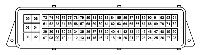
1 |
P (-) |
Power ground |
|
2 |
P (-) |
Power ground |
|
3 |
#1/4 INJ (+) |
Injector cylinder #1 / #4 VCC |
|
4 |
+B |
Battery |
|
5 |
#2/3 INJ (+) |
Injector cylinder #2 / #3 VCC |
|
6 |
+B |
Battery |
|
7 |
#4 INJ (-) |
Injector cylinder #4 ground |
|
8 |
NE (-) |
Crankshaft position sensor ground (ENSSN) |
|
11 |
CT (-) |
Coolant temperature sensor ground (ENCT) |
|
14 |
Engine Speed Relay 1500/1800 (ENSR) |
|
|
29 |
#3 INJ (-) |
Injector cylinder #3 ground |
|
32 |
RP (+) |
Rail pressure sensor VCC (ENFRP) |
|
33 |
CT |
Coolant temperature sensor (ENCT) |
|
39 |
NE (+) |
Crankshaft position sensor VCC (ENSSN) |
|
42 |
ST SW |
Starter switch |
|
44 |
G (-) |
Camshaft position sensor ground (ENCS) |
|
45 |
G (+) |
Camshaft position sensor VCC (ENCS) |
|
46 |
G |
Camshaft position sensor (ENCS) |
|
47 |
OL SW |
Oil pressure switch (OPS) |
|
48 |
WR LP |
Engine Warning Lamp |
|
50 |
M RY |
Main Relay |
|
51 |
#2 INJ (-) |
Injector cylinder #2 ground |
|
54 |
RP |
Rail pressure sensor (ENFRP) |
|
62 |
CAN2 H |
CAN2 High |
|
63 |
CAN2 L |
CAN2 Low |
|
65 |
CAN1 L |
CAN1 Low |
|
66 |
CAN1 H |
CAN1 High |
|
68 |
ST RY |
Starter Relay |
|
70 |
GL RY |
Glow Relay |
|
71 |
IG SW |
Ignition Switch |
|
73 |
#1 INJ (-) |
Injector cylinder #1 ground |
|
75 |
NE |
Crankshaft position sensor (ENSSN) |
|
76 |
RP (-) |
Rail pressure sensor ground (ENFRP) |
|
89 |
SCV (-) |
Suction control valve ground (SCV) |
|
Signal Name |
Description |
Reference Value / Behavior |
|---|---|---|
|
Rotary / Pulse Signal |
||
|
Engine Speed [rpm] |
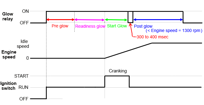
Indicates engine RPM via a signal from the crankshaft position sensor. If this signal fails, the camshaft position sensor signal is used. This is a standard value for various controls |
When engine stopped (switch in RUN): 0 is displayed. When engine running: engine speed is displayed. |
|
Vehicle Speed [km/h] |
Indicates vehicle speed via a signal from the vehicle speed sensor (CAN). |
This is not currently being used. |
|
Analog Signal |
||
|
Accelerator Pedal Position [%] |
Indicates accelerator position via the accelerator sensor or CAN signal. One standard value that determines fuel injection quantity |
This is not currently being used. |
|
Accelerator Pedal Position Sensor 1 Output Voltage [V] |
Indicates accelerator sensor output voltage value (system 1) Used to calculate accelerator position |
This is not currently being used. |
|
Accelerator Pedal Position Sensor 2 Output Voltage [V] |
Indicates accelerator sensor output voltage value (system 2) Used to calculate accelerator position |
This is not currently being used. |
|
Coolant Temperature [°C] |
Indicates coolant temperature via the coolant temperature sensor signal Used for deciding start mode when cold, and for various controls, including CRS controls, such as injection timing |
About 4.24 V at -20°C (-4°F) About 3.40 V at 0°C (32°F) About 2.36 V at 20°C (68°F) About 0.88 V at 60°C (140°F) About 0.47 V at 80°C (176°F) About 0.39 V at 100°C (212°F) About 0.12 V at 120°C (248°F) |
|
Coolant Temperature Sensor Output Voltage [V] |
Indicates coolant temperature sensor output voltage value Used to calculate coolant temperature |
About 4.24 V at -20°C (-4°F) About 3.40 V at 0°C (32°F) About 2.36 V at 20°C (68°F) About 0.88 V at 60°C (140°F) About 0.47 V at 80°C (176°F) About 0.39 V at 100°C (212°F) About 0.12 V at 120°C (248°F) |
|
Atmospheric Pressure [kPa] |
Indicates atmospheric pressure via the atmospheric pressure sensor signal Used in CRS controls, such as fuel injection amount |
At flat ground: 100 (standard atmospheric pressure As altitude gets higher, the value gets lower |
|
Atmospheric Pressure Sensor Output Voltage [V] |
Indicates atmospheric pressure sensor output voltage value Used to calculate atmospheric pressure |
About 4.0 V at 101 kPa |
|
Battery Voltage [V] |
Indicates battery voltage |
When engine stopped (switch in RUN): around 12. When engine cranking: lower When engine running: around 14. |
|
Digital Signal |
||
|
Key Switch |
Indicates ignition switch ON/OFF state |
Always ON when switch is in RUN, regardless of engine operating state |
|
Start Switch |
Indicates ignition switch start signal ON/OFF state Indicates cranking being done |
When engine cranking: ON is displayed Otherwise: OFF |
|
Neutral Switch |
Indicates neutral position state Neutral switch or CAN signal |
This is always Neutral ON.. |
|
Basic Control Signal |
||
|
Final Fuel Injection Quantity [mm3/st] |
Indicates fuel injection amount per cylinder calculated by the ECU based on various sensors: such as engine speed, coolant temperature and atmospheric pressure |
When engine stopped (switch in RUN): less than 0 During no-load maximum speed: about 4 to 6 |
|
Target Rail Pressure [MPa] |
Indicates standard rail pressure calculated by the ECU in order to output the specific output and RPM |
When engine stopped (switch in RUN): 0 During no-load maximum speed: about 90 |
|
Actual Rail Pressure [MPa] |
Indicates rail pressure via the rail pressure sensor signal Used in CRS controls |
Follows target rail pressure |
|
Rail Pressure Sensor Output Voltage [V] |
Indicates rail pressure sensor output voltage Used to calculate actual rail pressure |
Proportional to actual rail pressure When engine stopped (switch in RUN): about 0.3 V During no-load maximum speed: about 1.6 V |
|
Target Suction Control Valve (SCV) Current [mA] |
Indicates target SCV current value Used in CRS controls |
Proportional to target SCV current value When engine stopped (switch in RUN): about 0 mA During no-load maximum speed: about 1400 mA |
|
Actual Suction Control Valve (SCV) Current [mA] |
Indicates actual SCV current value Used in CRS controls |
Follows target SCV current value |
|
Idle Control Target [rpm] |
Indicates target engine speed during idling |
This is a fixed value, it does not change Actual engine speed at idle is close to this value |
|
Engine Stop Flag |
Indicates ON/OFF state of engine stop flag Indicates engine stop state |
When engine stopped (switch in RUN): ON When engine running: OFF |
|
Low Temperature Start Mode Flag |
Indicates ON/OFF state of low temperature start mode flag Cold start mode trigger: a mode that compensates fuel injection amount at start when coolant temperature and/or engine speed are low. |
When engine stopped (switch in RUN): OFF When engine cranking: ON When engine running: OFF |
|
Actuator |
||
|
Glow Relay |
Indicates glow relay ON/OFF state Indicates ON when glow plugs (or intake air heater) are energized |
When ON in cold start mode: ON When OFF in cold start mode: OFF |
|
Other |
||
|
Hour meter [h] |
Indicates the hour meter value recorded to the ECU |
Hours of ECU operation displayed |
|
Source Address of TSC1 |
Indicates CAN communication address settings *May be disabled under some specifications |
Always show: 0 |
|
Parking SW |
Indicates parking switch ON/OFF state Parking switch signal or CAN signal |
Always show: OFF |
|
Oil Pressure SW |
Indicates oil pressure switch ON/OFF state Oil pressure switch signal |
When ignition switch ON (engine stopped): OFF When engine operating: ON |
|
Target Speed of Isochronous Control [rpm] |
Indicates target engine speed under isochronous control |
Will show either 1500 or 1800 for 50-60 Hz. |