The ECM Service Tool, Figure 4.1, is diagnostic software that can test the functionality of individual EES components initiate regeneration, display alarm codes, provide current sensor readings. retrieve data from the ECM, and more.
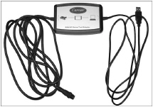
The ECM Service Tool software v2.0.28 is required to communicate with the ECM. This can be downloaded from the Carrier Transicold website. With the software installed, connect the computer to the ECM through an ECM CAN Adapter, Figure 4.2, part number 07-00533-01.
When the ECM Service Tool program is first opened and the USB connector from the ECM CAN Adapter is connected to the computer, a message will indicate that a new driver has been installed. If the driver has not been installed properly, the software will automatically complete driver installation.
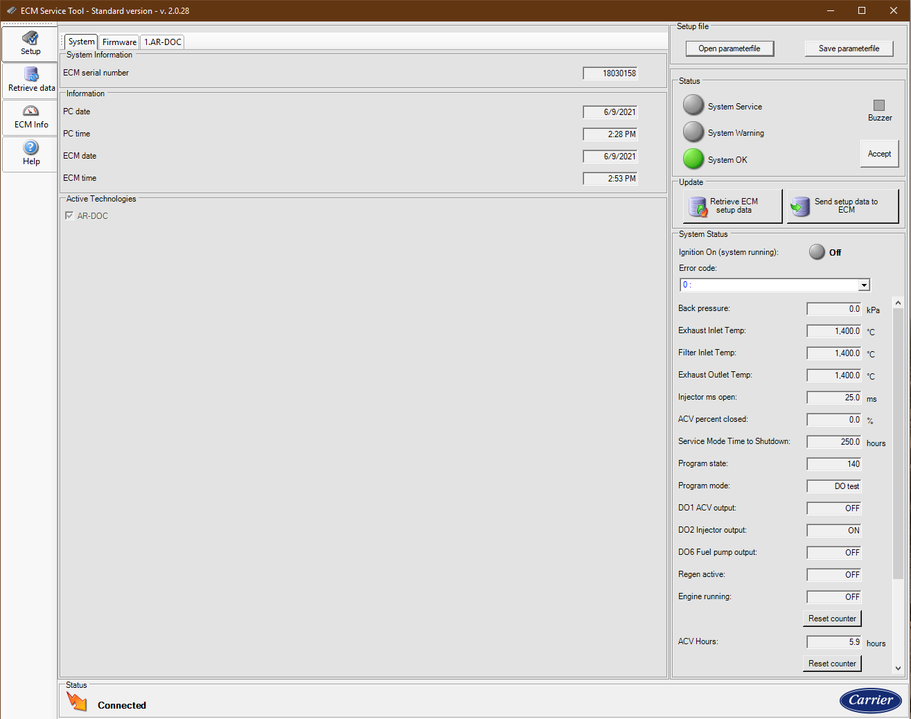
The ECM Service Tool will setup the port the first time you open the program. When the ECM is communicating, the status on the bottom left side of the screen will display "Connected". Refer to Figure 4.3.
Figure 4.3 ECM Service Tool - Connected

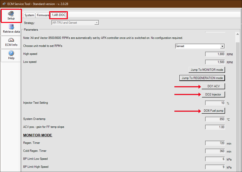
Component check, Figure 4.4, is for testing the functionality of individual EES components by cycling the components on and off. Each component will energize for one cycle. The engine must be off.
When checking components, disengage the starter so that the unit will not start. Components should be tested with switch power only.
1.From the Setup screen, click on the AR-DOC tab.
2.Click the DO1 ACV button once to activate ACV. The ACV will go through one cycle. As the ACV cycles, the motor will make a slight, audible sound which indicates that the valve is working properly.
3.Click the DO1 ACV button again to deactivate the ACV.
1.From the Setup Screen, click on the AR-DOC tab.
2.Click the DO2 Injector button once to activate the injector. When the injector is activated, it will make a slight, audible click which indicates that the injector is working properly.
3.Click the DO2 Injector button again to deactivate the injector.
1.From the Setup Screen, click on the AR-DOC tab.
2.Click the DO6 Fuel pump button once to activate the fuel pump. As the fuel pump cycles, the pump motor will make a slight, audible sound which indicates that the fuel pump is working properly.
3.Click the DO6 Fuel pump again to deactivate the fuel pump.
Do not activate the Injector (Doser) and Fuel Pump at the same time. This will result in raw fuel being sprayed into the exhaust system.
Figure 4.4 ECM Service Tool - Component Check
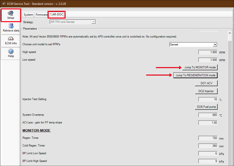
4.3Initiating a Manual Regeneration
A manual regeneration can be initiated from the ECM service tool. Refer to Figure 4.5.
Refer to Section 3.7 for more details on the regeneration process.
1.From the Setup Screen, click on the AR-DOC tab.
2.Start the unit and allow the unit to run for 15 minutes to warm up the DPF.
3.Click the “Jump TO REGENERATION mode” button to initiate regeneration. The system will automatically start a complete regeneration as long as the following conditions are met:
•No active alarms are present in the Error Code listing.
•Back pressure is below 30kPa.
4.To stop a regeneration, click the “Jump To MONITOR mode” button.
Figure 4.5 ECM Service Tool - Manual Regeneration
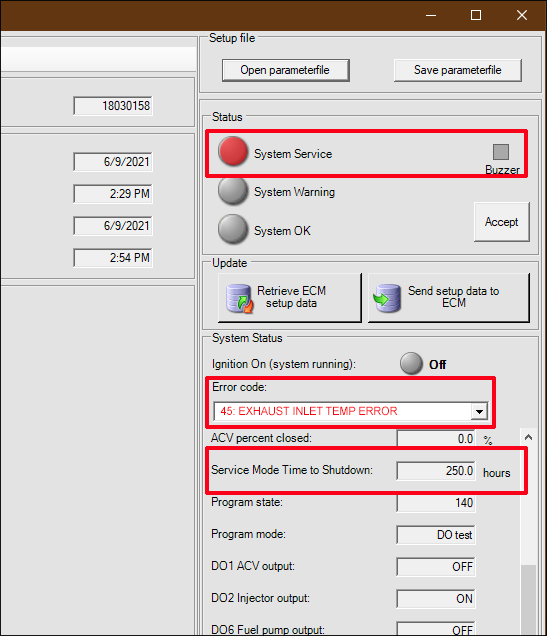
Alarm conditions where the EES becomes inoperable will initiate a 250 hour timer. After 250 hours, the unit will shut down until the system is repaired by a qualified technician. Once the alarm condition is corrected, the EES Service Light will go from Amber to Green and the timer will be reset. Refer to Figure 4.6.
Refer to Section 5.1 for a list of alarms and troubleshooting information.
1.From the Setup Screen, click on the AR-DOC tab.
2.Alarms can be read with the unit running or turned off, as long as battery power is hooked up.
Red: Active alarm
Blue: Alarm has been corrected
Green: Alarm has been cleared
Figure 4.6 ECM Service Tool - Alarms
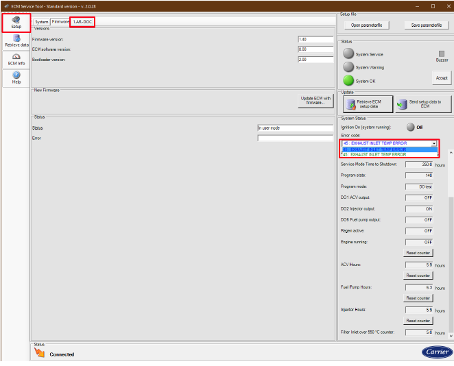
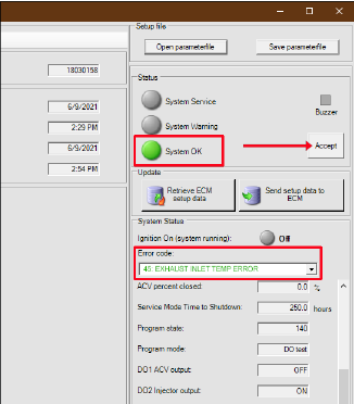
3.When an alarm occurs, the error code is logged in the drop down box. It is listed in red to indicate that it is an active alarm. The System Service indicator turns red. Alarm conditions where the EES becomes inoperable will initiate a 250 hour timer. After 250 hours, the unit will shut down until the system is repaired by a qualified technician. Refer to Figure 4.7.
Figure 4.7 ECM Service Tool - Alarms Active
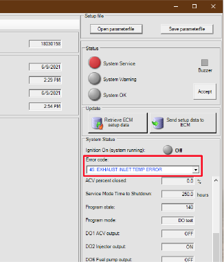
4.After the alarm has been corrected, the alarm text turns blue. Refer to Figure 4.8.
Figure 4.8 ECM Service Tool - Alarms Corrected
5.Once an alarm is corrected, turn the unit switch off and on. Then, click on the Accept button. Verify that the alarm text turns green and the System Indicator turns green. Refer to Figure 4.9.
Figure 4.9 ECM Service Tool - Alarms Cleared
The ECM Service Tool can display current readings for the EES sensors on the Setup Screen from the AR-DOC tab. Refer to Figure 4.10.
Figure 4.10 ECM Service Tool - Sensor Readings
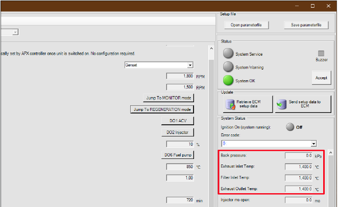
The following sensors are monitored:
•Exhaust Inlet Temperature Sensor (ESEIT)
•Filter Inlet Temperature Sensor (ESFIT)
•Filter Outlet Temperature Sensor (ESFOT)
•Filter Back Pressure Sensor (ESFP)
With the unit off, once exhaust system temperature has stabilized check sensor temperatures for Exhaust Inlet, Filter Inlet, and Filter Outlet. All readings should be within 1 or 2 degrees of each other.
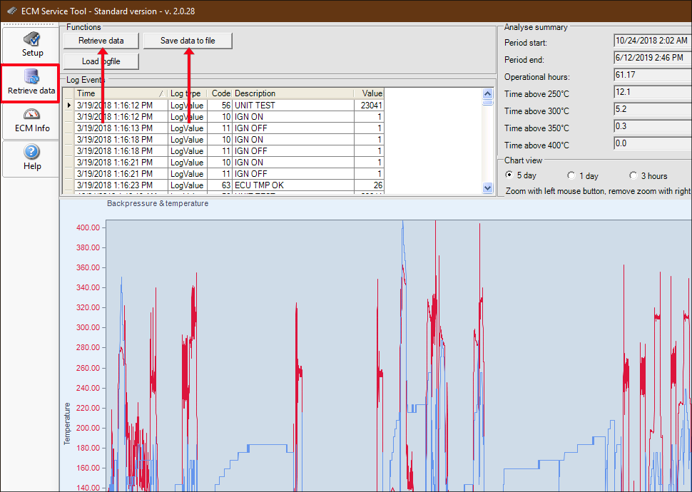
An EES download may be necessary for troubleshooting the EES. Refer to Figure 4.11.
1.From the Retrieve Data screen, click on the Retrieve data button. The “Receiving log data” dialog box will be displayed.
2.Once the data has been downloaded, the screen will update to show the log events. To save the data, click “Save data to file.”
3.The “Browse for folder” dialog box will appear. Find a location to save the files to, and then click “OK.”
4.Once the log data is downloaded, a dialog box will show “Logfiles saved.”. Click OK.
5.After the download is complete, two text files and one zip file will be saved.
Figure 4.11 ECM Service Tool - Retrieving Data
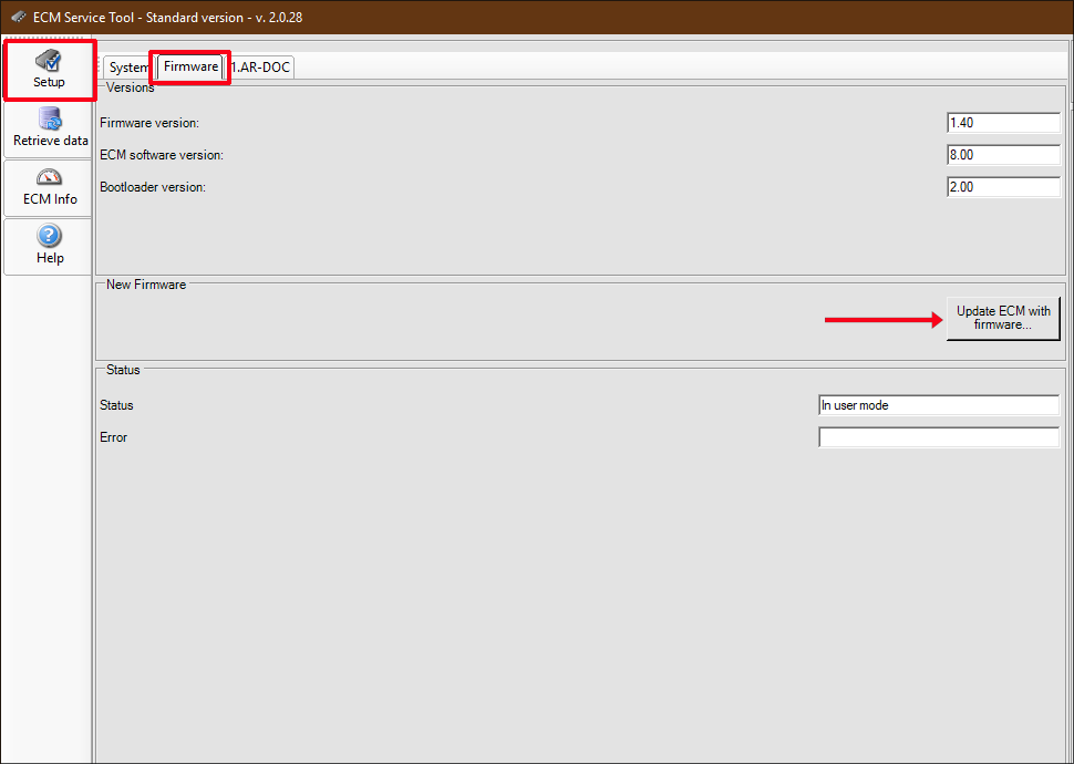
4.7Programming the ECM with New Software
If the ECM needs to be updated with new firmware, use the ECM Service tool to do it. Refer to Figure 4.12.
1.From the Setup screen, click on the Firmware tab.
2.Click on the “Update ECM with firmware” button. A window will prompt to locate the new software file.
3.Choose the new software file and click Open. A window will open showing progress of the download.
4.Once the update is complete the message “Update successful” is displayed. Click OK.
5.Confirm that the software / firmware revision has been updated.
Figure 4.12 ECM Service Tool - Software Update