Description
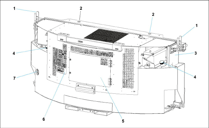
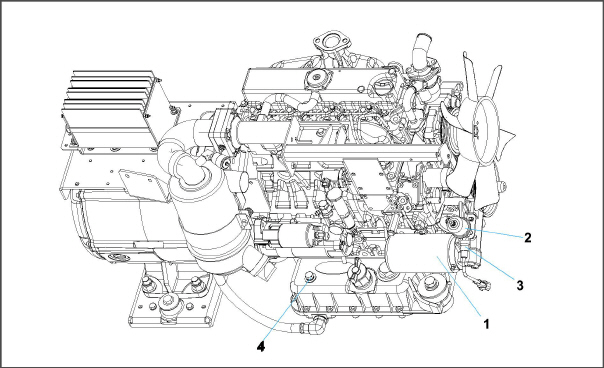
The Carrier Transicold model 69RG15 Series 22 diesel-driven generator set provides a constant electrical power supply for all-electric refrigeration units. The 69RG15 is a a clip-on unit (see Figure 2.1, Figure 2.2) mounted to the front of the container either by pin mounts located on the top channel or by optional clamp mounts located on either side of the generator set.
The generator set consists of a diesel engine directly connected to an alternating current generator and mounted in a structural steel frame. The engine is a vertical, in-line, four cylinder diesel manufactured by Kubota. The generator is a 15 kW, permanent, single winding, dual bearing type that supplies nominal 50/60Hz power.
Electrical controls are mounted in a control box with operating controls and gauges mounted on a control panel, which also serves as the control box cover. The control panel components are protected by a deflector assembly and control box door.
1)Clamp Mounts (Optional)
2)Pin Mounts
3)Unit Nameplate (Model, Serial, PID)
4)Fuel Cap
- - - - -
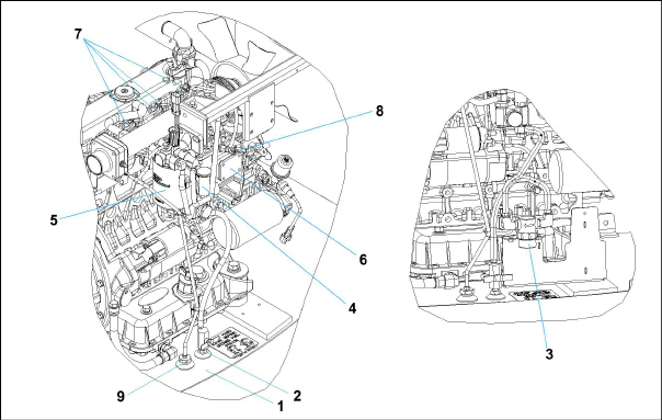
Figure 2.2 Generator Set Components - Covers Removed
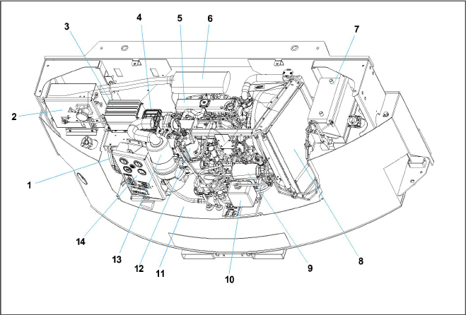
1)AC Generator
2)Receptacle Box
3)Battery Charger
4)Voltage Controller
5)Engine
6)Exhaust Muffler
7)Battery
8)Radiator
9)Oil Filter
10)Coolant Recovery Bottle
11)Fuel Tank
12)Fuel Filter / Water Separator
13)Engine Air Cleaner
14)Control Panel and Control Box
- - - - -
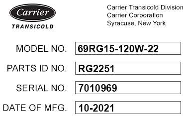
2.2Configuration Identification
Generator set identification information is provided on a unit nameplate located on the side of the unit. The label provides the generator set model number, serial number and parts identification number (PID). The model number identifies the overall configuration, while the PID provides information on specific optional equipment and differences in detailed parts.
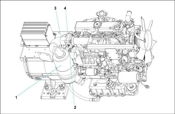
2.3Alternating Current Generator
The alternating current (AC) generator (see Figure 2.4) bolts directly to the engine and supplies nominal 50/60Hz power depending on the load requirement.
Generator sets will start at 50Hz. Once the unit is running, the voltage controller (see Section 2.3.1) will read the voltage output of the generator and adjust accordingly to keep the voltage within ISO limits. As the container becomes loaded, voltage drops and current increases, causing the generator set to adjust speed based on power demand and ambient conditions. The unit will typically run at 50Hz and vary generator output via winding selection. The speed change to 60Hz will typically occur when the ambient temperature is high and the unit is heavily loaded.
The voltage controller (VC) maintains ISO voltage via two-speed and single winding control. It regulates voltage in order to keep the generator output within ISO limits (see Table 2–3). The voltage controller and voltage controller fuses (VCF1 and VCF2) are located in the receptacle box (see Figure 2.12).
The engine (see Figure 2.4) is a vertical, in-line four cylinder diesel engine, model V2203-DI, that is directly connected to the AC generator. The diesel engine takes air, compresses it and then injects fuel into the compressed air. The heat of the compressed air ignites the fuel spontaneously.
Separately bound manuals covering the diesel engine are available:
•62-10865, V2203-DI Engine Workshop
•62-11695, V2203-DI Engine Parts List
Figure 2.4 Generator and Engine - Unidrive Assembly
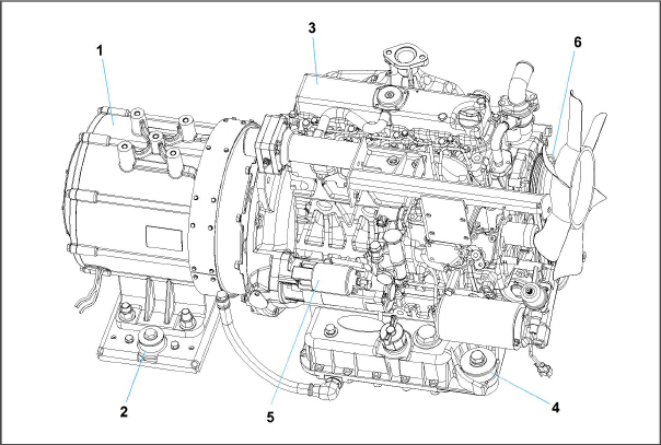
1)Generator
2)Generator Shockmount
3)Engine
4)Engine Shockmount
5)Starter
6)Poly V-Belt
- - - - -
The engine fuel system (see Figure 2.5) is a closed circuit that injects a precise amount of atomized fuel into the engine cylinders. A mechanical lift pump initially transfers fuel at low pressure from the fuel tank and through the fuel shutoff valve. An optional in-line fuel strainer can be used prior to the fuel filter / water separator to trap large particles. The fuel filter / water separator removes water and finer particles and includes a 12-volt baldwin fuel heater. Low pressure fuel then enters the injection pump, where it is compressed to higher pressures and distributed to individual fuel lines that supply each cylinder’s injector nozzle. The nozzles spray atomized fuel into the combustion chamber based on the timing of the injector pump. Any excess fuel in the nozzles not used for combustion is sent back to the fuel tank.
Figure 2.5 Fuel System Diagram
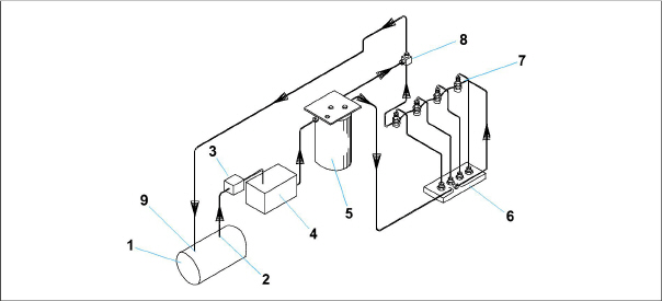
2)Fuel Tank Supply with Shutoff Valve
3)In-Line Fuel Strainer (option)
4)Mechanical Lift Pump
5)Fuel Filter / Water Separator
9)Fuel Tank Return
- - - - -
The engine requires all air to be removed the system in order to run at optimal performance. The fuel system contains a fuel pump primer on the mechanical lift pump and an air bleed screw after the injection pump, if bleeding air from the system is required.
The engine fuel tank (see Figure 2.6) is available in 120 gallon capacity.
The electronic governor controls the speed of the engine by using an electronic governor (EG) module, fuel solenoid (FS) and engine speed sensor (ESS).
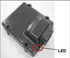
The electronic governor (EG) module (see Figure 2.7) is a solid state control module pre-programmed for 1800 RPM high speed operation and 1500 RPM low speed operation. It receives an input signal from the engine speed sensor (ESS) of the current RPM and compares this to a preset value. The electronic governor (EG) module sends a correction signal to the fuel solenoid (FS) to maintain the proper RPMs.
The electronic governor (EG) module is mounted in the control box and has an LED which may assist in diagnosing failures within the electronic speed control system. See Section 5.4 for additional troubleshooting information.
Figure 2.7 Electronic Governor Module (EG)
2.4.3Engine Lubrication System
The engine lubrication system (see Figure 2.8) supplies lubricating oil to the various moving parts in the engine. The main function is to enable the formation of a film of oil between moving parts, to reduce friction and wear.
The engine lubricating oil filter is mounted in a horizontal arrangement. The Oil Pressure Sender (OPS), located at the oil filter housing, senses lube oil pressure and transmits a signal to the Oil Pressure Gauge (OPG) located on the control panel (see Figure 2.11). The Low Oil Pressure (LOP) switch opens when engine lubricating oil pressure is observed below 1.27 kg/cm.
Figure 2.8 Engine Lubrication System
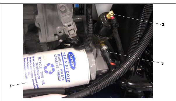
1)Oil Filter
2)Oil Pressure Sender (OPS)
3)Low Oil Pressure (LOP) Switch
4)Oil Dipstick / Fill Cap
- - - - -
2.4.4Engine Air Cleaner System
The engine air cleaner system (see Figure 2.9) utilizes a filter element to filter the engine intake air. The air cleaner effectively removes contaminants from the air stream, resulting in prolonged engine life and reduced wear on all operating engine parts. When a dry element air filter is utilized, an air filter indicator is mounted on the air filter body to indicate when the filter element needs to be replaced.
As air exits the air cleaner, it passes through the air intake heater (IH) and then enters the engine cylinder. This is done to help the engine start in cold temperatures.
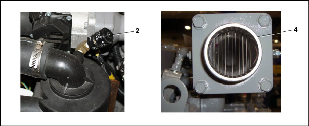
1)Air Cleaner, Dry Element
2)Air Filter Indicator
3)Air Inlet Hose
4)Air Intake Heater
- - - - -
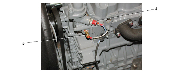
The engine cooling system (see Figure 2.10) uses extended life coolant and a radiator to keep the engine from overheating. The radiator transfers the heat from the engine coolant to the surrounding air. The water pump and the radiator cooling fan are belt-driven from the engine crankshaft. The High Water Temperature Switch (HWT) and Water Temperature Sender (WTS) monitor and regulate cooling water temperature.
Figure 2.10 Engine Cooling System
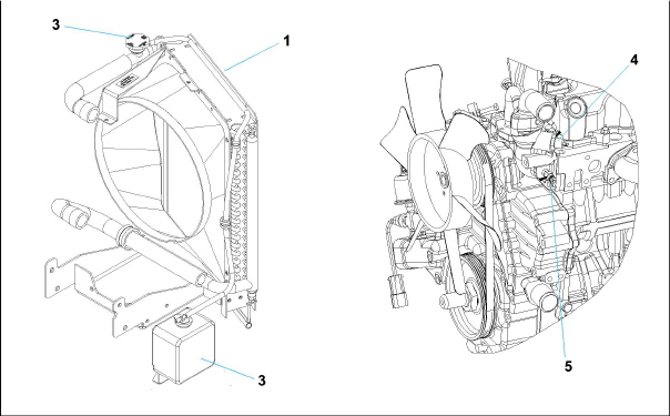
1)Radiator assembly
2)Radiator fill cap
3)Coolant recovery bottle
4)High Water Temperature Switch (HWT)
5)Water Temperature Sender (WTS)
- - - - -
2.5Battery and Battery Charging System
The battery provides 12 VDC power to the starter motor. It also provides the initial voltage for the intake heater (IH) until the unit starts. The solid state battery charger is powered by the generator, and this input is protected by fuses located in the receptacle box. The battery charger produces a tapered charge (40 amps maximum) and is designed not to overcharge the battery. See Figure 2.2 for location of components.
2.6Control Panel and Control Box Components
The control panel and control box (see Figure 2.11) contain components required for monitoring and controlling the generator set unit.
The water temperature gauge (WTG) observes water operating temperature. Once the unit has achieved normal running temperature, the coolant temperature is between 82 - 96°C. The high water temperature (HWT) switch senses engine water temperature and transmits a signal to the water temperature gauge (WTG).
The oil pressure gauge (OPG) observes normal operating engine oil pressure. Normal oil pressure is 3.3 to 5.2 kg/cm2. The oil pressure sender (OPS) (see Figure 2.8), located at the oil filter housing, senses lube oil pressure and transmits a signal to the oil pressure gauge (OPG).
The total time meter (TT) calculates the total hours the unit has been running, which provides an accurate readout of accumulated engine running time. This data can be used to establish proper maintenance schedules (refer to Table 6–1).
The ammeter (A) indicates the rate of charge or discharge of the battery charging system. The battery charging system is composed of the battery and the battery charger, either solid state or alternator. During start up, the intake heater (IH) draws approximately 42 amps.
The intake heater switch (HS) is a momentary switch. When held in the PREHEAT position, the switch allows approximately 42 amps of battery current to flow into the intake heater, which preheats the air within the intake manifold and allows the engine to start. After starting the engine, the intake heater switch should continue to be held in the ON position for approximately 5 seconds until the engine has developed enough oil pressure to close the oil pressure safety switch.
The ignition switch (IGN) is a momentary switch that has OFF/ON/START positions. When held in the START (ignition) position, it energizes the starter motor solenoid, which in turn allows the starter motor to crank the engine. The switch is released to the RUN position once the engine has started.
The intake heater timer (IHT) continues to supply power to the intake heater (IH) for 3 minutes after initial start-up.
The starter solenoid timer (SST) limits the amount of time that the starter can be engaged to 15 seconds. If the starter is manually engaged for more than 15 seconds, power will be cut to the starter. Once power has been removed, the starter can again be engaged for up to 15 seconds.
Figure 2.11 Control Panel and Control Box
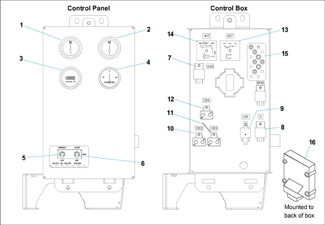
1)Water Temperature Gauge (WTG)
2)Oil Pressure Gauge (OPG)
3)Total Time Meter (TT)
4)Ammeter (A)
5)Intake Heater Switch (HS)
6)Ignition Switch (IGN)
7)Starter Solenoid Relay (SSR)
8)Safety Relay (S)
9)Intake Heater Relay (HR)
11)Circuit Breaker (CB3)
12)Circuit Breaker (CB4)
13)Starter Solenoid Timer (SST)
14)Intake Heater Timer (IHT)
15)Ground Studs
16)Electronic Governor Module (EG)
- - - - -
The Receptacle box (see Figure 2.12) contains components required for monitoring and controlling the Genset unit.
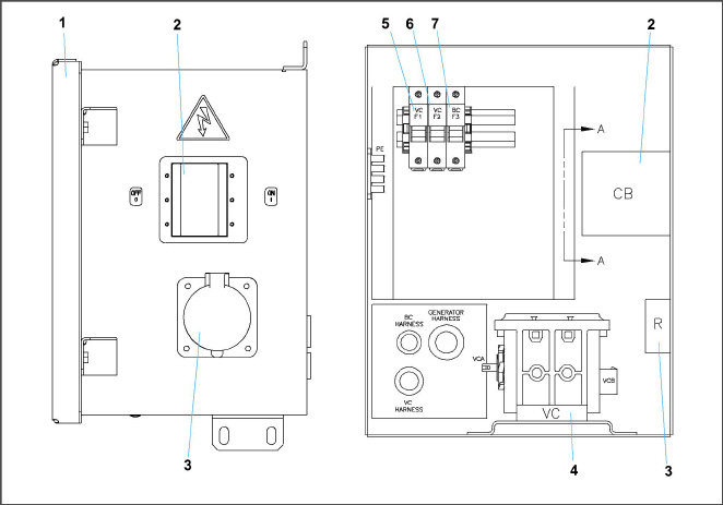
1)Access Cover
2)Circuit Breaker (CB1) Genset
3)Receptacle
4)Voltage Controller (VC)
5)Voltage Controller Fuse (VCF1)
6)Voltage Controller Fuse (VCF2)
7)Battery Charger Fuse (BCF3)
- - - - -
Safety devices, such as circuit breakers, fuses, and safety switches, protect system components from damage.
The AC generator, solid state battery charger, fuel heater, high water temperature, safety relay, total time meter and intake heater are protected by circuit breakers. If a safety device opens and there is an interruption of electrical current, the electronic governor module will be de-energized, which will also de-energize the fuel solenoid, interrupt the fuel flow to the engine and stop the engine.
Safety device specifications are provided in Table 2–1.
Engine |
||
Unsafe Condition: |
Low engine lubricating oil pressure. |
|
Safety Switch |
Low oil pressure (LOP) switch - Automatic reset |
|
Switch Setting |
Opens below 18 psig (1.27 kg/cm2) |
|
Unsafe Condition: |
High engine cooling water temperature. |
|
Safety Switch |
High water temperature (HWT) switch - Automatic reset |
|
Switch Setting |
Opens at 110°C (230°F) |
|
Unsafe Condition: |
Excessive current draw by the safety relay, fuel heater, water temperature gauge, oil pressure gauge or total time meter. |
|
Safety Switch |
Circuit breaker (CB-2) - Automatic reset |
|
Switch Setting |
Trips at 30 amps |
|
Unsafe Condition: |
Excessive current draw by the electronic governor module. |
|
Safety Switch |
Fuse 1, 2, 3 (replace) |
|
Switch Setting |
Trips at 10 amps |
|
Intake Heater |
||
Unsafe Condition: |
Excessive current draw on intake heater circuit |
|
Safety Switch |
Circuit breaker (CB-3) - Automatic reset |
|
Switch Setting |
Trips at 50 amps |
|
Battery Charger |
||
Unsafe Condition: |
Excessive current draw on 12 volt supply circuit. |
|
Safety Switch |
Circuit breaker (CB-4) - Automatic reset |
|
Switch Setting |
Trips at 50 amps |
|
Unsafe Condition: |
Excessive current draw on 460 volt feed circuit |
|
Safety Switch |
Fuse BCF3 |
|
Switch Setting |
Trips at 5 amps |
|
Generator |
||
Unsafe Condition: |
Excessive current draw by load |
|
Safety Switch |
Circuit breaker (CB-1, 460 volt) - Manual reset |
|
Switch Setting |
Trips at 26 amps (460 VAC) |
|
Voltage Controller |
||
Unsafe Condition: |
Excessive current draw on 460 volt feed circuit |
|
Safety Switch |
Fuses VCF1, VCF2 |
|
Switch Setting |
Trips at 5 amps |
|
Capacity: |
Nominal tank size: 120 gallon |
|
Fill capacity: 120 gallon |
||
Draw capacity: 119 gallon (Allows for DOT required 5% vapor space) |
||
Unit Weight: |
Engine (Dry) without accessories: 1875 lb (851 kg) approximate |
|
Output: |
15 KW, 18.75 KVA, 0.8 pf KW |
Output Voltage: |
400-500 VAC @ 60 Hz; 360-460 VAC @ 50 Hz |
Speed: |
1800 RPM @ 60 Hz; 1500 RPM @ 50 Hz |
Weight: |
267 lb (121 kg) |
Part Number: |
54-00378-20 |
Bore / Stroke: |
3.26 in (83 mm) / 4.03 in (102.4 mm) |
|
Compression Ratio: |
22.0 to 1 |
|
Cylinders (Number): |
Four |
|
Displacement: |
135.2 cubic in (2.22 liters) |
|
Firing Order: |
1-3-4-2 |
|
Screw Threads: |
All threads are metric, except for the oil drain plug which is American Standard Pipe Thread (NPT). |
|
Weight (Dry): |
439 lb (199 kg) approximate |
|
Lubrication System: |
Oil pressure: 35 to 60 psig (3.3 to 5.2 kg/cm2) |
|
|
Oil pressure safety switch setting opens: 18 psig (1.27 kg/cm2) |
|
Capacity: Engine - 15.0 US quarts (14.2 liters), includes standard filter. |
||
Oil level indicator: Dipstick in oil pan or fill cap NOTE: To check oil level on engines with the dipstick mounted in the fill cap, remove the cap and wipe the dipstick clean. Insert the cap back onto the oil fill tube, then remove to check level. It is not necessary to screw the cap back into the fill tube when checking level. DO NOT add oil if level is within the “safe” range. If needed, add oil to bring level within the “safe” range. Screw cap fully into fill tube after checking level. |
||
Lube oil specification: Use a heavy duty lubricating oil conforming to American Petroleum Institute (API) Service Classification CF or better. |
||
|
Lube oil viscosity: For outdoor temperatures 0 to 45°F (-18° to 7°C): SAE: 10W30 or Mobile Delvac 1* For outdoor temperatures above 45°F (7°C): SAE: 10W30 or 15W40 or Mobile Delvac 1* * Mobile Delvac 1, 5W-40 or 15W-40 is the only approved synthetic oil. |
|
Fuel and Fuel Heater Thermostat (FHT): |
||
|
Fuel, Winter: Diesel No. 2 with winter blends |
|
Fuel, Summer: Diesel No. 2 |
||
FHT, Winter: Close on temperature fall @ 45 + 6.5°F (7.2 + 3.6°C) |
||
FHT, Summer: Open on temperature rise @ 75 + 6.5°F (23.8 + 3.6°C) |
||
Power consumption: 150 Watts @ + 10% at 14 VDC |
||
Diesel fuel specification type and sulfur content % (ppm) used, must be compliant with all applicable emission regulations for the area in which the engine is operated. Since KUBOTA diesel engines of less than 56 kW (75 hp) utilize EPA Tier 4 and Interim Tier 4 standards, the use of ultra low sulfur fuel is mandatory for these engines, when operated in US EPA regulated areas. Therefore, please use No.2-D S15 diesel fuel. Ultra Low Sulfur Diesel (ULSD) 15 ppm or 0.0015 wt.% |
||
Intake Heater: |
Amperage - 42 amps at 12 VDC |
|
Resistance (cold) - Approx. 0.3 ohms |
||
Horsepower: |
24.8 HP @ 1800 RPM at sea level. (SAE J1995 Gross Power Rating) |
|
Cooling System: |
Capacity: 6 us quarts (5.68 liters) - includes 1 quart (0.95 liters) in coolant recovery bottle. |
|
Anti-Freeze: Extended Life The cooling system is factory charged with a 50/50 mix of extended life coolant (ELC) and deionized water. This mixture provides protection to -34°F (-37°C). For replacement, use Shell Rotella ELC Nitrite Free Pre-Diluted 50/50 antifreeze / coolant. |
||
Water temperature safety switch setting: |
||
Opens at 230 + 5°F (110 + 3°C) |
||
Resets at 200°F (93°C) - minimum |
||
Thermostat: |
||
Starts to open at 177 to 182°F (80 to 84°C) |
||
Fully open at 203°F (95°C) |
||
Low coolant sensor: |
||
Opens at loss of 32 ounces (907g) of coolant or more |
||
Closes at refilling of radiator to proper level |
||