Section 3
3.1.1Refrigeration Unit - Front Section
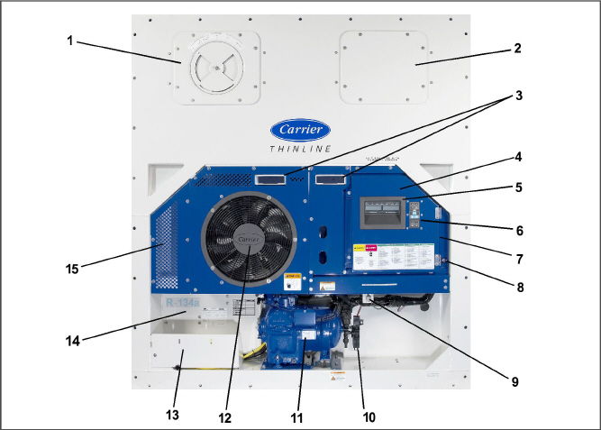
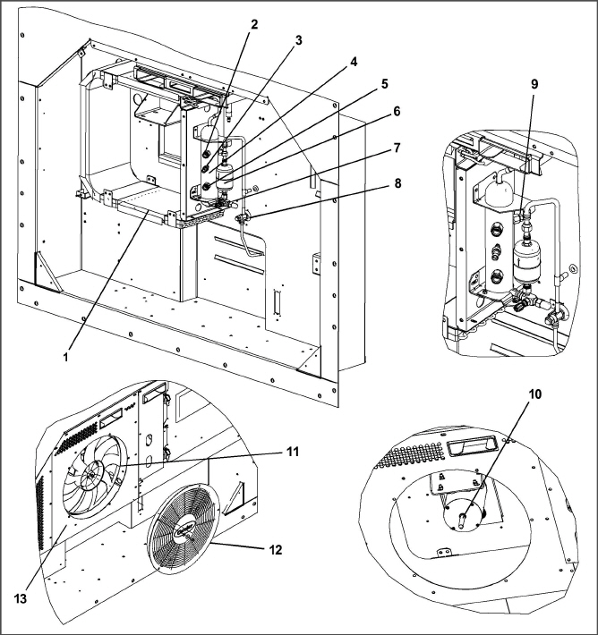
The unit is designed so the majority of the components are accessible from the front (see Figure 3.1). The unit model number, serial number, and parts identification number can be found on the serial plate to the left of the compressor.
The function of the upper or lower makeup air vent is to provide ventilation for commodities that require fresh air circulation. A manually operated venting system is located in the upper left access panel. The optional eAutoFresh vent system is to moderate the atmospheric level in the container in response to cargo respiration. When transporting frozen cargo loads the vent will be closed. The upper left access panel contains the vent slide and motor assembly. It may be removed to allow entry into the evaporator section where the CO2 sensor and drive pack are located.
Figure 3.1 Refrigeration Unit - Front Section
1. Upper Fresh Air Makeup Vent
Panel / Evap Fan #2
(Inside panel includes DTS, HS and RTS. Refer to Figure 3.2)
2. Access Panel for Evap Fan #1
(Inside panel includes TXV, TXV Bulb, and HTT. Refer to Figure 3.2)
7. Remote Monitoring Receptacle (option)
10. Supply Temperature Sensor / Supply Recorder Sensor (STS / SRS)
13. Power Cables and Plug location
14. Autotransformer location (option)
15. Lower Fresh Air Makeup Vent location
- - - - -
The evaporator section is shown below. The evaporator fans circulate air through the container by pulling it in the top of the unit, directing it through the evaporator coil where it is heated or cooled, and discharging it at the bottom.
If the unit is equipped with eAutoFresh, system components are mounted in addition to the standard refrigeration unit components. The stepper motor component is installed in the vent; the air filter, CO2 sensor, stepper motor drive and CO2 sensing lines are installed on the rib of the upper grill.
Most evaporator components are accessible by removing the upper rear panel (as shown in the illustration) or by removing the evaporator fan access panels (see Figure 3.1).
Figure 3.2 Evaporator Section - Units with Center Access Panel
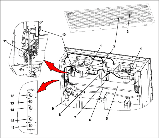
2. Return Recorder Sensor (RRS) / Return Temperature Sensor (RTS)
7. Defrost Temperature Sensor (DTS)
8. Heater Termination Thermostat (HTT)
10. Thermostatic Expansion Valve (TXV)
12. Interrogator Connector Rear (ICR)
16. Cargo Probe Receptacle PR4
- - - - -
The compressor section includes the compressor (with high pressure switch), power cable storage compartment, and autotransformer. This section also contains the quench valve, suction modulating valve, discharge pressure regulating valve, discharge temperature sensor, and discharge/suction pressure transducers. The supply temperature sensor, supply recorder sensor, and ambient sensor are located at the right side of the compressor.
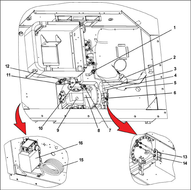
4. Quench Valve Temperature Bulb
7. Suction Pressure Transducer
9. Compressor Sight Glass View Port
10. Discharge Pressure Transducer
13. Supply Temperature Sensor (STS)
14. Supply Recorder Sensor (SRS)
- - - - -
3.1.5Air-Cooled Condenser Section
The air-cooled condenser section (Figure 3.4) consists of the condenser fan, condenser coil, receiver with sight glass/moisture indicator, quench valve, liquid line service valve, filter-drier, condenser pressure transducer, and fusible plug. The condenser fan pulls air from around the coil and discharges it horizontally through the condenser fan grille.
3. Condenser Pressure Transducer
5. Sight Glass/Moisture Indicator
- - - - -
The control box (Figure 3.5) includes the manual operation switches, circuit breaker (CB-1), compressor, fan and heater contactors, control power transformer, current sensor module, controller module and the communications interface module.
3.1.7Communications Interface Module (option)
The communications interface module is a slave module which allows communication between the refrigeration unit and a ship system master central monitoring station. The module will respond to communication, and return information over the ships main power line. Refer to the master system technical manual for further information.
Figure 3.5 Control Box Section
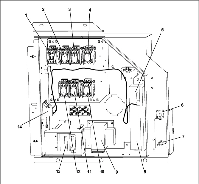
2. Compressor Phase A Contactor - PA
3. Compressor Phase B Contactor - PB
5. Controller / DataCORDER Module (Controller)
6. Remote Monitoring Receptacle
8. Controller Battery Pack (Standard Location)
10. High Speed Evaporator Fan Contactor - EF
11. Low Speed Evaporator Fan Contactor - ES
12. Condenser Fan Contactor - CF
13. Circuit Breaker (CB1) - 460V
- - - - -
* Rupture Disc, part number 14-00215-04 may be installed as an alternate for the receiver mounted fusible plug.
3.4Safety and Protective Devices
Unit components are protected from damage by safety and protective devices listed in the following table. These devices monitor the unit operating conditions and open a set of electrical contacts when an unsafe condition occurs.
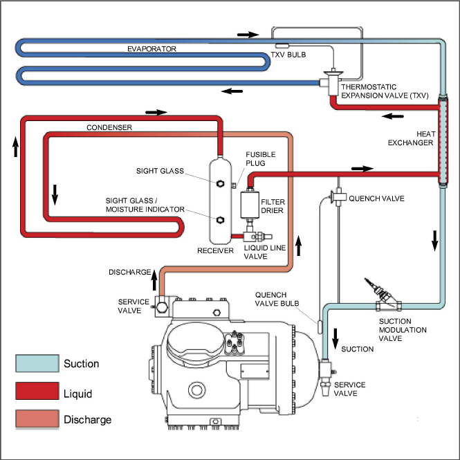
Starting at the compressor (see Figure 3.6), the suction gas is compressed to a higher pressure and temperature.
The gas flows out the compressor through the discharge service valve. Refrigerant gas then moves into the air-cooled condenser, where air flowing across the coil fins and tubes cools the gas to saturation temperature. By removing latent heat, the gas condenses to a high pressure/high temperature liquid and flows to the receiver, which stores the additional charge necessary for low temperature operation.
The liquid refrigerant continues through the liquid line service valve, the filter-drier (which keeps refrigerant clean and dry), and a heat exchanger (that increases sub-cooling of the liquid) to the thermostatic expansion valve (TXV).
As the liquid refrigerant passes through the variable orifice of the TXV, the pressure drops to suction pressure. In this process some of the liquid vaporizes to a gas (flash gas), removing heat from the remaining liquid. The liquid exits as a low pressure, low temperature, saturated mix. Heat is then absorbed from the return air by the balance of the liquid, causing it to vaporize in the evaporator coil. The vapor then flows through the suction tube back to the compressor.
The TXV is activated by the bulb strapped to the suction line near the evaporator outlet. The valve maintains a constant superheat at the coil outlet regardless of load conditions.
The TXV is a mechanical device that regulates the flow of liquid to the evaporator coil in order to maintain a relatively constant degree of superheat in the gas leaving the evaporator regardless of suction pressure.
The flow of liquid to the evaporator is regulated by a variable orifice which opens to increase refrigerant flow (decrease superheat), or closes to decrease refrigerant flow (increase superheat). The variable orifice is controlled by the temperature sensing bulb which is strapped to the suction line near the evaporator outlet.
During periods of low load, the suction modulating valve (SMV) decreases flow of refrigerant to the compressor. This action balances the compressor capacity with the load and prevents operation with low coil temperatures. In this mode of operation, the quench valve will open as required to provide sufficient liquid refrigerant flow into the suction line for cooling of the compressor motor. The quench valve senses refrigerant condition entering the compressor and modulates the flow to prevent entrance of liquid into the compressor.
The refrigeration system is also fitted with a condenser pressure transducer, which feeds information to the controller. The controller programming will operate the condenser fan so as to attempt to maintain discharge pressures above 130psig in low ambients. At ambients below 27°C (80°F), the condenser fan will cycle on and off depending on condenser pressure and operating times.
1.The condenser fan will start if the condenser pressure is greater than 200 psig OR the condenser fan has been OFF for more than 60 seconds.
2.The condenser fan will stop if the condenser pressure is less than 130 psig AND the condenser fan has been running for at least 30 seconds.
At ambients above 27°C (80°F), condenser pressure control is disabled and the condenser fan runs continuously.
Figure 3.6 Refrigeration Circuit with Receiver