Section 5
Beware of unannounced starting of the evaporator and condenser fans. The unit may cycle the fans and compress or unexpectedly as control requirements dictate.
1.Check inside the unit for the following conditions:
•Check channels or “T” bar floor for cleanliness. Channels must be free of debris for proper air circulation.
•Check container panels, insulation and door seals for damage. Perform permanent or temporary repairs.
•Check visually that the evaporator fan motor mounting bolts are properly secured (see Section 7.17).
•Check for visible corrosion on the evaporator stator and fan deck (see Section 7.18).
•Check for dirt or grease on evaporator fans or fan deck and clean if necessary (see Section 7.18).
•Check evaporator coil for cleanliness or obstructions. Wash with fresh water (see Section 7.18).
•Check defrost drain pans and drain lines for obstructions and clear if necessary. Wash with fresh water.
•Check panels on refrigeration unit for loose bolts and condition of panels. Make sure T.I.R. devices are in place on access panels.
2.Check condenser coil for cleanliness. Wash with fresh water (see Section 7.11).
3.Open the control box door. Check for loose electrical connections or hardware.
4.Check color of moisture-liquid indicator.
Do not attempt to remove power plug(s) before turning OFF the Start-Stop switch (ST), unit circuit breaker(s) and external power source.
Make sure the power plugs are clean and dry before connecting to power receptacle.
5.2.1Connecting to 380/460 VAC Power
1.Make sure the Start-Stop switch (ST), located on the control panel, is in “0” position (Off).
2.Make sure circuit breaker CB-1, located in the control box, is in “0” position (Off).
3.Plug the 460 VAC (yellow) cable into a de-energized 380/460 VAC, 3-phase power source and energize the power source.
4.Place circuit breaker CB-1 in “I” position (On).
5.Close and secure the control box door.
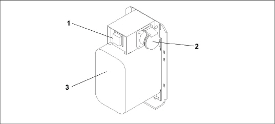
5.2.2Connecting to 190/230 VAC Power
To allow unit operation on nominal 230 volt power, an autotransformer (see Figure 5.1) is required. The autotransformer is fitted with a 230 VAC cable and a receptacle to accept the standard 460 VAC power plug. The 230 volt cable is black in color while the 460 volt cable is yellow. The transformer may also be equipped with a circuit breaker (CB-2). The transformer is a step-up transformer that provides 380/460 VAC, 3-phase, 50/60 Hz power to the unit when the 230 VAC power cable is connected to a 190/230 VAC, 3-phase power source.
PROCEDURE:
1.Make sure the Start-Stop switch (ST), located on the control panel, is in “0” position (Off).
2.Make sure circuit breaker CB-1, located in the control box, and CB-2, located on the transformer, are both in “0” position (Off).
3.Plug in and lock the 460 VAC power plug at the receptacle on the transformer.
4.Plug the 230 VAC (black) cable into a de-energized 190/230 VAC, 3-phase power source and energize the power source.
5.Set circuit breakers CB-1 and CB-2 to “I” position (On).
6.Close and secure the control box door.
1)Circuit Breaker (CB-2) 230-Volt
2)460 VAC Power Receptacle
3)Dual Voltage Module Autotransformer
- - - - -
5.3Adjust Fresh Air Makeup Vent
The purpose of the fresh air makeup vent is to provide ventilation for commodities that require fresh air circulation. The vent must be closed when transporting frozen foods.
Air exchange depends on static pressure differential, which will vary depending on the container and how the container is loaded.
Units may be equipped with a vent position sensor (VPS). The VPS determines the position of the fresh air vent (upper or lower, as equipped) and sends data to the controller display.
5.3.1Upper Fresh Air Makeup Vent
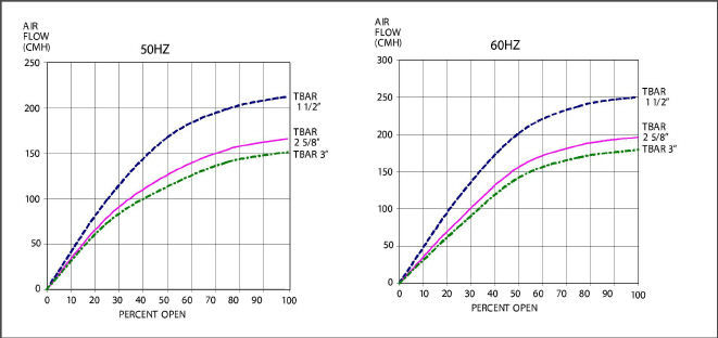
Two slots and a stop are designed into the Upper Fresh Air disc for air flow adjustments. The first slot allows for a 0 to 30% air flow; the second slot allows for a 30 to 100% air flow.
To adjust the percentage of air flow, loosen the wing nut and rotate the disc until the desired percentage of air flow matches with the arrow. Tighten the wing nut.
To clear the gap between the slots, loosen the wing nut until the disc clears the stop.
See Figure 5.2 for air exchange values for an empty container. Higher values can be expected for a fully loaded container.
Figure 5.2 Upper Fresh Air Make Up Flow Chart
5.3.2Lower Fresh Air Makeup Vent
a. Full Open or Closed Positions
Maximum air flow is achieved by loosening the wing nuts and moving the cover to the maximum open (100%) position. The closed position is 0% air flow position. The operator may also adjust the opening to increase or decrease the air flow volume to meet the required air flow.
b. Reduced Flow for Lower Fresh Air Makeup
In order to prevent inaccurate display readings on units equipped with a VPS, ensure that the rack and pinion drive of the VPS is not disrupted when adjusting the air makeup vent.
Do not loosen the hex nut beyond its stop. Doing so may cause inaccurate display readings and errors in DataCORDER reports.
Similar to the Upper Fresh Air Makeup vent, two slots and a stop are designed into the Lower Fresh Air slide for air flow adjustments. The first slot allows for a 0 to 25% air flow; the second slot allows for a 25 to 100% air flow. To adjust the percentage of air flow, loosen the hex nut and rotate the disc until the desired percentage of air flow matches with the arrow. Tighten the hex nut. To clear the gap between the slots, loosen the hex nut until the disc clears the stop.
On some models the air slide is supplied with two adjustable air control discs. The fresh air makeup can be adjusted for 15, 35, 50 or 75 cubic meters per hour (CMH). The air flow has been established at 60 Hz power and 2-1/2 inch T bar and with 15 mm (0.6 inch) H2O external static above free blow.
Loosen the hex nut, adjust each disc to the required air flow, then tighten the hex nut.
The main air slide is in the fully closed position during reduced air flow operation when equipped with air control discs.
c. Air Sampling for Carbon Dioxide (CO2) Level
Loosen the hex nuts and move the cover until the arrow on the cover is aligned with the “atmosphere sampling port” label. Tighten the hex nuts and attach a 3/8 in. hose to the sampling port.
If the internal atmosphere content has reached an unacceptable level, the operator may adjust the disc opening to meet the required air flow volume to ventilate the container.
The vent position sensor (VPS) allows the user to determine the position of the fresh air vent via Cd45. This function code is accessible via the Code Select key.
The vent position will display for 30 seconds whenever motion corresponding to 5 CMH (3 CFM) or greater is detected. It will scroll in intervals of 5 CMH (3 CFM). Scrolling to Cd45 will display the Fresh Air Vent Position.
The position of the vent will be recorded in the DataCORDER whenever the unit is running under AC power and during any of the following conditions:
•Trip start
•Every power cycle
•Midnight
•Manual changes greater than 5 CMH (3 CFM) remaining in the new position for at least four minutes
The user has four minutes to make necessary adjustments to the vent setting. This time calculation begins on the initial movement of the sensor. The vent can be moved to any position within the four minutes. On completion of the first four minutes, the vent is required to remain stable for the next four minutes. If vent position changes are detected during the four-minute stability period, AL50 will be generated. This provides the user with the ability to change the vent setting without generating multiple events in the DataCORDER.
The optional eAutoFresh™ venting system is controlled through two function codes, Code 43 and Code 44. Code 43 contains specific parameters for operation and Code 44 provides a visible display of component conditions.
Procedures and technical information related to the eAutoFresh™ venting system can be found in the T-342 eAutoFresh Manual, located in the Literature section of the Container Refrigeration website. To find the manual from the Literature section, click on Options > eAutoFresh.
The optional XtendFRESH™ controlled atmosphere system is controlled through two function codes, Code 43 and Code 44. Code 43 contains specific parameters for operation and Code 44 provides a visible display of component conditions.
Procedures and technical information related to the XtendFRESH™ controlled atmosphere system can be found in the T-366 XtendFRESH Manual, located in the Literature section of the Container Refrigeration website. To find the manual from the Literature section, click on Options > XtendFRESH.
5.6Connect Water-Cooled Condenser
The water-cooled condenser is used when cooling water is available and heating the surrounding air is objectionable, such as in a ship’s hold. If water-cooled operation is desired, connect in accordance with the following subparagraphs.
5.6.1Water-Cooled Condenser with Water Pressure Switch
1.Connect the water supply line to the inlet side of the condenser and the discharge line to the outlet side of the condenser (see Figure 3.6, Figure 3.7).
2.Maintain a flow rate of 11 to 26 liters per minute (3 to 7 gallons per minute). The water pressure switch will open to de-energize the condenser fan relay. The condenser fan motor will stop and will remain stopped until the water pressure switch closes.
3.To shift to air-cooled condenser operation, disconnect the water supply and the discharge line to the watercooled condenser. The refrigeration unit will shift to air-cooled condenser operation when the water pressure switch closes.
5.6.2Water-Cooled Condenser with Condenser Fan Switch
1.Connect the water supply line to the inlet side of condenser and the discharge line to the outlet side of the condenser (see Figure 3.6, Figure 3.7).
2.Maintain a flow rate of 11 to 26 lpm (3 to 7 gpm).
3.Set the condenser fan switch to position “O.” This will de-energize the condenser fan relay. The condenser fan motor will stop and remain stopped until the CFS switch is set to position “I.”
When condenser water flow is below 11 lpm (3 gpm) or when water-cooled operation is not in use, the CFS switch MUST be set to position “1” or the unit will not operate properly.
4.To shift to air-cooled condenser operation, stop the unit, set the CFS switch to position “I” and restart the unit. Disconnect the water lines to the water-cooled condenser
5.7Connect Remote Monitoring Receptacle
If remote monitoring is required, connect the remote monitor plug at the unit receptacle (see Figure 3.8).
When the remote monitor plug is connected to the remote monitoring receptacle, the following remote circuits are energized:
Circuit |
Function |
|---|---|
Sockets B to A |
Energizes remote cool light |
Sockets C to A |
Energizes remote defrost light |
Sockets D to A |
Energizes remote in-range light |
5.8Starting and Stopping Instructions
Make sure that the unit circuit breaker(s) CB-1 & CB-2 and the Start-Stop switch (ST) are in the “O” (OFF) position before connecting to any electrical power source.
The electronic phase detection system will check for proper compressor rotation within the first 30 seconds. If rotation is not correct, the compressor will be stopped and restarted in the opposite direction. If the compressor is producing unusually loud and continuous noise after the first 30 seconds of operation, stop the unit and investigate.
1.Verify that power is properly applied, the fresh air vent is in proper position, and (if required) the water-cooled condenser is connected.
2.Place the Start-Stop switch (ST) to position “I” (ON) (see Figure 3.8). The controller function codes for the container ID (Cd40), software version (Cd18) and unit model number (Cd20) will be displayed in sequence.
3.Continue with the Start Up Inspection. See Section 5.9.
1.To stop the unit, place the Start-Stop switch (ST) in position “0” (OFF).
Check rotation of condenser and evaporator fans.
5.9.2Check Controller Function Codes
Check, and if required, reset controller Function Codes (Cd27 through Cd39) in accordance with desired operating parameters. See Table 4–6.
5.9.3Start Temperature Recorder
1.Check and, if required, set the DataCORDER Configuration in accordance with desired recording parameter. See Section 4.7.3.
2.Enter a “Trip Start” with the following instructions:
a.Press the ALT MODE key. When the left display shows “dC”, press the ENTER key.
b.Scroll to Code dC30.
c.Press and hold the ENTER key for five seconds.
d.The “Trip Start” event will be entered in the DataCORDER.
Allow the unit to run for five minutes to stabilize conditions, and then perform a pre-trip diagnosis in accordance with Section 5.10.
Pre-trip inspection should not be performed with critical temperature cargoes in the container.
When PRE-TRIP key is pressed, economy, dehumidification and bulb mode will be deactivated. At the completion of pre-trip activity, economy, dehumidification and bulb mode must be reactivated.
Pre-trip diagnosis provides automatic testing of the unit components using internal measurements and comparison logic. The program will provide a “PASS” or “FAIL” display to indicate test results.
The testing begins with access to a pre-trip selection menu. The user may have the option of selecting one of two automatic tests. These tests will automatically perform a series of individual pre-trip tests. The user may also scroll down to select any of the individual tests.
When only the short sequence is configured, it will appear as “AUtO” in the display. Otherwise “AUtO1” will indicate the short sequence and “AUtO2” will indicate the long sequence. The test short sequence will run tests P0 through P6. The long test sequence will run tests P0 through P10.
A detailed description of the pre-trip test codes is listed in Table 4–7. If no selection is made, the pre-trip menu selection process will terminate automatically. However, dehumidification and bulb mode must be reactivated manually if required.
Scrolling down to the “rSLts” code and pressing ENTER will allow the user to scroll through the results of the last pre-trip testing run. If no Pre-testing has been run (or an individual test has not been run) since the unit was powered up, “- - - -” will be displayed.
Pre-trip may also be initiated via communications. The operation is the same as for the keypad initiation described below except that should a test fail, the pre-trip mode will automatically terminate. When initiated via communications, a pre-trip test may not be interrupted with an Arrow key, but the pre-trip test can be terminated with the PRE-TRIP key.
5.10.1Prior to Starting a Pre-Trip
Verify the following conditions prior to starting a pre-trip.
•Unit voltage (Cd07) is within tolerance.
•Unit amperage draw (Cd04, Cd05, Cd06) are within expected limits.
•All alarms are cleared and rectified.
1.Press the PRE-TRIP key to access the pre-trip test selection menu.
2.To Run an Automatic Test: Scroll through the selections by pressing the Up or Down Arrow keys to display AUTO, AUTO 1, AUTO 2 or AUTO 3 as desired, then press the ENTER key.
•The unit will execute the series of tests without any need for direct user interface. These tests vary in length, depending on the component under test.
•While tests are running, “P#-#” will appear on the left display; the #’s indicate the test number and sub-test. The right display will show a countdown time in minutes and seconds, indicating the amount of time remaining in the test.
When a Pre-trip Auto 1 test runs to completion without a failure, the unit will exit pre-trip mode and return to normal control operation. However, dehumidification and bulb mode must be reactivated manually if required.
When a Pre-trip Auto 2 test runs to completion without being interrupted, the unit will terminate Pre-trip and display “Auto 2” “end.” The unit will suspend operation until the user depresses the ENTER key!
3.When an automatic test fails, it will be repeated once. A repeated test failure will cause “FAIL” to be shown on the right display, with the corresponding test number to the left. Press the Down Arrow key to repeat the test, the Up Arrow key to skip to the next test, or the PRE-TRIP key to terminate testing. The unit will wait indefinitely or until a command is entered.
When a failure occurs during automatic testing, the unit will suspend operation awaiting operator intervention.
4.To Run an Individual Test: Scroll through the selections by pressing the Up or Down Arrow keys to display an individual test code. Press the ENTER key when the desired test code is displayed.
•Individually selected tests, other than the LED / Display test, will perform the operations necessary to verify the operation of the component. At the conclusion, “PASS” or “FAIL” will be displayed. This message will remain displayed for up to three minutes, during which time a user may select another test. If the three minute time period expires, the unit will terminate Pre-trip and return to control mode operation.
•While the tests are being executed, the user may terminate the Pre-trip diagnostics by pressing and holding the PRE-TRIP key. The unit will then resume normal operation. If the user decides to terminate a test but remain at the test selection menu, the user may press the Up Arrow key. When this is done, all test outputs will be de-energized and the test selection menu will be displayed.
•Throughout the duration of any Pre-trip test (except during P-7 high pressure switch tests), the current limiting and pressure limiting processes are both active. The current limiting process is only active for P-7.
5.10.3Displaying Pre-Trip Test Results
1.Press the PRE-TRIP key to access the Pre-trip test selection menu. “SELCt Prtrp” will be displayed.
2.Press the Arrow keys until the message “P,” “rSLts” (Pre-trip results) is displayed.
3.Press the ENTER key. The results for all Pre-trip sub tests are available from this menu (i.e., 1-0, 1-1, etc).
The results will be displayed as “PASS” or “FAIL” for all the tests run to completion since power up. If a test has not been run since power up, “- - - - -” will be displayed.
Once all Pre-test activity is completed, dehumidification and bulb mode must be reactivated manually if required.
A complete temperature probe check is performed during the P5 pre-trip test. A probe check is also run at the end of a defrost cycle; the defrost light will remain on during this period. If supply probes are within limits and return probes are within limits, the unit will return to normal operation. During normal operation, the controller continuously monitors and compares adjacent temperature probe readings.
The probe check procedure consists of running the evaporator fans for up to eight minutes in order to compare the readings from the adjacent temperature probes. If a significant difference in temperature readings is detected between probes, a defrost cycle, followed by another probe check may be initiated. Any continued disagreement between probes will prompt the controller to invalidate the failed temperature probe, and the backup probe will be used for temperature control.
In Perishable Mode, both pairs of supply and return probes are monitored for probe disagreement. Probe disagreement is considered a difference of 0.5°C (0.9°F) or greater between the supply air sensors and/ or a difference of 2.0°C (3.6°F) between the return air sensors. Probe disagreement found in either pair can trigger a defrost probe check.
In Frozen Mode, only the controlling probes are considered. Disagreement of the controlling probes can trigger a defrost probe check, which will occur when the difference between the sensors is greater than 2.0°C (3.6°F). Normally, the controlling probes are the return probes but if both return probes are invalidated, the supply probes are used for control purposes. Probe disagreement of the non-controlling probe pair will not trigger a defrost probe check.
If after the defrost probe check the supply probes agree and return probes agree, all supply and return sensors are considered valid and the unit returns to normal control.
In the Case of Probe Disagreement:
If the supply probes disagree and the return probes agree, the controller will invalidate the worst supply probe. If the probe check is run as part of pre-trip P-5, an alarm will be triggered for the invalidated probe. If it is a run time defrost probe check, the invalidated probe will be passed over and no alarm will be triggered. However, if the best supply probe is greater than 1.2°C (2.2°F) difference with respect to its return probes, the best supply probe is also invalidated. If unit is in Perishable Mode, a probe alarm will be triggered for both supply probes.
If the supply probes agree and the return probes disagree, invalidate the worst return probe. If the probe check is being run as part of pre-trip P-5, an alarm will be triggered for the invalidated probe. If it is a run time defrost probe check, the invalidated probe will be passed over and no alarm will be necessary. If the best return probe is greater than 1.2°C (2.2°F) difference with respect to its supply probes, then the best return probe is also invalidated. If the unit is in perishable mode, a probe alarm will be triggered for both return probes.
5.12Emergency Bypass Operation (Option)
Emergency Bypass operation is used to override the controller, in the case of a controller malfunction, to keep the unit cooling. When Emergency Bypass is installed and turned on, the unit will remain in a continuous state of full cool until the Emergency Bypass switch is turned off.
To place the unit in the Emergency Bypass Operation:
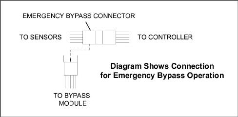
1.Locate the connection diagram and connectors for the emergency bypass (EB) sensors behind the top left side of the compressor.
2.Disconnect the emergency bypass connector from the controller connector and attach it to the emergency bypass module connector (See Figure 5.3).
3.Locate the wire tire located at the EB switch in the control box.
4.Cut the wire tie, then place the EB switch in the On position.
5.Place the Mode Switch (MS) in the Full Cool position to enable the system for cooling.
6.Manually control container air temperature by cycling the Mode switch between Full Cool and evaporator Fans Only.
To operate the fans only, the MODE switch must be in the Fans Only position and the EMERGENCY BYPASS switch must be in the Bypass position.
The EBS module uses the system’s safety devices (high pressure switch, motor internal protectors, and heat termination thermostat) to protect the system while in Emergency Bypass Mode.
The unit will remain in the full cooling mode as long as the EB switch is in the On position and the Mode Switch is in the Full Cool position. If the cargo can be damaged by low temperatures, the operator must monitor container temperature and manually cycle operation as required to maintain temperature within required limits.
When the Emergency Bypass switch is in the Bypass position, the EBS will be enabled.
With the Mode switch in Full Cool mode, the following will occur simultaneously:
a.The EBS switch will enable EBS input.
b.The phase detection circuit will detect the phase rotation and close to provide power to the compressor contactor.
c.The condenser fan contact will close to energize the condenser contactor and provide power to the condenser fan motor.
d.The evaporator fan contact will close to energize the high speed evaporator contactor and provide power to the evaporator fan motor.
e.The EBS electronic module will operate the EEV to control superheat.
To return the unit to normal operation:
1.Locate the connectors behind the compressor.
2.Disconnect the Emergency Bypass connector from the EBS module connector and reconnect it to the controller connector (see Figure 5.3).
3.Inside the control box, place the EB switch in the Off position.
4.Re-install the wire tie at the switch mounting.
Figure 5.3 Diagram of Emergency Bypass Connections
TripWiseTM is a new premium option available for PrimeLINE and PrimeLINE with Edge units. TripWise is software logic that runs during every voyage as often as possible to indicate whether a standard Pre-trip Inspection (PTI) is needed and skip unless necessary. The tests run in the background and are similar to those completed as part of the standard PTI selection, which includes the following:
•Alarm Presence
•Evaporator Motor Current
•Heater Current
•Condenser Motor Current
•Compressor Current
•Humidity Sensor
•Supply / Return Sensors
•Evaporator Temperature and Pressure Sensors
•Defrost Temperature Sensor
•Electronic Expansion Valve
•RMU Presence
•Compressor Test
•Digital Loader / Unloader Valves
•Economizer Valve
•Temperature Control
•Suction / Discharge Temperature and Pressure
5.13.1Checking TripWise Status
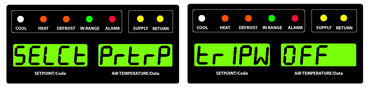
To check the status of the container, press the PRE-TRIP key on the keypad. The message “SELCt | PrtrP” will appear on the display module, alternating with one of the following TripWise status messages:
•trIPW | OFF. The TripWise option is turned off.
•trIPW | EX (Expired). It is recommended to pre-trip the unit prior to the unit's next trip following customer-specific guidelines.
• trIPW | PASS. The container should be ready for use after the operator has conducted a visual inspection. Standard PTI is not required.
•trIPW | CHECK. If any TripWise test(s) execute and do not meet the pass / fail requirements, It is recommended to pre-trip the unit following customer-specific guidelines prior to the unit's next trip.
Pressing the ENTER key while “SELCt | PrtrP” is displayed will enter into the Pre-trip test menu. Pressing the Arrow keys will navigate through the standard PTI test selections menu.
5.13.2Enabling or Disabling TripWise Option
1.Press the CODE SELECT key on the keypad.
2.Use the Arrow keys to bring up code Cd65 in the display.
3.Press the ENTER key. The display will show either “-----”, “OFF” or “ON”.
If “-----” is displayed, the TripWise function option is not active on the unit. To add this option to the unit, the equipment owner would need to contact their Regional Carrier Sales Manager.
4.Use the Arrow keys to toggle between “ON” and “OFF” and then press the ENTER key to select the desired option.
5.If “ON” is selected, the display will show “dAYS”. This is the expiration time (2 through 365 in 1 day increments). Use the Arrow keys to change the parameter and then press the ENTER key to confirm.
The expiration interval is the total maximum days allowed between the running of each test. For example, if days are set to 30 and the low speed evaporator fan test has not run within those 30 days, the TripWise expired message will be displayed. If the TripWise expired message is displayed, it is recommended to Pre-trip the unit following customer specific guidelines prior to the next trip.
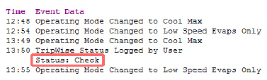
A TripWise status event will be recorded in the DataCorder recorder when the PTI is selected. In the current DataLINE software release, the event will show the status of the unit.
Figure 5.4 TripWise Status in DataCorder
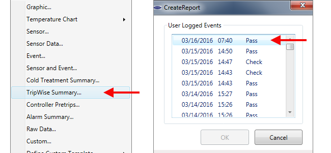
In DataLINE version 3.2, perform an all data download by selecting from the drop down menu “TripWise Summary” and then select a date in “User Logged Events” as shown in the Figure below.
Figure 5.5 Generating TripWise Summary Report
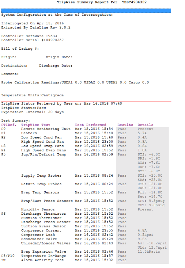
This will generate the status / results in a DataLINE TripWise Summary Report as shown in the Figure below.
Figure 5.6 TripWise Summary Report
5.14Automatic Cold Treatment (Option)
Cold Treatment has been employed as an effective post-harvest method for the control of Mediterranean and certain other tropical fruit flies. Exposing infested fruit to temperatures of 2.2°C (3.6°F) or below for specific time periods results in the mortality of various life stages for this group of insects.
Automated Cold Treatment (ACT) in the Carrier Transicold unit is a method to simplify the task of completing cold treatment by automating the process of changing the setpoints. ACT is set up through function code Cd51. Refer to Function Code table in this manual for Cd51 menu processing and displays.
ACT, setup with Cd51, and Automatic Setpoint Change (ASC), setup with Cd53, will not work simultaneously. Setting one will deactivate the other.
Procedure to Set ACT:
1.Enter the required cargo setpoint. It must be lower than the treatment temperature discussed in step 5.
2.Press the CODE SELECT key.
3.Use the Arrow keys to scroll to Cd51, and then press the ENTER key.
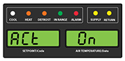
4."ACt" is now displayed in the left display and the right will display "Off". Use the Arrow keys to bring up "On" in the right display and press the ENTER key.
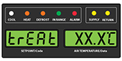
5.“trEAt" is now displayed in the left display and the right will be flashing the last setting (shown as XX.X°C). Use the Arrow keys to select the desired cold treatment setpoint and press the ENTER key.
"trEAt" is the maximum value that the USDA probes need to remain below, to pass the Cold Treatment protocol. For instance, if the treat value is set at 35.0°F (1.7°C) then the USDA probe temperatures must remain below 35.0°F (1.7°C) to pass.
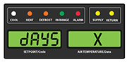
6."dAyS" is now displayed in the left display and the right will be flashing. Use the Arrow keys to select the desired days for cold treatment and press the ENTER key.
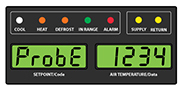
7."ProbE" is now displayed in the left display and the right will display the probe numbers that are connected. Press the ENTER key. For instance, if "1234" is displayed, then all four of the probes are connected.
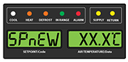
8."SPnEW" is now displayed in the left display and the right will be flashing. Use the Arrow keys to select the desired setpoint after the cold treatment process has successfully completed and press the ENTER key. This would be the final temperature prior to the delivery of the cargo.
9.Cd51 is now displayed in the left display and the right will display days / hours remaining in cold treatment.
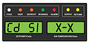
10.The unit will start to countdown once all detected USDA probes have reached the specified cold treatment temperature. The cold treatment process will continue until the specified number of days is reached. During operation, Cd51 will show the number of days and hours remaining in the cold treatment.
Once the cold treatment process has been initiated, setpoint change via the keypad is disabled.
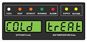
11.While the unit is operating in ACT mode, the left hand display will alternate between "COLd" and setpoint. The right hand display will alternate between "trEAt" and the cargo temperature. Once the treatment time has been completed, the setpoint temperature will increase to the "SPnEW" setting chosen in step 8.
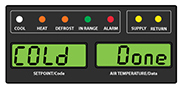
12.When the cold treatment process is complete, the "SPnEW" setpoint will be displayed in the left hand display and cargo temperature in the right hand display, alternating with "COLd" "Done". "COLd" "Done" will continue to alternate with the setpoint and cargo temperature until ACT is turned off.
Procedure to Turn ACT OFF:
ACT will be automatically turned off with a TripStart, or if a Pretrip is initiated.
1.To manually turn ACT Off, press the CODE SELECT key.
2.Use the Arrow keys to scroll to Cd51, and then press the ENTER key.
3.Use the Arrow keys to bring up "Off" in the right display and press the ENTER key.