Section 3
3.1.1Refrigeration Unit - Front Section
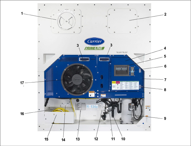
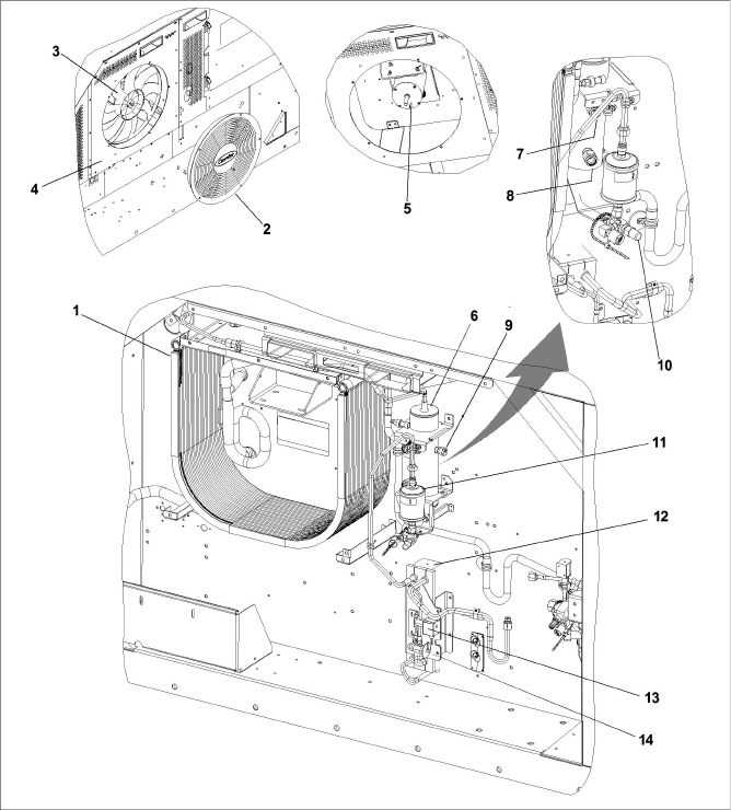
The unit is designed so that the majority of the components are accessible from the front (see Figure 3.1). The unit model number, serial number and parts identification number can be found on the unit nameplate on the back wall under the condenser fan.
Figure 3.1 Refrigeration Unit - Front Section
1)Upper Fresh Air Makeup Vent Panel. Located inside are: Evaporator Fan #2, Defrost Temperature Sensor (DTS)
2)Access Panel. Located inside are: Evaporator Fan #1, Electronic Expansion Valve (EEV), Heat Termination Thermostat (HTT)
7)Remote Monitoring Receptacle (if equipped)
10)Access Panel for Supply Temperature Sensor (STS) / Supply Recorder Sensor (SRS)
11)Ambient Temperature Sensor (AMBS)
16)Autotransformer location (if equipped)
- - - - -
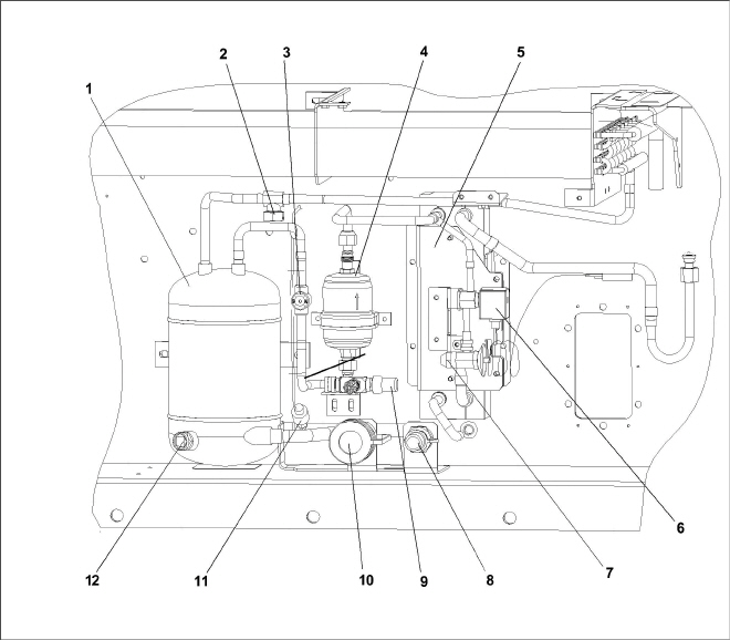
The compressor section (see Figure 3.2) includes the compressor, digital unloader valve (DUV), high pressure switch, discharge pressure transducer (DPT), evaporator pressure transducer (EPT) and the suction pressure transducer (SPT). The supply temperature sensor (STS) and supply recorder sensor (SRS) are located to the left of the compressor.
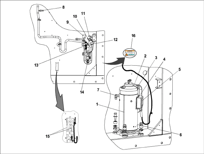
2)Compressor Discharge Temperature Sensor (CPDS) location
8)Discharge Pressure Transducer (DPT)
9)Digital Unloader Valve (DUV)
10)Suction Pressure Transducer (SPT)
11)Evaporator Pressure Transducer (EPT)
15)Supply Temperature Sensor (STS) / Supply Recorder Sensor (SRS)
- - - - -
3.1.3Air-Cooled Condenser Section
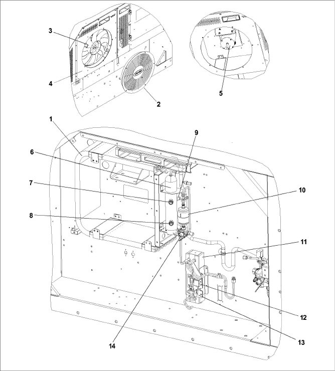
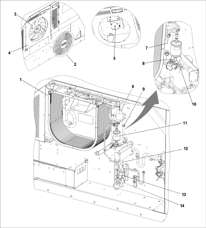
The air-cooled condenser section (see Figure 3.3) consists of the condenser fan, condenser coil, receiver, liquid line service valve, filter drier, fusible plug, economizer, economizer expansion valve (EXV), economizer solenoid valve (ESV), and sight glass / moisture indicator. The condenser fan pulls air from around the coil and discharges it horizontally through the condenser fan grille.
Figure 3.3 Condenser Section with “C” Shape Coil (PIDs < NT3000)
8)Receiver Moisture & Liquid Indicator
12)Economizer Solenoid Valve (ESV)
13)Economizer Expansion Valve (EXV)
- - - - -
Figure 3.4 Condenser Section, with MCHE and Steel Receiver (PIDs NT3000 to NT3099)
8)Receiver Moisture & Liquid Indicator
13)Economizer Solenoid Valve (ESV)
14)Economizer Expansion Valve (EXV)
- - - - -
Figure 3.5 Condenser Section, with MCHE and Aluminum Receiver (PIDs > NT3100)
8)Receiver Moisture & Liquid Indicator
13)Economizer Solenoid Valve (ESV)
14)Economizer Expansion Valve (EXV)
- - - - -
3.1.4Water-Cooled Condenser Section
The unit may contain a water-cooled condenser (WCC) installed as an option. When operating on the water-cooled condenser, the condenser fan is deactivated by a water pressure switch or condenser fan switch. There are two types of water-cooled condensers available and both are described below.
Tube in Shell Water-Cooled Condenser
The tube in shell water-cooled condenser section (see Figure 3.6) consists of a water-cooled condenser, sight glass, rupture disc, filter drier, water couplings, water pressure switch, economizer, economizer expansion valve (EXV), economizer solenoid valve (ESV), and moisture / liquid indicator. The water-cooled condenser is in series with the air-cooled condenser and replaces the standard unit receiver.
Figure 3.6 Tube In Shell Water-Cooled Condenser
1)Water-Cooled Condenser (WCC)
6)Economizer Solenoid Valve (ESV)
7)Economizer Expansion Valve (EXV)
9)Liquid Line Service Valve / Connection
10)Self Draining Coupling - Water Out
11)Water Pressure Switch (WPS)
- - - - -
Brazed Plate Water-Cooled Condenser
The brazed plate water-cooled condenser section (see Figure 3.7) consists of the brazed plate water-cooled condenser (WCC), water couplings, a water pressure switch and a fusible plug. The receiver is retained in this configuration and the brazed plate heat exchanger is placed between the air-cooled condenser and the receiver.
Figure 3.7 Brazed Plate Water-Cooled Condenser
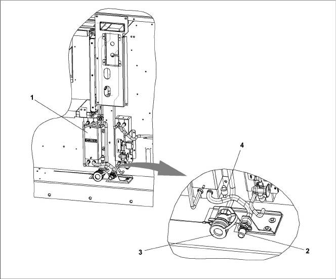
1)Water-Cooled Condenser (WCC)
3)Self Draining Coupling - Water Out
- - - - -
The function of the upper or lower fresh air makeup vent is to provide ventilation for commodities that require fresh air circulation. Air exchange depends on static pressure differential, which will vary depending on the container and how the container is loaded.
Units may be equipped with a Vent Position Sensor (VPS). The VPS determines the position of the fresh air makeup vent (upper or lower, as equipped) and sends data to the controller display.
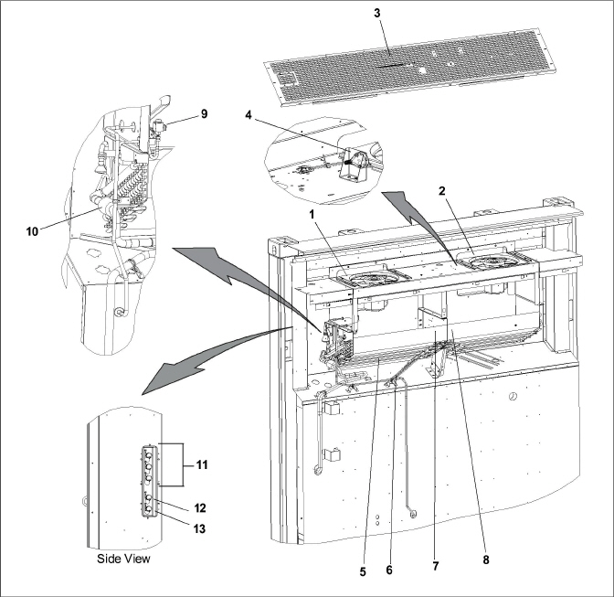
The evaporator section is shown in Figure 3.8. The evaporator fans circulate air through the container by pulling it into the top of the unit, directing it through the evaporator coil to be heated or cooled, and discharging it at the bottom.
Most evaporator components are accessible by removing the upper rear panel or by removing the evaporator fan access panels.
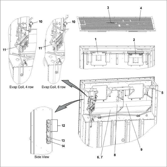
1)Evaporator Fan and Motor (EM1)
2)Evaporator Fan and Motor (EM2)
3)Return Temperature Sensor (RTS) / Return Recorder Sensor (RRS)
4)Humidity Sensor (HS), PIDs < NT2750**
5)Humidity Sensor (HS), PIDs > NT2750**
8)Heat Termination Thermostat (HTT)**
9)Defrost Temperature Sensor (DTS)**
10)Electronic Expansion Valve (EEV)
11)Evaporator Temperature Sensors (ETS1 / ETS2)
12)USDA Probe Receptacles (PR1, PR2, PR3)
13)Cargo Probe Receptacle (PR4)
14)Interrogator Connector Rear (ICR)
- - - - -
** general location, not shown in figure.
Figure 3.9 Evaporator Section - PrimeLINE ONE
1)Evaporator Fan and Motor (EM1)
2)Evaporator Fan and Motor (EM2)
3)Return Temperature Sensor (RTS) / Return Recorder Sensor (RRS) /
7)Heat Termination Thermostat (HTT)**
8)Defrost Temperature Sensor (DTS)**
9)Electronic Expansion Valve (EEV)
10)Evaporator Temperature Sensors (ETS1 / ETS2)
11)USDA Probe Receptacles (PR1, PR2, PR3)
12)Cargo Probe Receptacle (PR4)
13)Interrogator Connector Rear (ICR)
- - - - -
** general location, not shown in figure.
The control box (see Figure 3.10) includes: the manual operation switches, circuit breaker (CB-1), compressor, fan and heater contactors, control power transformer, fuses, keypad, display module, current sensor module, controller module and the communications interface module.
Figure 3.10 Control Box Section
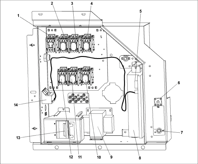
1)Compressor Contactor (CH)
2)Unit Phase A Contactor (PA)
3)Unit Phase B Contactor (PB)
4)Heater Contactor (HR)
5)Controller / DataCORDER Module
6)Remote Monitoring Receptacle (RM)
7)Start-Stop Switch (ST)
8)Controller Battery Pack (standard location)
9)Control Transformer (TS)
10)Evaporator Fan Contactor High Speed (EF)
11)Evaporator Fan Contactor Low Speed (ES)
12)Condenser Fan Contactor (CF)
13)Circuit Breaker 460V (CB1)
14)Current Sensor Module
- - - - -
3.1.8Communications Interface Module
The unit may be equipped with an optional communications interface module, which is a slave module that allows communication between the refrigeration unit and a ship system master central monitoring station. The module will respond to communication and return information over the ship’s main power line. If equipped, this module is located next to the Controller. See the master system technical manual for further information.
3.4Safety and Protective Devices
Unit components are protected from damage by safety and protective devices listed in Table 3–3. These devices monitor the unit operating conditions and open a set of electrical contacts when an unsafe condition occurs.
Open safety switch contacts on either or both of devices IP-CP or HPS will shut down the compressor.
Open safety switch contacts on device IP-CM will shut down the condenser fan motor.
The entire refrigeration unit will shut down if one of the following safety devices open: (a) circuit breaker(s); (b) fuse (F3A/F3B, 7.5A); or (c) evaporator fan motor internal protector(s) - (IP).
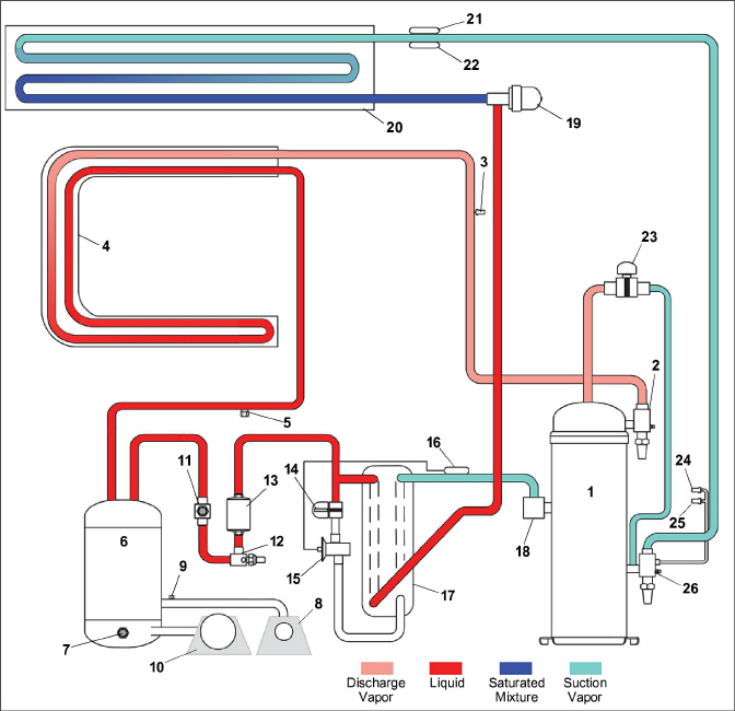
Starting at the compressor, (see Figure 3.11) the suction gas is compressed to a higher pressure and temperature.
The refrigerant gas flows through the discharge line and continues into the air-cooled condenser. When operating with the air-cooled condenser active, air flowing across the coil fins and tubes cools the gas to saturation temperature. By removing latent heat, the gas condenses to a high pressure/high temperature liquid and flows to the receiver, which stores the additional charge necessary for low temperature operation.
When operating with the water-cooled condenser active (see Figure 3.13, Figure 3.14), the refrigerant gas passes through the air-cooled condenser and enters the water-cooled condenser shell. The water flowing inside the tubing cools the gas to saturation temperature in the same manner as the air passing over the air-cooled condenser. The refrigerant condenses on the outside of the tubes and exits as a high temperature liquid. The water-cooled condenser also acts as a receiver, storing refrigerant for low temperature operation.
The liquid refrigerant continues through the liquid line, the filter drier (which keeps refrigerant clean and dry) and the economizer (not active during standard operation) to the electronic expansion valve (EEV).
As the liquid refrigerant passes through the variable orifice of the EEV, the pressure drops to suction pressure. In this process some of the liquid vaporizes to a gas (flash gas), removing heat from the remaining liquid. The liquid exits as a low pressure, low temperature, saturated mix. Heat is then absorbed from the return air by the balance of the liquid, causing it to vaporize in the evaporator coil. The vapor then flows through the suction tube back to the compressor.
On systems fitted with a water pressure switch, the condenser fan will be off when there is sufficient pressure to open the switch. If water pressure drops below the switch cut out setting, the condenser fan will automatically start.
During the standard mode of operation, the normally closed digital unloader valve (DUV) controls the system refrigerant flow and capacity by loading and unloading the compressor in frequent discrete time intervals. If the system capacity has been decreased to the lowest allowable capacity with the DUV, the unit will enter a trim heat mode of operation, during which the controller will pulse the evaporator heaters in sequence with the compressor digital signal in order to absorb the excess capacity.
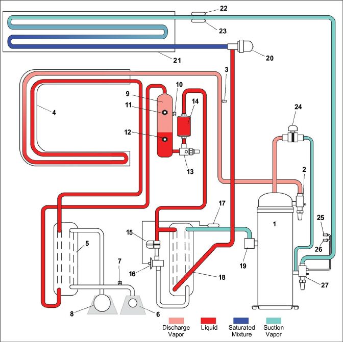
In the economized mode, (see Figure 3.12) the frozen and pull down capacity of the unit is increased by sub-cooling the liquid refrigerant entering the electronic expansion valve. Overall efficiency is increased because the gas leaving the economizer enters the compressor at a higher pressure, therefore requiring less energy to compress it to the required condensing conditions.
Liquid refrigerant for use in the economizer circuit is taken from the main liquid line as it leaves the filter drier. The flow is activated when the controller energizes the economizer solenoid valve (ESV).
The liquid refrigerant flows through the ESV to the expansion valve internal passages, absorbing heat from the liquid refrigerant flowing to the electronic expansion valve. The resultant “medium” temperature/pressure gas enters the compressor at the economizer port fitting.
When the control air temperature falls to 2.0°C (3.6°F) above setpoint, the DUV unloads the compressor’s scroll and begins to reduce the capacity of the unit. Percentage of the unit capacity is accessed through code select 01 (Cd01). For example, if Cd01 displays 70, it indicates that the compressor is operating unloaded with the DUV engaged 30% of the time.
3.5.3Electronic Expansion Valve (EEV)
The microprocessor controls the superheat leaving the evaporator via the electronic expansion valve (EEV), based on inputs from the evaporator pressure transducer (EPT). The microprocessor transmits electronic pulses to the EEV stepper motor, which opens or closes the valve orifice to maintain the superheat setpoint.
Figure 3.11 Refrigeration Circuit Schematic - Standard Operation
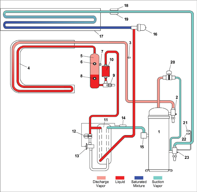
3)Discharge Pressure Transducer (DPT)
8)Receiver Liquid Level / Moisture Indicator
12)Economizer Solenoid Valve (ESV)
13)Economizer Expansion Valve (EXV)
14)Economizer Expansion Valve (EXV) Sensing Bulb
16)Electronic Expansion Valve (EEV)
18)Evaporator Temperature Sensor (ETS1)
19)Evaporator Temperature Sensor (ETS2)
20)Digital Unloader Valve (DUV)
21)Evaporator Pressure Transducer (EPT)
22)Suction Pressure Transducer (SPT)
- - - - -
Figure 3.12 Refrigeration Circuit Schematic - Economized Operation
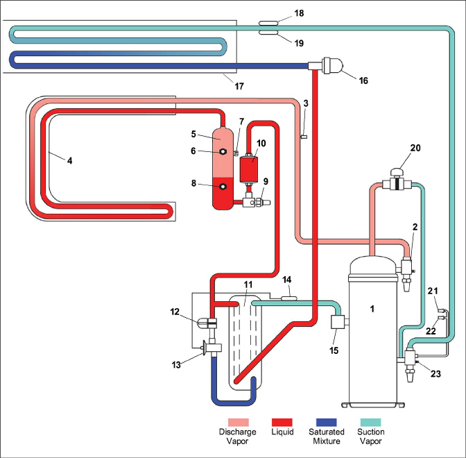
3)Discharge Pressure Transducer (DPT)
8)Receiver Liquid Level / Moisture Indicator
9)Receiver Liquid Line Service Valve
12)Economizer Solenoid Valve (ESV)
13)Economizer Expansion Valve (EXV)
14)Economizer Expansion Valve (EXV) Sensing Bulb
16)Electronic Expansion Valve (EEV)
18)Evaporator Temperature Sensor (ETS1)
19)Evaporator Temperature Sensor (ETS2)
20)Digital Unloader Valve (DUV)
21)Evaporator Pressure Transducer (EPT)
22)Suction Pressure Transducer (SPT)
- - - - -
Figure 3.13 Refrigeration Circuit Schematic - Water-Cooled Condenser (Tube In Shell)
3)Discharge Pressure Transducer (DPT)
14)Economizer Solenoid Valve (ESV)
15)Economizer Expansion Valve (EXV)
16)Economizer Expansion Valve (EXV) Sensing Bulb
19)Electronic Expansion Valve (EEV)
21)Evaporator Temperature Sensor (ETS1)
22)Evaporator Temperature Sensor (ETS2)
23)Digital Unloader Valve (DUV)
24)Evaporator Pressure Transducer (EPT)
25)Suction Pressure Transducer (SPT)
- - - - -
Figure 3.14 Refrigeration Circuit Schematic - Water-Cooled Condenser (Brazed Plate)
3)Discharge Pressure Transducer
12)Receiver Sight Glass / Moisture Indicator
15)Economizer Solenoid Valve (ESV)
16)Economizer Expansion Valve (EXV)
17)Economizer Expansion Valve (EXV) Sensing Bulb
20)Electronic Expansion Valve (EEV)
22)Evaporator Temperature Sensor (ETS1)
23)Evaporator Temperature Sensor (ETS2)
24)Digital Unloader Valve (DUV)
25)Evaporator Pressure Transducer (EPT)
26)Suction Pressure Transducer (SPT)
- - - - -