Section 2
The Carrier Transicold model 69UG15 under-mounted diesel-driven generator set provides a constant electrical power supply for all-electric refrigeration units. This style unit is mounted to the frame rails of the container trailer chassis. The generator set consists of a diesel engine direct-connected to an alternating current generator and mounted in a structural steel frame.
Refer to the following illustrations for generator set component layout:
•UniDrive View (see Figure 2.2, Figure 2.3)
•Front View (see Figure 2.4, Figure 2.5)
•Top View (see Figure 2.6, Figure 2.7)
The engine is a vertical in-line, four cylinder diesel manufactured by Kubota. The generator is a 15 kW, brushless, dual bearing type that supplies nominal 50/60Hz power. Generator sets will start at 50Hz. Once the unit is running, the voltage controller will read the voltage output of the generator and adjust accordingly, to keep the voltage within ISO limits. As the Container becomes loaded, voltage drops and current increases, the generator set will switch windings or speed based on power demand and ambient conditions. The unit will typically run at 50Hz and will vary generator output via winding selection. The speed change to 60 Hz will typically occur when the ambient temperature is high and the unit is heavily loaded.
Electrical controls are mounted in a control box with operating controls and gauges mounted on a control panel, which also serves as the control box cover. The control panel components are protected by a deflector assembly and a windowed control box door.
The 69UG15 is available as a standard configuration, with an Auto Restart option or with Auto Restart and Low Coolant Sensor. The Auto Restart option automatically restarts the unit in the event of a unit shutdown. Auto Restart also offers built-in indicators that signal low oil pressure, high water temperature, overspeed, and other overcrank conditions.
Carrier Transicold’s Ecodriven dual speed option provides an energy saving alternative to the practice of continuously running the generator at full speed. This speed reduction results in increased fuel economy, reduced carbon footprint, and lowers operating costs.
2.2Configuration Identification
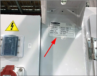
Generator set identification information is provided on a label (See Figure) located below the left mounting pad to the left of the access service door (front facing). The label provides the generator set model number, serial number, and parts identification number (PID). The model number identifies the overall configuration while the PID provides information on specific optional equipment and differences in detailed parts. The model number, serial number and PID number must be included when ordering parts and inquiring about your unit.
Figure 2.1 Label with Generator Set Identification
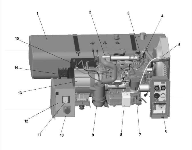
Figure 2.2 Unit View, UniDrive (PIDs prior to UG 2019)
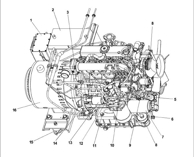
1)Battery Charger
2)Battery
3)Intake Air Heater
4)V-Belt
5)Oil Pressure Sender
6)Oil Pressure Switch
7)Oil Filter
8)Engine Shockmount
9)Engine Speed Sensor
10)Injector Pump
11)Lube Oil Dipstick / Fuel Cap
12)Mechanical Fuel Pump
13)Starter
14)Flywheel Access Cover
15)Generator Shockmount
16)Generator
- - - - -
Figure 2.3 Unit View, UniDrive (PIDs UG2019 and Up)
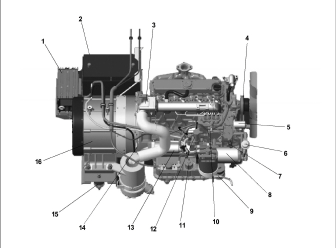
1)Battery Charger
2)Battery
3)Intake Air Heater
4)V-Belt
5)Oil Pressure Sender
6)Oil Pressure Switch
7)Engine Speed Sensor
8)Oil Filter
9)Engine Shockmount
10)Injector Pump
11)Lube Oil Dipstick / Fuel Cap
12)Mechanical Fuel Pump
13)Starter
14)Flywheel Access Cover
15)Generator Shockmount
16)Generator
- - - - -
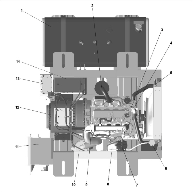
Figure 2.4 Unit View, Front (PIDs prior to UG2019)
1)Fuel Tank
2)Intake Air Heater
3)Water Temperature Switch
4)Water Temperature Sensor
5)Radiator
6)Controls
7)Fuel Filter / Fuel Heater
8)Coolant Overflow Bottle
9)Air Cleaner
10)Receptacle
11)Circuit Breaker
12)Receptacle Box
13)Generator
14)Battery Charger
15)Battery
- - - - -
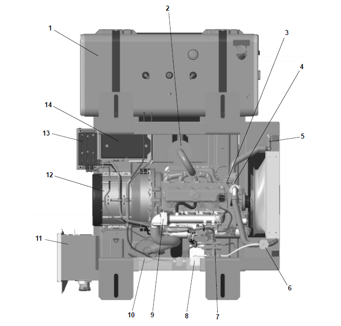
Figure 2.5 Unit View, Front (PIDs UG2019 and Up)
1)Fuel Tank
2)Intake Air Heater
3)Water Temperature Switch
4)Water Temperature Sensor
5)Radiator
6)Controls
7)Fuel Filter / Fuel Heater
8)Coolant Overflow Bottle
9)Air Cleaner
10)Receptacle
11)Circuit Breaker
12)Receptacle Box
13)Generator
14)Battery Charger
15)Battery
- - - - -
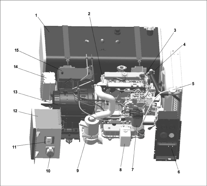
Figure 2.6 Unit View, Top (PIDs prior to UG2019)
1)Fuel Tank
2)Muffler
3)Water Temperature Switch
4)Water Temperature Sensor
5)Low Coolant Sensor
6)Radiator
7)Fuel Filter / Fuel Heater
8)Coolant Overflow Bottle
9)Intake Air Heater
10)Air Cleaner
11)Receptacle Box
12)Generator
13)Battery Charger
14)Battery
- - - - -
Figure 2.7 Unit View, Top (PIDs UG2019 and Up)
1)Fuel Tank
2)Muffler
3)Water Temperature Switch
4)Water Temperature Sensor
5)Low Coolant Sensor
6)Radiator
7)Fuel Filter / Fuel Heater
8)Coolant Overflow Bottle
9)Intake Air Heater
10)Air Cleaner
11)Receptacle Box
12)Generator
13)Battery Charger
14)Battery
- - - - -
The engine is a vertical, in-line four cylinder diesel engine, which is directly connected to the alternating current generator. Information on the major engine systems is provided in the following sub-paragraphs.
Auxiliary engine equipment consists of the battery, solid state battery charging system, “spin-on” lube oil filter, fuel filter and other necessary components for proper unit operation. The water pump and the radiator cooling fan are belt-driven from the engine crankshaft. All references to engine are as viewed from the fly wheel end.
Separately bound manuals covering the diesel engine are available:
•62-10865, V2203-DI Engine Workshop
•62-11695, V2203-DI Engine Parts List
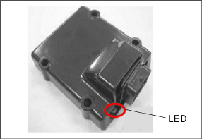
2.3.1Electronic Governor Module
The Electronic Governor (EG) module (Figure 2.8) is a solid state control module pre-programmed for 1800 RPM high speed and 1500 RPM low speed operation.
The EG unit has an LED which may be used to diagnose failures within the electronic speed control system, refer to Section 4.5 for additional troubleshooting information on diagnosing failures.
All threads used on the engine are metric except for the oil drain plug, which is American Standard Pipe Thread (NPT).
Figure 2.8 Electronic Governor Module
The air cleaner is designed to prolong engine life and performance by preventing dirt and grit from entering the engine and causing excessive wear on all operating parts. In order for the air filter to operate properly, the operator must regularly maintain the air cleaner equipment in accordance with the instructions provided within this document.
The fuel system is fitted with an in-line fuel strainer and a fuel filter, which also acts as a water separator. The fuel system is shown in Figure 2.9. The fuel heater system is located in the fuel filter and uses a 12 volt heater to heat fuel as it passes through the fuel filter, see Figure 2.9.
Figure 2.9 Fuel System Diagram
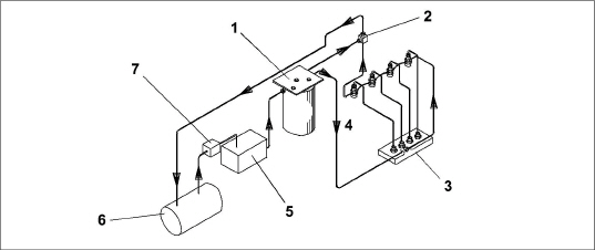
1)Fuel Filter / Heater
2)Injector Nozzles
3)Bleed Valve
4)Injection Pump
5)Mechanical Lift Pump
6)Fuel Tank
7)In-Line Fuel Strainer (option)
- - - - -
2.3.5Lube Oil Filter Arrangement
The engine lubricating oil filter is mounted in a horizontal arrangement and shown in Figure 2.10.
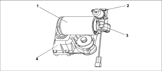
1)Oil Filter (Primary)
2)Oil Pressure Sender
3)Oil Pressure Switch
4)Oil Pan
- - - - -
2.4Alternating Current Generator
The generator is directly bolted to the engine and supplies nominal 50/60Hz power depending on the load requirement.
The solid state battery charger is located in front of the battery. The battery charger is powered by the generator, and this input is protected by fuses located in the receptacle box. The battery charger produces a tapered charge (40 amps maximum) and is designed not to overcharge the battery.
Observe proper polarity when installing the battery or connecting a battery charger. The negative battery terminal must be grounded. Reverse polarity may damage the charging system. When charging the battery in unit, isolate the battery by disconnecting the negative battery terminal first, then the positive. Once the battery has been charged, connect the positive battery terminal first, then the negative.
Voltage Controller maintains ISO voltage via two-speed and dual winding control. It is used to regulate voltage in order to keep the generator output within ISO limits:
•50Hz - 1500 RPM, 360 - 460 VAC
•60Hz - 1800 RPM, 400 - 500 VAC
2.7Operating Controls & Instruments
Components required for monitoring and controlling the Genset unit are located in the control box, on the control panel and on the receptacle box.
The Oil Pressure Gauge (see Figure 2.11, Figure 2.12) observes normal operating engine oil pressure. Normal oil pressure is 35 to 60 psig (3.3 to 5.2 kg/cm2). The Oil Pressure Sender (see Figure 2.10), located at the oil filter housing, senses lube oil pressure and transmits a signal to the Oil Pressure Gauge.
The Water Temperature Gauge (see Figure 2.11, Figure 2.12) observes water operating temperature. Once the unit has achieved normal running temperature, the coolant temperature is between 82 - 96°C (180 - 205°F). The Water Temperature Sensor senses engine water temperature and transmits a signal to the Water Temperature Gauge.
2.7.3Auto Restart Module (Option)
The Auto Start / Restart module (see Figure 2.12) is provided to simplify the start-up process and provide an automatic restart feature that will automatically attempt to restart the unit in the event of shutdown. Four LEDs are used to indicate shutdown from overcrank, overspeed, low oil pressure, and high water temperature. A fifth LED is used to indicate the unit is running. Refer to Table 2–1 for system Auto Start preset values.
The Auto Restart function will perform a series of six attempts to restart the unit and make three attempts within each series. Once the function has completed all 18 attempts, the unit will automatically lock out future crank attempts. Refer to Table 2–2 for detailed information on Auto Restart sequencing.
A Low Coolant Sensor senses the coolant level inside the radiator and will complete a conductive circuit as long as the probes remain immersed in coolant. When coolant level falls below the probes, a signal is sent to the Auto Restart Module, shutting down the engine and all 12-volt circuitry.
The Ammeter (see Figure 2.11, Figure 2.12) indicates the rate of charge or discharge of the battery charging system. The battery charging system is composed of the battery and the battery charger, either solid state or alternator. During start up, the intake heater draws approximately 42 amps.
The Total Time Meter (see Figure 2.11, Figure 2.12) calculates the total hours the unit has been running, which provides an accurate readout of accumulated engine running time. This data can be used to establish proper maintenance schedules (refer to Table 5–1).
2.7.6Intake Heater Switch (HS)
The Intake Heater Switch (HS) (see Figure 2.11) is a momentary switch. When held in the PREHEAT position, the switch allows approximately 42 amps of battery current to flow into the intake heater, which preheats the air within the intake manifold and allows the engine to start. After starting the engine, the intake heater switch should continue to be held in the ON position for approximately 5 seconds until the engine has developed enough oil pressure to close the oil pressure safety switch.
The Ignition Switch (IGN) (see Figure 2.11) is a momentary switch that has OFF/ON/START positions. When held in the START (ignition) position, it energizes the starter motor solenoid, which in turn allows the starter motor to crank the engine. The switch is released to the RUN position once the engine has started.
2.7.8Ignition Switch (IGN) with Auto Restart option
The Ignition Switch (IGN) (see Figure 2.12) is a maintained contact switch that has the RUN/OFF positions. When switched to the RUN position, it energizes the control module, which in turn controls all functions of the Genset.
2.7.9Intake Heater Timer (IHT)
The Intake Heater Timer (if equipped) (see Figure 2.11) continues to supply power to the intake heater for 3 minutes after initial start-up.
2.7.10Starter Solenoid Timer (SST)
The Starter Solenoid Timer (SST) (see Figure 2.11) limits the amount of time that the starter can be engaged to 15 seconds. If the starter is manually engaged for more than 15 seconds, power will be cut to the starter. Once power has been removed, the starter can again be engaged for up to 15 seconds.
Figure 2.11 Control Panel and Control Box, Standard
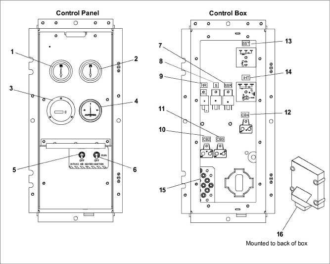
1)Water Temperature Gauge
2)Oil Pressure Gauge
3)Total Time Meter (TT)
4)Ammeter (A)
5)Intake Heater Switch (HS)
6)Ignition Switch (IGN)
7)Starter Solenoid Relay (SSR)
8)Safety Relay (S)
9)Intake Heater Relay (HR)
10)Circuit Breaker (CB2)
11)Circuit Breaker (CB3)
12)Circuit Breaker (CB4)
13)Starter Solenoid Timer (SST)
14)Intake Heater Timer (IHT)
15)Ground Studs
16)Electronic Governor Module (EG)
- - - - -
Figure 2.12 Control Panel and Control Box, Auto Restart
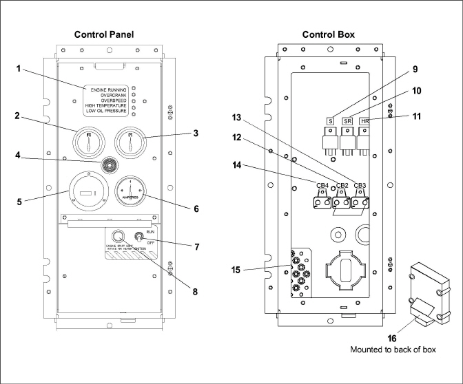
1)Auto Restart Module
2)Water Temperature Gauge
3)Oil Pressure Gauge
4)Engine Start Alarm (Buzzer)
5)Total Time Meter (TT)
6)Ammeter (A)
7)Ignition Switch (IGN)
8)Engine Start / Intake Heater Light
9)Safety Relay (S)
10)Starter Relay (SR)
11)Intake Heater Relay (HR)
12)Circuit Breaker (CB2)
13)Circuit Breaker (CB3)
14)Circuit Breaker (CB4)
15)Ground Studs
16)Electronic Governor Module (EG)
- - - - -
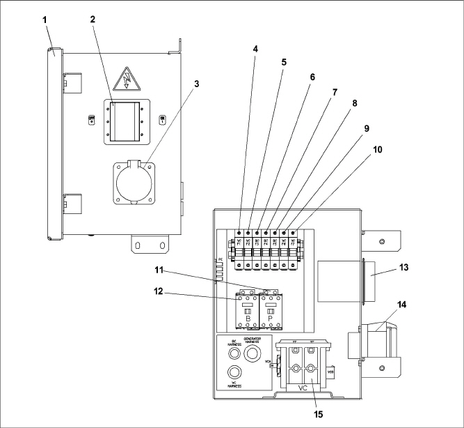
1)Access Cover
2)Circuit Breaker (CB1) Genset
3)Receptacle
4)VCF1, Fuse 1
5)VCF2, Fuse 2
6)BCF3, Fuse 3
7)BCF4, Fuse 4
8)BCF5, Fuse 5
9)VCF6, Fuse 6
10)VCF7, Fuse 7
11)Primary Contactor
12)Boost Contactor
13)Circuit Breaker (CB1) Genset
14)Receptacle
15)Voltage Contactor
- - - - -
Safety devices, such as circuit breakers, fuses, and safety switches protect system components from damage.
The AC generator, solid state battery charger, fuel heater, high water temperature, safety relay, total time meter and intake heater are protected by circuit breakers. If a safety device opens and there is an interruption of electrical current, the electronic governor module will be de-energized, which will also de-energize the fuel solenoid, interrupt the fuel flow to the engine and stop the engine.
In units with auto restart, the engine, engine control devices, and engine monitoring devices are protected by the auto restart module, low coolant sensor (if equipped), circuit breaker, low oil pressure switch, and high water temperature switch. These safety devices monitor system operating conditions and open a set of electrical contacts when an unsafe condition occurs. If a safety device opens and there is an interruption of electrical current, the electronic governor module will be de-energized, which will also de-energize the fuel solenoid, interrupt the fuel flow to the engine and stop the engine.
De-energizing the fuel solenoid shuts off the fuel supply to the engine; thus stopping the engine. Safety device specifications are provided in Table 2–3.
Fuel Tanks |
||
|
Nominal Tank Sizes |
50 Gallon Steel |
Fill Capacity |
52 Gallons (197 liters) |
|
Draw Capacity |
50 Gallons (189 liters) |
|
|
Nominal Tank Sizes |
50 Gallon Aluminum |
Fill Capacity |
52 Gallons (197 liters) |
|
Draw Capacity |
50 Gallons (189 liters) |
|
|
Nominal Tank Sizes |
65 Gallon Steel |
|
Fill Capacity |
67.5 Gallons (256 liters) |
|
Draw Capacity |
65 Gallons (246 liters) |
|
Nominal Tank Sizes |
80 Gallon Aluminum |
Fill Capacity |
85 Gallons (322 liters) |
|
Draw Capacity |
80 Gallons (303 liters) |
|
Weights |
||
|
Battery |
63 lb (28.6 kg) |
Generator (A-C) |
197 lb (89 kg) |
|
Engine (Dry) - without Accessories |
439 lb (199 kg) approximate |
|
Unit (with 50 gallon steel tank, dry) |
- |
|
Unit (with 50 gallon aluminum tank, dry) |
- |
|
Unit (with 65 gallon steel tank, dry) |
1555lb (705 kg) |
|
Unit (with 80 gallon aluminum tank, dry) |
|
|
Bore /Stroke: |
3.26 in. (83 mm) / 4.03 in. (102.4 mm) |
|
Compression Ratio: |
22.0 to 1 |
|
Cylinders (Number): |
Four |
|
Displacement: |
135.2 cubic inches (2.22 liters) (2216 cm3) |
|
Firing Order: |
1-3-4-2 |
|
Lubrication System: |
Oil Pressure Safety Switch Setting Opens |
18 psig (1.27 kg/cm2) |
Capacity |
Engine - 15.0 US quarts (14.2 liters), includes standard filter. |
|
Oil Level Indicator |
Dipstick in oil pan or fill cap
NOTE: To check oil level on engines with the dipstick mounted in the fill cap, remove the cap and wipe the dipstick clean. Insert the cap back onto the oil fill tube, then remove to check level. It is not necessary to screw the cap back into the fill tube when checking level. DO NOT add oil if level is within the “safe” range. If needed, add oil to bring level within the “safe” range. Screw cap fully into fill tube after checking level. |
|
Lube Oil Specification |
Use a heavy duty lubricating oil conforming to American Petroleum Institute (API) Service Classification CF or better. |
|
Lube Oil Viscosity |
Outdoor Temperature |
|
Fahrenheit: 0°F to 45°F Centigrade: -18°C to 7°C SAE: 10W30 or Mobile Delvac 1* |
||
Fahrenheit: 45°F and above Centigrade: 7°C and above SAE: 10W30 or 15W40 or Mobile Delvac 1* |
||
* Mobile Delvac 1, 5W-40 or 15W-40 is the only approved synthetic oil. |
||
Fuel and Fuel Heater Thermostat (FHT): |
||
Fuel |
Winter |
Diesel No. 2 with winter blends |
Summer |
Diesel No. 2 |
|
FHT |
Winter |
Close on temperature fall @ 45+/- 6.5°F |
Summer |
Open on temperature rise @ 75+/- 6.5°F |
|
Power Consumption: 150 Watts @ +/- 10% at 14 VDC |
||
Diesel Fuel Specification Type and Sulfur Content % (ppm) used, must be compliant with all applicable emission regulations for the area in which the engine is operated. Since KUBOTA diesel engines of less than 56 kW (75 hp) utilize EPA Tier 4 and Interim Tier 4 standards, the use of ultra low sulfur fuel is mandatory for these engines, when operated in US EPA regulated areas. Therefore, please use No.2-D S15 diesel fuel. Ultra Low Sulfur Diesel (ULSD) 15 ppm or 0.0015 wt.% |
||
Intake Heater: |
Amperage - 42 amps at 12 VDC |
|
Resistance (cold) - Approx. 0.3 ohms |
||
Horsepower: |
24.8 HP @ 1800 RPM at sea level. (SAE J1995 Gross Power Rating) |
|
Cooling System: |
Capacity |
6 U.S. quarts (5.68 liters) - includes 1 quart (0.95 liter) in coolant recovery bottle. (Refer to section 4.4.5) |
Anti-Freeze: Extended Life |
The cooling system is factory charged with a 50/50 mix of extended life coolant (ELC) and deionized water. This mixture provides protection to -34°F (-37°C). For replacement, use Shell Rotella ELC Nitrite Free Pre-Diluted 50/50 antifreeze / coolant. |
|
Water Temperature Safety Switch Setting: |
||
Opens |
230 +/- 5°F (110 +/- 3°C) |
|
Resets |
200°F (93°C) - minimum |
|
Thermostat: |
||
Starts to open |
177 to 182°F (80 to 84°C) |
|
Fully open |
203°F (95°C) |
|
Low Coolant Sensor: |
||
Opens |
Los of 32 ounces of coolant or more |
|
Closes |
Refilling of radiator to proper level |
|
Lubrication System: |
Oil Pressure |
35 to 60 psig (3.3 to 5.2 kg/cm) |
Electrical: |
Generator |
400-500 VAC @ 60 hz 360-460 VAC @ 50 hz |