Section 4
4.1Temperature Control Microprocessor System
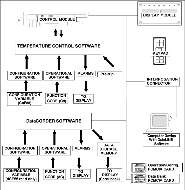
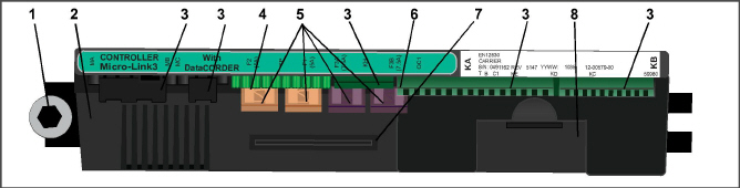
The temperature control Micro-Link 3 microprocessor system (see Figure 4.1) consists of a keypad, display module, control module (controller), and interconnecting wiring. The controller houses the temperature control software and the DataCORDER Software. The temperature control software functions to operate the unit components as required to provide the desired cargo temperature and humidity.
The DataCORDER software functions to record unit operating parameters and cargo temperature parameters for future retrieval. Coverage of the temperature control software begins with Section 4.2. Coverage of the DataCORDER software is provided in Section 4.8.
The keypad and display module serve to provide user access and readouts for both of the controller functions, temperature control, and DataCORDER. The functions are accessed by keypad selections and viewed on the display module. The components are designed to permit ease of installation and removal.
Figure 4.1 Temperature Control System
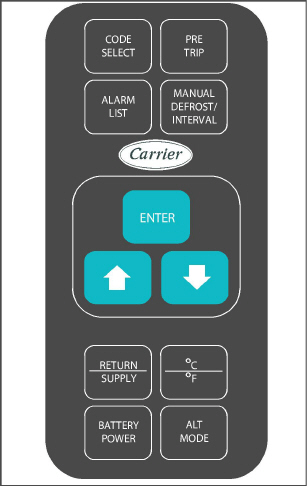
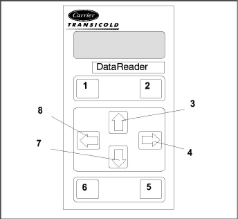
The keypad (Figure 4.2) is mounted on the right-hand side of the control box. The keypad consists of 11 push button switches that act as the user’s interface with the controller. Descriptions of the switch functions are provided in Table 4–1.
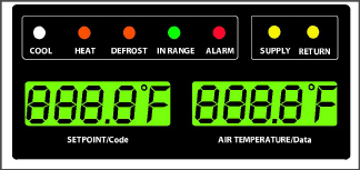
The display module (Figure 4.3) consists of five digital displays and seven indicator lights. Indicator lights include:
1.COOL − White or Blue LED: Energized when the refrigerant compressor is energized.
2.HEAT − Orange LED: Energized to indicate heater operation in heat mode, defrost mode, or dehumidification.
3.DEFROST − Orange LED: Energized when the unit is in the defrost mode.
4.IN RANGE − Green LED: Energized when the controlled temperature probe is within specified tolerance of set point.
The controlling probe in perishable range is the SUPPLY air probe and the controlling probe in frozen range is the RETURN air probe.
5.SUPPLY − Yellow LED: Energized when the supply air probe is used for control. When this LED is illuminated, the temperature displayed in the AIR TEMPERATURE display is the reading at the supply air probe. This LED will flash if dehumidification or humidification is enabled.
6.RETURN − Yellow LED: Energized when the return air probe is used for control. When this LED is illuminated, the temperature displayed in the AIR TEMPERATURE display is the reading at the return air probe. This LED will flash if dehumidification or humidification is enabled.
7.ALARM − Red LED: Energized when an active or an inactive shutdown alarm is in the alarm queue.
Do not remove wire harnesses from controller unless you are grounded to the unit frame with a static safe wrist strap.
Unplug all controller wire harness connectors before performing arc welding on any part of the container.
Do not attempt to use an ML2i PC card in an ML3 equipped unit. The PC cards are physically different and will result in damage to the controller.
Do not attempt to service the controller. Breaking the seal will void the warranty.
The Micro-Link 3 controller is a single module microprocessor as shown in Figure 4.4. It is fitted with test points, harness connectors and a software card programming port.
The controller software is a custom designed program that is subdivided into the configuration software and the operational software. The controller software performs the following functions:
a.Control supply or return air temperature to required limits, provide modulated refrigeration control, electric heat control, and defrost. Defrost is performed to clear buildup of frost and ice from the coil to ensure continuous conditioned air delivery to the load.
b.Provide default independent readouts of set point and supply or return air temperatures.
c.Provide ability to read, and if applicable, modify the configuration software variables, operating software function codes, and alarm code indications.
d.Provide a Pre-trip step-by-step checkout of refrigeration unit performance, including proper component operation, electronic and refrigeration control operation, heater operation, probe calibration, pressure limiting, and current limiting settings.
e.Provide battery-powered ability to access or change selected codes and set points without AC power connected.
f.Provide the ability to reprogram the software through the use of a memory card.
4.2.1Configuration Software (CnF Variables)
The configuration software is a variable listing of the components available for use by the operational software. This software is factory-installed in accordance with the equipment fitted and options listed on the original purchase order. Changes to the configuration software are required only when a new controller has been installed or a physical change has been made to the unit such as the addition or removal of an option. A configuration variable list is provided in Table 4–4. Change to the factory-installed configuration software is achieved via a configuration card or by communications.
6.Control Circuit Power Connection (located on back of controller)
- - - - -
4.2.2Operational Software (Cd Function Codes)
The operational software is the actual operation programming of the controller which activates or deactivates components in accordance with current unit operation conditions and selected modes of operation.
The programming is divided into function codes. Some of the codes are read only, while the remaining codes may be user configured. The value of the user configurable codes can be assigned in accordance with user desired mode of operation. A list of the function codes is provided in Table 4–5.
To access the function codes:
a.Press CODE SELECT, then press an arrow key until the left window displays the desired function code.
b.The right window will display the selected function code value for five seconds before returning to the default display mode.
c.If additional time is required, pressing the ENTER key will extend the display time to 30 seconds.
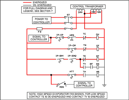
General operation sequences for cooling, heating, and defrost are provided in the following sub-paragraphs. Schematic representation of controller actions are provided in Figure 4.5 and Figure 4.8.
The operational software responds to various inputs. These inputs come from the temperature and pressure sensors, the temperature set point, the settings of the configuration variables and the function code assignments. The action taken by the operational software will change if any of the inputs changes. Overall interaction of the inputs is described as a “mode” of operation. The modes of operation include perishable (chill) mode and frozen mode. Descriptions of the controller interaction and modes of operation are provided in the following sub-paragraphs.
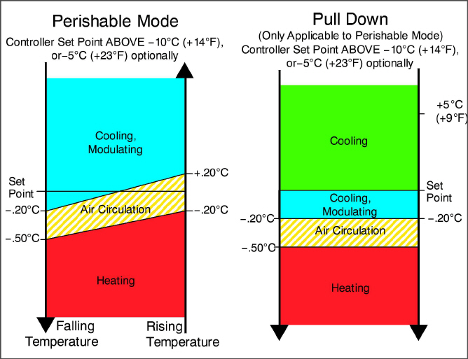
4.3.1Perishable Mode Temperature Control
The unit is capable of maintaining supply air temperature to within +/- 0.25°C (+/- 0.5°F) of set point. Supply air temperature is controlled by positioning of the suction modulation valve (SMV), cycling of the compressor, and cycling of the heaters.
In Perishable Mode, the controller maintains the supply air temperature at set point, the SUPPLY indicator light is illuminated and the default reading on the display window is the supply temperature sensor reading.
When the supply air temperature enters the in-range temperature tolerance (Cd30), the green IN-RANGE light will energize.
When CnF26 (Heat Lockout Temperature) is set to -10°C, perishable mode is active with set points above -10°C (+14°F). When CnF26 is set to -5°C, perishable mode is active with set points above -5°C (+23°F).
When the system is in Perishable Pulldown Mode, the highest priority is given to bringing the container down to set point. When cooling from a temperature that is more than 5°C (9°F) above set point, the system will be in Perishable Pulldown Mode, and the SMV will open to reduce the pulldown time.
However, pressure and current limit functions may restrict the valve if either exceeds the preset value.
Perishable Steady State is used to maintain the control temperature near a setpoint that is above the heat lockout temperature.
The operational software is designed so the SMV will begin to close as the set point is reached. The SMV will continue to close and restrict refrigerant flow until the capacity of the unit and the load are balanced.
If the temperature drops below the set point, the compressor will remain running for a few minutes. This is to accommodate any initial undershoot which might occur. After this time has expired and the temperature is 0.2°C (0.4°F) or greater below the set point, the compressor will be turned OFF.
If the temperature drops to 0.5°C (0.9°F) below set point, the heaters will be energized. The heaters will de-energize when the temperature rises to 0.2°C (0.4°F) below the set point. The compressor will not restart until the temperature rises to 0.2°C (0.4°F) above the set point and three minutes have elapsed since the last compressor turn off.
4.3.4Perishable Idle, Air Circulation
Perishable Idle Mode is used when it is unnecessary to run the compressor to maintain control temperature. If the controller has determined that cooling is not required or the controller logic determines suction pressure is at the low pressure limit, the unit will transition to Perishable Idle Mode. During Perishable Idle Mode, the compressor is turned off, but the evaporator fans continue to run to circulate air throughout the container. If temperature rises +0.2°C above set point, the unit will transition back to perishable steady state.
When it is necessary to raise the control temperature, the system will enter Perishable Heating Mode. If the temperature drops to 0.5°C (0.9°F) below set point, the unit will transition to Perishable Heating Mode, and the heaters will be energized. The unit will transition back to Perishable Idle Mode when the temperature rises to 0.2°C (0.4°F) below the set point, and the heaters will de-energize.
Figure 4.5 Controller Operation − Perishable Mode
4.3.6Perishable Mode Dehumidification
Dehumidification is provided to reduce the humidity levels inside the container. Dehumidification is activated when a humidity value is set at Cd33. The yellow SUPPLY LED will flash ON and OFF every second to indicate that dehumidification is active. Once dehumidification is active and the following conditions are satisfied, the controller will activate the heat relay to begin dehumidification.
1.The humidity sensor reading is above the humidity set point (Cd33).
2.The unit is in the perishable steady state mode, and the supply air temperature is less than 0.25°C (0.45°F) above set point.
3.The heater debounce timer (three minutes) has timed out.
4.Heater termination thermostat (HTT) is closed.
If the above conditions remain true for at least one hour, the evaporator fans will switch from high speed to low speed. Evaporator fan speed will then switch every hour, as long as the 4 conditions are met (see Bulb Mode, Section 4.3.7 for different evaporator fan speed options).
If any condition except for item (1) becomes false OR if the relative humidity sensed is 2% below the dehumidification set point, the high speed evaporator fans will be energized.
During dehumidification, power is applied to the defrost heaters. This added heat load causes the controller to open the SMV to match the increased heat load while still holding the supply air temperature very close to the set point.
Opening the SMV reduces the temperature of the evaporator coil surface, which increases the rate at which water is condensed from the passing air. Removing water from the air reduces the relative humidity. When the relative humidity sensed is 2% below set point, the controller de-energizes the heat relay. The controller will continue to cycle heating to maintain relative humidity below the selected set point. If the dehumidification mode is terminated by a condition other than the humidity sensor, e.g., an out-of-range or compressor shutdown condition, the heat relay is de-energized immediately.
Two timers are activated during dehumidification to prevent rapid cycling and consequent contactor wear:
1.Heater debounce timer (three minutes) − The heater debounce timer is started whenever the heater contactor status is changed. The heat contactor remains energized (or de-energized) for at least three minutes even if the set point criteria is satisfied.
2.Out-of-range timer (five minutes) − The out-of-range timer is started to maintain heater operation during a temporary out-of-range condition. If supply air temperature remains outside of the user selected in-range setting for more than five minutes, the heaters will be de-energized to allow the system to recover. The out-of-range timer starts as soon as the temperature exceeds the in-range tolerance value set by Cd30.
4.3.7Perishable, Dehumidification − Bulb Mode
Bulb mode is an extension of dehumidification which allows changes to the evaporator fan speed and/or defrost termination set points.
Bulb mode is active when Cd35 is set to “Bulb.” Once bulb mode is activated, the user may then change the dehumidification mode evaporator fan operation from the default (speed alternates from low to high each hour) to constant low or constant high speed. This is done by toggling Cd36 from its default of “alt” to “Lo” or “Hi” as desired. If low speed evaporator fan operation is selected, the user has the additional capability of selecting dehumidification set points from 60 to 95% (instead of the normal 65 to 95%).
In addition, if bulb mode is active, Cd37 may be set to override the previous defrost termination thermostat (DTT) settings (refer to Section 4.3.17). The temperature at which the DTT will be considered “open” may be changed [in 0.1°C (0.2°F) increments] to any value between 25.6°C (78°F) and 4°C (39.2°F). The temperature at which the DTT is considered closed for interval timer start or demand defrost is 10°C (50°F) for “open” values from 25.6°C (78°F) down to a 10°C (50°F) setting. For “open” values lower than 10°C, the “closed” values will decrease to the same value as the “open” setting. Bulb mode is terminated when:
1.Bulb mode code Cd35 is set to “Nor.”
2.Dehumidification code Cd33 is set to “Off.”
3.The user changes the set point to one that is in the frozen range.
When bulb mode is disabled by any of the above, the evaporator fan operation for dehumidification reverts to “alt” and the DTS termination setting resets to the value determined by CnF41.
Economy fan mode is an extension of Perishable Mode, and is only applicable to units with two speed evaporator fan motors. Economy Mode is activated Cd34 is set to “ON.” Economy Mode is provided for power saving purposes, and is generally used during the transportation of temperature tolerant cargo or non-respiration items that do not require high airflow for removing respiration heat. There is no active display that indicates Economy Mode has been activated. To check for economy fan mode, perform a manual display of Cd34.
In order to achieve economy mode, a perishable set point must be selected prior to activation. When economy mode is active, the evaporator fans will be controlled as follows:
•At the start of each cooling or heating cycle, the evaporator fans will run in high speed for three minutes.
•After the initial three minutes, they will then be switched to low speed any time supply air temperature is within +/-0.25°C (0.45°F) of set point and return air temperature is less than or equal to supply air temperature +3°C (5.4°F).
•The fans will continue to run in low speed for one hour. At the end of the hour, the evaporator fans will switch back to high speed and the cycle will be repeated.
4.3.9Perishable Mode Cooling − Sequence of Operation
In Standard Perishable Mode, the evaporator motors run in high speed. In Economy Fan Mode, fan speed is varied.
In low temperature ambients, the condenser fan will be cycled by the controller to maintain proper condensing pressure.
a.With supply air temperature above set point and decreasing, the unit will cooling with the condenser fan motor (CF), compressor motor (CH), evaporator fan motors (EF) energized, and the white COOL light illuminated (see Figure 4.6).
Figure 4.6 Perishable Mode Cooling
b.When supply air temperature decreases to a predetermined tolerance above set point (Cd30), the green IN RANGE light is illuminated.
c.As the air temperature continues to fall, modulating cooling starts as the supply air temperature approaches set point.
d.The controller continuously monitors supply air temperature. Once the supply air temperature falls below set point and 0% SMV position is reached, the controller periodically records the supply air temperature, set point, and time. A calculation is then performed to determine temperature drift from set point over time. If the calculation determines that cooling is no longer required, contacts TC and TN are opened to de-energize the compressor motor and the condenser fan motor.
e.The evaporator fan motors continue to run to circulate air throughout the container. The green IN−RANGE light remains illuminated as long as the supply air is within tolerance of set point.
f.When the supply air temperature increases to 0.2°C (0.4°F) above set point and the three minute off time has elapsed, relays TC and TN are energized to restart the compressor and condenser fan motor. The white COOL light is also illuminated.
4.3.10Perishable Mode Heating - Sequence of Operation
The unit will heat only when in the Perishable Mode, relay TH is electronically locked out when in the Frozen Mode.
a.If the supply air temperature decreases 0.5°C (0.9°F) below set point, the system enters the heating mode (see Figure 4.5). The controller closes contacts TH (see Figure 4.7) to allow power flow through the heat termination thermostat (HTT) to energize the heaters (HR). The orange HEAT light is also illuminated. The evaporator fans continue to run to circulate air throughout the container.
b.When the supply temperature rises to 0.2°C (0.4°F) below set point, contact TH opens to de-energize the heaters. The HEAT light is also de-energized. The evaporator fans continue to run to circulate air throughout the container.
c.The safety heater termination thermostat (HTT) is attached to an evaporator coil circuit and will open the heating circuit if overheating occurs.
Figure 4.7 Perishable Mode Heating
4.3.11Frozen Mode - Temperature Control
In Frozen Mode, the controller maintains the return air temperature at set point, the yellow RETURN indicator light is illuminated, and the default reading on the display window is the return temperature sensor (RTS) reading.
When the return air temperature enters the in-range temperature tolerance (Cd30), the green IN-RANGE light will energize.
With CnF26 (Heat Lockout Temperature) is set to -10°C, frozen mode is active with set points at or below -10°C (+14°F). With CnF26 set to -5°C, frozen mode is active at or below -5°C (+23°F).
When the system is in Frozen Mode, the highest priority is given to bringing the container down to set point.
When return air temperature is greater than 0.2°C (0.4°F) above the frozen set point and the three minute time delay has been met, the unit will always operate at full capacity with the suction modulation valve open as allowed by current and pressure limiting.
Frozen range cargoes are not sensitive to minor temperature changes. The method of temperature control employed in frozen range takes advantage of this fact to greatly improve the energy efficiency of the unit. Temperature control in frozen range is accomplished by cycling the compressor on and off as the load demand requires.
The unit will operate in the conventional frozen mode when the controller set point is at or below the frozen range and Economy Mode (Cd34) is set to “OFF.”
Figure 4.8 Controller Operation − Frozen Mode
When temperature drops to set point minus 0.2°C (0.4°F) and the compressor has run for at least five minutes, the unit will transition to the frozen idle mode. The compressor is turned off and the evaporator fans continue to run to circulate air throughout the container. If temperature rises above set point +0.2°C, (0.4°F) the unit will transition back to the frozen steady state mode.
On start up of the unit, SMV will reset to a known open position. This is accomplished by assuming the valve was fully open, driving it fully closed, resetting the percentage open to zero, then opening to a known 21% staging position.
To prevent rapid cycling of the compressor, a three minute compressor off time must be satisfied before the compressor will restart. Under a condition of rapidly changing return air temperature, the time delay may allow the return air temperature to rise slightly above set point temperature before the compressor can restart.
If the temperature drops 10°C (18°F) below set point, the unit will transition to the frozen “heating” mode. The evaporator fans are brought to high speed, and the heat from the fans is circulated through the container. The unit will transition back to frozen steady state when the temperature rises back to the transition point.
In order to activate economy frozen mode operation, a frozen set point temperature must be selected, and Cd34 (Economy Mode) set to “ON.” When economy mode is active, the system will perform normal frozen mode operations except that the entire refrigeration system, excluding the controller, will be turned off when the control temperature is less than or equal to the set point -2°C.
After an off-cycle period of 60 minutes, the unit will turn on high speed evaporator fans for three minutes and then check the control temperature. If the control temperature is greater than or equal to the frozen set point +0.2°C, the unit will restart the refrigeration system and continue to cool until the previously mentioned off-cycle temperature criteria are met. If the control temperature is less than the frozen set point +0.2°C, the unit will turn off the evaporator fans and restart another 60 minute off-cycle.
4.3.16Frozen Mode Cooling - Sequence of Operation
NOTES
1.In the Frozen Mode the evaporator motors run in low speed.
2.In low temperature ambients, the condenser fan will be cycled by the controller to maintain proper condensing pressure.
a.When the return air temperature is above set point and decreasing, the unit will be cooling with the condenser fan motor (CF), compressor motor (CH), evaporator fan motors (ES) energized and the white COOL light illuminated (see Figure 4.9).
b.When the return air temperature decreases to a predetermined tolerance above set point, the green IN-RANGE light is illuminated.
c.When the return air temperature decreases to 0.2°C (0.4°F) below set point, contacts TC and TN are opened to de-energize the compressor and condenser fan motors. The white COOL light is also de-energized.
d.The evaporator fan motors continue to run in low speed to circulate air throughout the container.
e.The green IN-RANGE light remains illuminated as long as the return air is within tolerance of set point.
f.When the return air temperature increases to 0.2°C (0.4°F) above set point and the three minute off time has elapsed, relays TC and TN are energized to restart the compressor and condenser fan motors. The white COOL light is also illuminated.
Defrost is initiated to remove ice buildup from the evaporator coil which can obstruct air flow and reduce the cooling capacity of the unit. The defrost cycle may consist of up to three distinct operations. The first is de-icing of the coil, the second is a probe check cycle and the third is snap freeze.
De-icing of the coil consists of removing power to the cooling components (compressor, evaporator fans, condenser fan), and turning on the heaters, which are located below the evaporator coil. During normal operation, de-icing will continue until temperatures indicate that the ice on the coil has been removed, proper air flow has been restored, and the unit is ready to control temperature efficiently.
After de-icing, and depending on unit configuration, a Defrost/Probe Check and/or Snap Freeze may occur:
•During Defrost / Probe Check, the evaporator fans are allowed to run for a period of time after de-icing in order to validate the accuracy of the temperature sensors, and confirm that defrost was executed properly. Refer to Probe Diagnostics, Section 5.10 for additional information.
•Defrost / Snap Freeze allows the system to cool for a period of time after de-icing, with the evaporator fans turned off. This allows for the removal of latent de-icing heat from the evaporator coils, and freezes any remaining moisture that might otherwise be blown into the container.
In perishable mode, perishable-pull down mode, or frozen mode, automatic defrost starts with an initial defrost set to three hours and then adjusts the interval to the next defrost based on the accumulation of ice on the evaporator coil. In this way, defrosts are scheduled to occur only when necessary.
In frozen mode, once the frozen set point has been reached, automatic defrost will set the time interval to 12 hours for the first two defrosts, and then adjust to 24 hours thereafter.
All defrost interval times reflect the number of compressor run time hours since the last defrost cycle. The minimum defrost interval in the automatic setting is three hours while the maximum is 24, refer to Defrost Intervals for more information, Section 4.3.20.
In frozen mode the amount of actual time necessary to accumulate defrost interval time will exceed the defrost interval time by a factor of two to three depending on the compressor duty-cycle. Defrost interval time is only accumulated when the compressor is running, and the Defrost Termination Sensor (DTS) reads less than 10°C (50°F), at which point the Defrost Termination Thermostat (DTT) is considered closed.
If defrost does not terminate correctly and temperature reaches the set point of the Heat Termination Thermostat (HTT), the HTT will open to de-energize the heaters (AL59 & AL60). If the HTT does not open and termination does not occur within two hours, the controller will terminate defrost. AL60 will be activated to inform of a possible DTS failure.
Initiation of defrost is dependent on the state of the Defrost Temperature Thermostat (DTT). The functionality of the DTT is controlled by the system software, based on the temperature reading of the Defrost Termination Sensor (DTS). In the case of a failed DTS, the RTS may be used to determine the state of the DTT.
Defrost cannot be initiated when the DTT is considered OPEN, because an open DTT indicates that the temperature is too high for ice to build up. Defrost can only occur when the temperature sensed by the DTS is low enough to CLOSE the DTT.
If the DTT is closed, the unit is in Perishable or Frozen Mode, and the Controlled Atmosphere Vent is closed (if applicable), then defrost can be initiated when any one of the following additional conditions become true:
1.Manual
defrost is initiated by the operator. The Manual Defrost Switch (MDS),
located on the front of the unit, is a momentary toggle switch that must
be held closed until defrost is initiated. The MDS is ignored during Pretrip,
and the DTT must be considered CLOSED for MDS activation to work.
Manual defrost can also be initiated by pressing the MANUAL DEFROST/INTERVAL
key for greater than 5 seconds, or pressing the PRE TRIP key and the
ALT MODE key for greater than 5 seconds. If the two key method is used
the display may show “P” or “Dc” while waiting for defrost to initiate.
2.The Defrost Interval Timer reaches or exceeds the Defrost Interval.
3.During Pretrip, defrost may occur during tests P-8, and P-10. Defrost is forced during Pretrip test P-9.
4.Temperature Probe Diagnostics logic determines that a Probe Check is necessary based on temperature values currently reported by the supply and return probes.
5.An Initiate Defrost command is sent via communications.
6.The controller Demand Defrost configuration variable (CnF40) is set to “In” and the unit has been in pull down operation for over 2.5 hours without reaching set point.
7.The microprocessor can determine if defrost is required by calculating the difference between return air temperature and supply air temperature (Delta T). If the temperature difference between return air and supply air is too great, it indicates reduced airflow over the evaporator coil, and a defrost cycle may be required:
a.In Perishable Pull Down - Defrost will be initiated if Delta T increases to greater than 12°C, DTT is closed, and 90 minutes of compressor run time have been recorded.
b.In Frozen Mode - Defrost will be initiated if Delta T increases to greater than 16°C, DTT is closed, and 90 minutes of compressor run time have been recorded.
c.In Perishable Steady State - A baseline Delta T is used to determine when defrost should be activated. The baseline is recorded after completion of an initial defrost cycle. In order to record a baseline Delta T, the unit must be cooling, and the evaporator fans and heaters must remain in a stable state for a period of five minutes. Defrost will then be initiated if Delta T increases to greater than 4°C above the baseline, the DTT is closed, and 90 minutes of compressor run time have been recorded.
During defrost, the Defrost Relay is energized, the orange DEFROST light is illuminated, and the orange HEAT light is illuminated.
Defrost may be initiated any time the defrost temperature sensor reading falls below the controller DTT set point. Defrost will terminate when the defrost temperature sensor reading rises above the DTT set point. The DTT is not a physical component. It is a controller setting that acts as a thermostat, “closing” (allowing defrost) when the defrost temperature sensor reading is below the set point and “opening” (terminating or preventing defrost) when the sensor temperature reading is above set point. When the unit is operating in bulb mode (refer to Section 4.3.7), special settings may be applicable.
If the controller is programmed with the Lower DTT setting option, the defrost termination thermostat set point may be configured to the default of 25.6°C (78°F) or lowered to 18°C (64°F). When a request for defrost is made through the manual defrost switch, communications or probe check the unit will enter defrost if the DTT reading is at or below the DTT setting. Defrost will terminate when the DTS reading rises above the DTT setting. When a request for defrost is made with the defrost interval timer or by demand defrost, the defrost temperature setting must be below 10°C (50°F).
When defrost is initiated, the controller closes the EEV, opens contacts TC, TN and TE (or TV) to de-energize the compressor, condenser fan and evaporator fans. The white COOL light is also de-energized. The controller then closes contacts TH to supply power to the heaters, and the orange DEFROST light is illuminated. When the DTS reading rises to the DTT setting, the de-icing operation is terminated.
There are two modes for defrost initiation, user-selected timed intervals and automatic control.
The user-selected values are (OFF), 3, 6, 9, 12, 24 hours, AUTO, or PuLS; factory default is 3 hours.
Automatic defrost starts with an initial defrost at three hours and then adjusts the interval to the next defrost based on the accumulation of ice on the evaporator coil. Following a start-up or after termination of defrost, the time will not begin counting down until the DTS reading falls below set point (DTT closed). If the reading of DTS rises above set point (DTT open) any time during the timer count down, the interval is reset and the countdown starts over.
4.3.21Defrost Related Settings
If probe check (CnF31) is configured to SPECIAL, the unit will proceed to the next operation (snap freeze or terminate defrost). If CnF31 is configured to STANDARD, the unit will perform a probe check. The probe check is a test that compares temperature sensor readings to determine if any sensors have failed.
If probe check fails, the system will run for eight minutes to validate. At the end of eight minutes, probe alarms will be set or cleared based on the current conditions.
When the return air temperature falls to 7°C (45°F), the controller ensures that the defrost temperature sensor (DTS) reading has dropped to 10°C or below. If it has not it indicates a failed DTS, a DTS failure alarm is triggered and the defrost mode is operated by the return temperature sensor (RTS).
If CnF33 is configured to snap freeze, the controller will sequence to this operation. The snap freeze consists of running the compressor without the evaporator fans in operation for a period of 4 minutes at 100% capacity. When the snap freeze is completed, defrost is terminated.
If CnF23 is configured to “SAv” (save), then the value of the defrost interval timer will be saved at power down and restored at power up. This option prevents short power interruptions from resetting an almost expired defrost interval, and possibly delaying a needed defrost cycle.
CnF11 determines whether the operator will be allowed to chose “OFF” as a defrost interval option.
CnF64 determines whether the operator will be allowed to choose “PuLS” as a defrost interval option. For units operating with “PuLS” selected, defrost interval is determined by the unit temperature setpoint and the Evaporator Fan Pulsing Temperature Setting (Cd60). When the unit temperature setpoint is equal to or less than the Evaporator Fan Pulsing Temperature Setting, the defrost interval is set to 6 hours. Otherwise, the defrost interval is determined using the Automatic Defrost Interval Determination logic. In either case, “PuLS” remains displayed in this function select code.
After a new Defrost Interval is selected, the previously selected Interval is used until the next defrost termination, the next time the DTT contacts are OPEN, or the next time power to the control is interrupted. If the previous value or the new value is “OFF”, the newly selected value will be used immediately.
If any Auto Pretrip sequence is initiated, Cd27 will be set to ‘AUTO’ unless CnF49 (OEM Reset) is set to “Custom” AND CnF64 (Evaporator Fan Pulsing Logic) configuration variable is set to IN, in which case Cd27 will be set to “PuLS”.
4.4Protection Modes of Operation
Opening of an evaporator fan internal protector will shut down a unit with Normal Evaporator Fan Operation. (CnF32 set to 2EFO). On units equipped with Single Evaporator Fan Capability (CnF32 set to 1EFO), additional relays are installed to allow the unit to continue to operate on a single fan (refer to Table 4–4).
Function code Cd29 may be operator set to allow continued operation in the event the control sensors are reading out of range. The factory default is full system shutdown (refer to Table 4–5).
Function codes Cd31 and Cd32 may be operator set to control start-up sequence of multiple units and operating current draw. The factory default allows on demand starting of units and full current draw (refer to Table 4–5).
4.4.4Condenser Pressure Control
When configuration variable CnF14 is set to “In,” the condenser pressure control logic is activated to maintain discharge pressures above 130psig in low temperature ambients. The logic turns the condenser fan on or off in accordance with the condenser pressure transducer reading (refer to Table 4–4). The function is enabled when the following conditions are met:
1.The ambient sensor reading is less than or equal to 27°C (80°F), and
2.Voltage / Frequency ratio is less than or equal to 8.38.
When the above conditions are met, either pressures or timers may dictate a change of state from OFF to ON or ON to OFF. If the condenser fan is OFF, it will be energized if saturated condensing pressure is greater than 200psig OR if the condenser fan has been OFF for a variable time period of up to 60 seconds depending on the ambient temperature. As the ambient temperature increases, the amount of time that the condenser fan is energized will correspondingly increase towards the maximum. If the condenser fan is ON, it will de-energize only if the saturated condensing pressure is less than 130psig and the condenser fan has been running for a minimum of thirty seconds depending on the ambient temperature.
With arctic mode enabled (configuration variable CnF29 set to “In”), there will be a 30-minute time delay at startup if the ambient is colder than -10.0°C (14°F). When the START/STOP switch is placed in the “I” (ON) position, the controller will energize the compressor crankcase heater. Operation of the heater will warm the oil and boil off any liquid refrigerant that may be present in the crankcase.
If Pre-Trip is initiated during the 30 minute time period, Pre-Trip will be allowed to run normally. Once Pre-Trip is over, the controller will revert to its normal control mode logic (refer to Table 4–4).
Compressor-Cycle Perishable Cooling (CCPC) is a method of temperature control during steady-state perishable cooling that cycles the compressor on and off according to return air temperature.
To be eligible for steady-state control the unit must first complete a “setpoint pulldown” phase and a “CCPC pulldown” phase:
•During setpoint pulldown supply air temperature is controlled according to the unit’s nominal supply air setpoint.
•During CCPC pulldown the supply air temperature is lowered somewhat relative to the nominal setpoint. Evaporator fans are forced to operate at high speed.
Steady-state CCPC control maintains the same lowered supply air temperature as was used during CCPC pulldown. The compressor cycles on and off according to return air high and low limits. Depending on the fan mode of operation selected, the evaporator fans may be programmed to run at low speed some or all of the time according to the control logic.
Alarm display is an independent controller software function. If an operating parameter is outside of expected range or a component does not return the correct signals back to the controller, an alarm is generated. A listing of the alarms is provided in Table 4–6.
The alarm philosophy balances the protection of the refrigeration unit and that of the refrigerated cargo. The action taken when an error is detected always considers the survival of the cargo. Rechecks are made to confirm that an error actually exists.
Some alarms requiring compressor shutdown have time delays before and after to try to keep the compressor on line. An example is alarm code “LO,” (low main voltage), when a voltage drop of over 25% occurs, an indication is given on the display, but the unit will continue to run.
An alarm is indicated by flashing an alarm code on the display panel, and for some alarms, by the alarm light illuminating.
When an Alarm Occurs:
a.The red alarm light will illuminate for “20 series” alarms.
b.If a detectable problem is found to exist, its alarm code will be alternately displayed with the set point on the left display.
c.The user should scroll through the alarm list to determine what alarms exist or have existed. Alarms must be diagnosed and corrected before the Alarm List can be cleared.
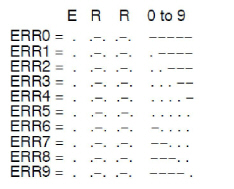
To Display Alarm Codes:
a.While in the Default Display mode, press the ALARM LIST key. This accesses the Alarm List Display Mode, which displays any alarms archived in the Alarm Queue.
b.The alarm queue stores up to 16 alarms in the sequence in which they occurred. The user may scroll through the list by depressing an ARROW key.
c.The left display will show “AL##,” where ## is the alarm number sequentially in the queue.
d.The right display will show the actual alarm code. “AA##” will display for an active alarm, where “##” is the alarm code. Or “IA##” will display for an inactive alarm.
e.“END” is displayed to indicate the end of the alarm list if any alarms are active.
f.“CLEAr” is displayed if all alarms are inactive. The alarm queue may then be cleared by pressing the ENTER key. The alarm list will clear and “-----” will be displayed.
AL26 is active when all of the sensors are not responding. Check the connector at the back of the controller, if it is loose or unplugged, reconnect it. Then run a pretrip test (P5) to clear AL26.
Pre-trip diagnostics is an independent controller function that will suspend normal refrigeration controller activities and provide preprogrammed test routines. The test routines include Auto Mode testing, which automatically performs a pre-programmed sequence of tests or Manual Mode testing, which allows the operator to select and run any of the individual tests.
Pre-trip inspection should not be performed with critical temperature cargoes in the container.
When Pre-Trip key is pressed, dehumidification and bulb mode will be deactivated. At the completion of Pre-Trip activity, dehumidification and bulb mode must be reactivated.
Testing may be initiated by use of the keypad or via communication, but when initiated by communication, the controller will execute the entire battery of tests (auto mode).
At the end of a pre-trip test, the message “P,” “rSLts” (pretest results) will be displayed. Pressing ENTER will allow the user to see the results for all subtests. The results will be displayed as “PASS” or “FAIL” for all the tests run to completion.
A detailed description of the pre-trip tests and test codes is provided in Table 4–7. Detailed operating instructions are provided in Section 5.9.
The Carrier Transicold “DataCORDER” software is integrated into the controller and serves to eliminate the temperature recorder and paper chart. DataCORDER functions may be accessed by keypad selections and viewed on the display module. The unit is also fitted with interrogation connections (see Figure 4.1), which may be used with the Carrier Transicold DataReader to download data. A personal computer with Carrier Transicold DataLINE software may also be used to download data and configure settings.
The resulting file uses a proprietary file format that protects it from potential tampering or altering of data. Therefore, once downloaded, all dcx files shall be considered secured. The DataCORDER consists of:
•Configuration Software
•Operational Software
•Data Storage Memory
•Real Time Clock (with internal battery backup)
•Six Thermistor Inputs
•Interrogation Connections
•Power Supply (battery pack)
The DataCORDER performs the following functions:
a.Logs data at 15, 30, 60 or 120 minute intervals and stores two years’ of data (based on one hour interval).
b.Records and displays alarms on the display module.
c.Records results of Pre-trip testing.
d.Records DataCORDER and temperature control software generated data and events as follows:
•Container ID Change
•Software Upgrades
•Alarm Activity
•Battery Low (Battery Pack)
•Data Retrieval
•Defrost Start and End
•Dehumidification Start and End
•Power Loss (with and without battery pack)
•Power Up (with and without battery pack)
•Remote Probe Temperatures in the Container (USDA cold treatment and cargo probe recording)
•Return Air Temperature
•Set Point Change
•Supply Air Temperature
•Real Time Clock Battery (Internal) Replacement
•Real-Time Clock Modification
•Trip Start
•ISO Trip Header (When entered via Interrogation program)
•Economy Mode Start and End
•“Auto 1/Auto 2/Auto 3” Pre-trip Start and End
•Bulb Mode Start
•Bulb Mode changes
•Bulb Mode End
•USDA Trip Comment
•Humidification Start and End
•USDA Probe Calibration
•Fresh Air Vent Position
The DataCORDER Software is subdivided into Operational Software, Configuration Software, and the Data Memory.
a. Operational Software
The Operational Software reads and interprets inputs for use by the Configuration Software. The inputs are labeled Function Codes. There are 35 function codes (see Table 4–8), which the operator may access to examine the current input data or stored data. To access these codes, do the following:
1.Press the ALT. MODE and CODE SELECT keys.
2.Press an arrow key until the left window displays the desired code number. The right window will display the value of this item for five seconds before returning to the normal display mode.
3.If a longer time is desired, press the ENTER key to extend the time to 30 seconds.
b. Configuration Software
The configuration software controls the recording and alarm functions of the DataCORDER. Reprogramming to the factory-installed configuration is achieved via a configuration card. Changes to the software may be made using the DataLINE integration software.
A list of the configuration variables is provided in Table 4–2. Descriptions of DataCORDER operation for each variable setting are provided in the following paragraphs.
4.8.3Sensor Configuration (dCF02)
Two modes of operation may be configured, the Standard Mode and the Generic Mode.
a. Standard Mode
In the standard mode, the user may configure the DataCORDER to record data using one of seven standard configurations. The seven standard configuration variables, with their descriptions, are listed in Table 4–3.
The six thermistor inputs (supply, return, USDA #1, #2, #3, and cargo probe) and the humidity sensor input will be generated by the DataCORDER. An example of a report using a standard configuration is shown in Figure 4.11.
The DataCORDER software uses the supply and return recorder sensors. The temperature control software uses the supply and return temperature sensors.
b. Generic Mode
The generic recording mode allows user selection of the network data points to be recorded. The user may select up to a total of eight data points for recording. A list of the data points available for recording follows. Changing the configuration to generic and selecting which data points to record may be done using the Carrier Transicold Data Retrieval Program.
1.Control mode
2.Control temperature
3.Frequency
4.Humidity
5.Phase A current
6.Phase B current
7.Phase C current
8.Main voltage
9.Suction modulation valve percentage
10.Discrete outputs (See Note)
11.Discrete inputs (See Note)
12.Ambient sensor
13.Compressor suction sensor
14.Compressor discharge sensor
15.Return temperature sensor
16.Supply temperature sensor
17.Defrost temperature sensor
18.Discharge pressure transducer
19.Suction pressure transducer
20.Condenser pressure transducer
The user may configure four time intervals between data recordings. Data is logged at exact intervals in accordance with the real-time clock. The clock is factory set at Greenwich Mean Time.
4.8.5Thermistor Format (dCF04)
The user may configure the format in which the thermistor readings are recorded. The low resolution is a 1 byte format and the normal resolution is a 2 byte format. The low resolution requires less memory and records temperature in 0.25°C (0.45°F) increments when in perishable mode or 0.5°C (0.9°F) increments when in the frozen mode. The normal resolution records temperature in 0.01°C (0.02°F) increments for the entire range.
Figure 4.11 Standard Configuration Report
4.8.6Sampling Type (dCF05 & dCF06)
Three types of data sampling are available - average, snapshot, and USDA. When configured to average, the average of readings taken every minute over the recording period is recorded. When configured to snapshot, the sensor reading at the log interval time is recorded. When USDA is configured, the supply and return temperature readings are averaged and the three USDA probe readings are snapshot.
4.8.7Alarm Configuration (dCF07 − dCF10)
The USDA and cargo probe alarms may be configured to OFF, ON or AUTO.
If a probe alarm is configured to OFF, then the alarm for this probe is always disabled.
If a probe alarm is configured to ON, then the associated alarm is always enabled.
If the probes are configured to AUTO, they act as a group. This function is designed to assist users who keep their DataCORDER configured for USDA recording, but do not install the probes for every trip. If all the probes are disconnected, no alarms are activated. As soon as one of the probes is installed, then all of the alarms are enabled and the remaining probes that are not installed will give active alarm indications.
The DataCORDER will record the initiation of a pre-trip test (refer to Section 4.7) and the results of each of the tests included in pre-trip. The data is time-stamped and may be extracted via the Data Retrieval program. Refer to Table 4–9 for a description of the data stored in the DataCORDER for each corresponding pre-trip test.
The DataCORDER may be powered up in any one of four ways:
1.Normal AC power: The DataCORDER is powered up when the unit is turned on via the stop-start switch.
2.Controller DC battery pack power: If a battery pack is installed, the DataCORDER will power up for communication when an interrogation cable is plugged into an interrogation receptacle.
3.External DC battery pack power: A 12-volt battery pack may also be plugged into the back of the interrogation cable, which is then plugged into an interrogation port. No controller battery pack is required with this method.
4.Real-time Clock demand: If the DataCORDER is equipped with a charged battery pack and AC power is not present, the DataCORDER will power up when the real-time clock indicates that a data recording should take place. When the DataCORDER is finished recording, it will power down.
During DataCORDER power-up, while using battery-pack power, the controller will perform a hardware voltage check on the battery. If the hardware check passes, the Controller will energize and perform a software battery voltage check before DataCORDER logging. If either test fails, the real-time clock battery power-up will be disabled until the next AC power cycle. Further DataCORDER temperature logging will be prohibited until that time.
An alarm will be generated when the battery voltage transitions from good to bad indicating that the battery pack needs recharging. If the alarm condition persists for more than 24 hours on continuous AC power, the battery pack needs replacement.
The DataCORDER will record the initiation of a Pre-trip test (refer to Section 4.7) and the results of each of the tests included in pre-trip. The data is time-stamped and may be extracted via the Data Retrieval program. Refer to Table 4–9 for a description of the data stored in the DataCORDER for each corresponding pre-trip test.
4.8.10DataCORDER Communications
Data retrieval from the DataCORDER can be accomplished by using the DataReader, DataLINE, DataBANK Card, or a communications interface module.
A DataReader, DataLine/DataView, or a communications interface module display of Communication Failed is caused by faulty data transfer between the DataCORDER and the data retrieval device. Common causes include:
1.Bad cable or connection between DataCORDER and data retrieval device.
2.PC communication port(s) unavailable or mis-assigned.
3.Chart Recorder Fuse (FCR) blown.
Communication identification for the models covered herein may be obtained on the Container Products Group Information Center by authorized Carrier Transicold Service Centers.
a. DataReader
The Carrier Transicold Data Reader (see Figure 4.12) is a simple to operate hand held device designed to extract data from the DataCORDER and upload it to a PC. The Data Reader has the ability to store multiple data files. Refer to Data Retrieval manual 62-10629 for a more detailed explanation of the DataReader.
- - - - -
b. DataBANK™ Card
The DataBANK™card is a PCMCIA card that interfaces with the controller through the programming slot and can download data at a much faster rate when compared to the PC or DataReader. Files downloaded to the DataBANK card files are accessible through an Omni PC Card Drive. The files can then be viewed using the DataLine software.
c. DataLine
The DataLINE software for a personal computer is supplied on both floppy disks and CD. This software allows interrogation, configuration variable assignment, screen view of the data, hard copy report generation, cold treatment probe calibration, and file management. Refer to Data Retrieval manual 62-10629 for a more detailed explanation of the DataLINE interrogation software. The DataLine manual may be found on the Internet at www.container.carrier.com.
d. Communications Interface Module
The communications interface module is a slave module which allows communication with a master central monitoring station. The module will respond to communication and return information over the main power line. With a remote monitoring unit installed, all functions and selectable features that are accessible at the unit may be performed at the master station. Retrieval of all DataCORDER reports may also be performed. Refer to the master system technical manual for further information.
Sustained cold temperature has been employed as an effective post harvest method for the control of Mediterranean and certain other tropical fruit flies. Exposing infested fruit to temperatures of 2.2°C (36°F) or below for specific periods results in the mortality of the various stages of this group of insects.
In response to the demand to replace fumigation with this environmentally sound process, Carrier has integrated Cold Treatment capability into its microprocessor system. These units have the ability to maintain supply air temperature within one-quarter degree Celsius of setpoint and record minute changes in product temperature within the DataCORDER memory, thus meeting USDA criteria. Information on USDA is provided in the following sub-paragraphs.
a. USDA Recording
A special type of recording is used for USDA cold treatment purposes. Cold treatment recording requires three remote temperature probes be placed at prescribed locations in the cargo. Provision is made to connect these probes to the DataCORDER via receptacles located at the rear left-hand side of the unit. Four or five receptacles are provided. The four three-pin receptacles are for the probes and fifth, five-pin, receptacle is the rear connection for the Interrogator. The probe receptacles are sized to accept plugs with tricam coupling locking devices. A label on the back panel of the unit shows which receptacle is used for each probe.
The standard DataCORDER report displays the supply and return air temperatures. The cold treatment report displays USDA #1, #2, #3, and the supply and return air temperatures. Cold treatment recording is backed up by a battery so recording can continue if AC power is lost.
b. USDA/ Message Trip Comment
A special feature is incorporated which allows the user to enter a USDA (or other) message at the head of a data report. The maximum message length is 78 characters. Only one message will be recorded per day.
4.8.12USDA Cold Treatment Procedure
The following is a summary of the steps required to initiate a USDA Cold Treatment:
a.Calibrate the three USDA probes by ice bathing the probes and performing the calibration function with the DataReader or a personal computer. This calibration procedure determines the probe offsets and stores them in the controller for use in generating the cold treatment report. Refer to the Data Retrieval manual 62-10629 for more details.
b.Pre-cool the container to the treatment temperature or below.
c.Install the DataCORDER module battery pack (if not already installed).
d.Place the three probes. The probes are placed into the pulp of the fruit (at the locations defined in the following table) as the product is loaded.
Sensor 1 |
Place in pulp of the product located next to the return air intake. |
Sensor 2 |
Place in pulp of the product five feet from the end of the load for 40-foot containers, or three feet from the end of the load for 20-foot containers. This probe should be placed in a center carton at one-half the height of the load. |
Sensor 3 |
Place in pulp of product five feet from the end of the load for 40-foot containers or three feet from the end of the load for 20-foot containers. This probe should be placed in a carton at a side wall at one-half the height of the load. |
e.To initiate USDA recording, connect the personal computer and perform the configuration as follows:
1.Enter ISO header information.
2.Add a trip comment if desired.
3.Configure for five probes (s, r, P1, P2, P3).
4.Configure for one-hour logging interval.
5.Set the sensor configuration at USDA.
6.Configure for two byte memory storage format.
7.Perform a “trip start.”
Alarm display is an independent DataCORDER function. If an operating parameter is outside of the expected range or a component does not return the correct signals back to the DataCORDER an alarm is generated. The DataCORDER contains a buffer of up to eight alarms. A listing of the DataCORDER alarms is provided in Table 4–10. Refer to Section 4.8.7 for configuration information.
To display alarm codes:
a.While in the Default Display mode, press the ALT. MODE & ALARM LIST keys. This accesses the DataCORDER Alarm List Display Mode, which displays any alarms stored in the Alarm Queue.
b.To scroll to the end of the alarm list, press the UP ARROW. Depressing the DOWN ARROW key will scroll the list backward.
c.The left display will show “AL#” where # is the alarms number in the queue. The right display will show “AA##,” if the alarm is active, where ## is the alarm number. “IA##,” will show if the alarm is inactive.
d.“END” is displayed to indicate the end of the alarm list if any alarms are active. “CLEAr” is displayed if all the alarms in the list are inactive.
e.If no alarms are active, the Alarm Queue may be cleared. The exception to this rule is the DataCORDER Alarm Queue Full alarm (AL91), which does not have to be inactive in order to clear the alarm list. To clear the alarm list:
1.Press the ALT. MODE & ALARM LIST keys.
2.Press the UP/DOWN ARROW key until “CLEAr” is displayed.
3.Press the ENTER key. The alarm list will clear and “-----” will be displayed.
4.Press the ALARM LIST key. “AL” will show on the left display and “-----” on the right display when there are no alarms in the list.
5.Upon clearing of the Alarm Queue, the Alarm light will be turned off.
DataLINE provides the user with an interface to view/ modify current settings of the ISO trip header through the ISO Trip Header screen.
The ISO Trip Header screen is displayed when the user clicks on the “ISO Trip Header” button in the “Trip Functions” Group Box on the System Tools screen.
F9 function - Provides the user with a shortcut for manually triggering the refresh operation. Before sending modified parameter values, the user must ensure that a successful connection is established with the controller.
If the connection is established with the DataCORDER, the current contents of the ISO Trip Header from the DataCORDER will be displayed in each field. If the connection is not established with the DataCORDER, all fields on the screen will be displayed as “Xs.” If at any time during the display of the ISO Trip Header screen the connection is not established or is lost, the user is alerted to the status of the connection.
After modifying the values and ensuring a successful connection has been made with the DataCORDER, click on the “Send” button to send the modified parameter values.
The maximum allowed length of the ISO Trip Header is 128 characters. If the user tries to refresh the screen or close the utility without sending the changes made on the screen to the DataCORDER, the user is alerted with a message.
4.9Controller Configuration Variables
Note: Configuration numbers not listed are not used in this application. These items may appear when loading configuration software to the controller but changes will not be recognized by the controller programming.
Code # |
Title |
Description |
|---|---|---|
Note: If the function is not applicable, the display will read “-----” |
||
Display Only Functions − Cd01 through Cd26 are display only functions. |
||
Cd01 |
Suction Modulation Valve (SMV) Opening (%) |
Displays the SMV percent open. The right display reads 100% when the valve is fully open and 0% when the valve is fully closed. The valve will usually be at 21% on start up of the unit except in very high ambient temperatures. |
Cd02 |
Quench Valve State |
Displays the state of the solenoid quench valve, open or closed. |
Cd03 |
Suction Solenoid Valve State |
Displays the state of the suction solenoid valve, open or closed. |
Cd04
Cd05
Cd06 |
Line
Current, Line
Current, Line
Current, |
The current sensor measures current on two legs. The third unmeasured leg is calculated based on a current algorithm. The current measured is used for control and diagnostic purposes. For control processing, the highest of the Phase A and B current values is used for current limiting purposes. For diagnostic processing, the current draws are used to monitor component energization. Whenever a heater or a motor is turned ON or OFF, the current draw increase/reduction for that activity is measured. The current draw is then tested to determine if it falls within the expected range of values for the component. Failure of this test will result in a pretrip failure or a control alarm indication. |
Cd07 |
Main Power Voltage |
The main supply voltage is displayed. |
Cd08 |
Main Power Frequency |
The value of the main power frequency is displayed in Hertz. The frequency displayed will be halved if either fuse F1 or F2 is bad (see alarm code AL21). |
Cd09 |
Ambient Air Temperature |
The Ambient Temperature Sensor reading is displayed. |
Cd10 |
Compressor Suction Temperature |
The Compressor Suction Temperature Sensor reading is displayed. |
Cd11 |
Compressor Discharge Temperature |
The Compressor Discharge Temperature Sensor reading is displayed. |
Cd12 |
Compressor Suction Port Pressure |
The Compressor Suction Pressure Transducer reading is displayed. |
Cd13 |
Condenser Pressure Control (CPC) Sensor |
The Condenser Pressure Control Sensor reading is displayed. |
Cd14 |
Compressor Discharge Pressure |
The Compressor Discharge Pressure Transducer reading is displayed. |
Cd15 |
Unloader Valve (On-Off) |
Not used in this application |
Cd16 |
Compressor Motor Hour Meter / Switch On Time |
Records total hours of compressor run time. Total hours are recorded in increments of 10 hours (i.e., 3000 hours is displayed as 300). / Press 'Enter' to display Start Switch 'ON' time. |
Cd17 |
Relative Humidity (%) |
Humidity sensor reading is displayed. This code displays the relative humidity, as a percent value. |
Cd18 |
Software Revision # |
The software revision number is displayed. |
Cd19 |
Battery Check |
This code checks the Controller/DataCORDER battery pack. While the test is running, “btest” will flash on the right display, followed by the result. PASS will be displayed for battery voltages greater than 7.0 volts. FAIL will be displayed for battery voltages between 4.5 and 7.0 volts, and ----- will be displayed for battery voltages less than 4.5 volts. After the result is displayed for four seconds, “btest” will again be displayed, and the user may continue to scroll through the various codes. |
Cd20 |
Config/Model # |
This code indicates the dash number of the model for which the Controller is configured (i.e., if the unit is a 69NT40-541-100, the display will show “41100”). To display controller configuration database information, press ENTER. Values in “CFYYMMDD” format are displayed if the controller was configured with a configuration card or with a valid OEM serial port configuration update; “YYMMDD” represents the publication date of the model configuration database. |
Cd21 |
ML2i - Humidity Water Pump/Atomizer Status |
This code displays the status of the humidity water pump (-----, FWD, REV or OFF). If not configured, the mode is permanently deactivated and will display -----. |
ML3 - Humidity Water Pump/Air Pump Status |
This code displays the status of the humidity water pump (-----, On, or OFF). If not configured, the mode is permanently deactivated and will display -----. |
|
Cd22 |
Compressor State |
The status of the compressor is displayed (high, low or off). |
Cd23 |
Evaporator Fan State |
Displays the current evaporator fan state (high, low or off). |
Cd24 |
Controlled Atmosphere State |
Displays the controlled atmosphere state (-----, On or Off). |
Cd25 |
Time Remaining Until Defrost |
This code displays the time remaining until the unit goes into defrost (in tenths of an hour). This value is based on the actual accumulated compressor running time. |
Cd26 |
Defrost Temperature Sensor Reading |
Defrost Temperature Sensor (DTS) reading is displayed. |
Configurable Functions |
||
Configurable Functions − Cd27 through Cd37 are user-selectable functions. The operator can change the value of these functions to meet the operational needs of the container. |
||
Cd27 |
Defrost Interval (Hours or Automatic) |
There are two modes for defrost initiation, either user-selected timed intervals or automatic control. The user-selected values are (OFF), 3, 6, 9, 12, 24 hours, AUTO, or PuLS. Factory default is 3 hours. Automatic defrost starts with an initial defrost at three hours and then adjusts the interval to the next defrost based on the accumulation of ice on the evaporator coil. Following a startup or after termination of a defrost, the time will not begin counting down until the defrost temperature sensor (DTS) reading falls below set point. If the reading of DTS rises above set point any time during the timer count down, the interval is reset and the countdown begins over. If the DTS fails, alarm code AL60 is activated and control switches over to the return temperature sensor. The controller will act in the same manner as with the DTS except the return temperature sensor reading will be used. If CnF23 is configured to “SAv” (save), then the value of the defrost interval timer will be saved at power down and restored at power up. This option prevents short power interruptions from resetting an almost expired defrost interval, and possibly delaying a needed defrost cycle. NOTE The defrost interval timer counts only during compressor run time. Configuration variable (CnF11) determines whether the operator will be allowed to chose “OFF” as a defrost interval option. Configuration variable (CnF64) determines whether the operator will be allowed to choose “PuLS” as a defrost interval option. For units operating with “PuLS” selected, defrost interval is determined by the unit temperature setpoint and the Evaporator Fan Pulsing Temperature Setting (Cd60). When the unit temperature setpoint is equal to or less than the Evaporator Fan Pulsing Temperature Setting, the defrost interval is set to 6 hours. Otherwise, the defrost interval is determined using the Automatic Defrost Interval Determination logic. In either case, “PuLS” remains displayed in this function select code. After a new Defrost Interval is selected, the previously selected Interval is used until the next defrost termination, the next time the DTT contacts are OPEN, or the next time power to the control is interrupted. If the previous value or the new value is “OFF”, the newly selected value will be used immediately. If any Auto Pretrip sequence is initiated, Cd27 will be set to 'AUTO' unless CnF49 (OEM Reset) is set to “Custom” AND CnF64 (Evaporator Fan Pulsing Logic) con figuration variable is set to IN, in which case Cd27 will be set to “PuLS”. |
Cd28 |
Temperature Units (Degrees C or Degrees F) |
This code determines the temperature units (°C or °F) which will be used for all temperature displays. The user selects °C or °F by selecting function code Cd28 and pushing the ENTER key. The factory default value is Celsius units. This function code will display “-----” if CnF34 is set to °F. |
Cd29 |
Failure Action Mode |
This is the desired action to be taken if an alarm occurs that severely limits the capability of the control system. Depending upon what alarm has occurred, the actual action taken may not be the same as the desired failure action. The user selects one of four possible actions as follows: A - Full Cooling (stepper motor SMV at maximum allowed opening) B - Partial Cooling (stepper motor SMV 11% open) C - Evaporator Fan Only D - Full System Shutdown - Factory Default |
Cd30 |
In-Range Tolerance |
The in-range tolerance will determine the band of temperatures around the set point which will be designated as in-range. For normal temperature control, control temperature is considered in range if it is within setpoint In-Range Tolerance. There are four possible values: 1 = +/- 0.5°C (+/-0.9°F) 2 = +/- 1.0°C (+/-1.8°F) 3 = +/- 1.5°C (+/-2.7°F) 4 = +/- 2.0°C (+/-3.6°F) - Factory Default If the control temperature is in-range, the IN-RANGE light will be illuminated. In-Range tolerance shall be set to +/- 2.0°C upon activation of dehumidification or bulb mode (Cd33, Cd35, Cd48). When CCPC is actively controlling, IN-RANGE TOLERANCE is not considered. “-----” will be displayed whenever Dehumidification or Bulb mode is enabled or when CCPC with six hour re-activation is actively controlling. “-----” will be displayed whenever Frozen Economy Mode is operating. |
Cd31 |
Stagger Start Offset Time (Seconds) |
The stagger start offset time is the amount of time that the unit will delay at start-up, thus allowing multiple units to stagger their control initiation when all units are powered up together. The eight possible offset values are: 0 (Factory Default), 3, 6, 9, 12, 15, 18 or 21 seconds |
Cd32 |
System Current Limit (Amperes) |
The current limit is the maximum current draw allowed on any phase at any time. Limiting the unit's current reduces the load on the main power supply. This is accomplished by reducing the SMV position until current draw is reduced to the set point. When desirable, the limit can be lowered; however, capacity is also reduced. The five values for 460VAC operation are 15, 17, 19, 21 (Factory Default), 23. |
Cd33 |
Humidity Setpoint |
This is the value in percent to which the system will dehumidify or humidify. There are configuration variables that determine whether dehumidification / humidification capabilities are installed. In the test mode, the setpoint will be temporarily set to 1%, allowing the test of dehumidification. After 5 minutes, the normal setpoint is restored. If unit is configured for HUMIDIFICATION MODE then selection of a setpoint greater than 75% will activate humidification, and a setpoint less than or equal to 75% will activate dehumidification. If the unit is configured for dehumidification only, then the entire setpoint range will apply to dehumidification. If Pretrip is initiated, this value will be set to “OFF” automatically. (Replaced by Cd48 if CnF50, Enhanced Bulb Mode, is active.) |
Cd34 |
Economy Mode |
The current state of the economy mode option, “-----”, On, or Off. CnF22 determines whether economy mode offered. Economy mode is a user selectable mode of operation provided for power saving purposes. |
Cd35 |
Bulb Mode |
The current state of the bulb mode option, “-----”, nOr, or bULb. (Replaced by Cd48 if CnF50, Enhanced Bulb Mode, is active.) Bulb mode is an extension of dehumidification control (Cd33). If dehumidification (CnF04) is set to “Off”, Cd35 will display “Nor” and the user will be unable to change it. CnF28 determines whether the bulb mode selection is offered. After a dehumidification set point has been selected and entered for code Cd33, the user may then change Cd35 to bulb. After Bulb Mode has been selected and entered, the user may then utilize function codes Cd36 and Cd37 to make the desired changes. |
Cd36 |
Evaporator Fan Speed Select |
This is the desired evaporator fan speed for use during the bulb Dehumidification and Humidification mode option. (Replaced by Cd48 if CnF50, Enhanced Bulb Mode, is active.) This code is enabled only if in the dehumidification mode (Cd33) and bulb mode (Cd35) has been set to “bulb”. If these conditions are not met, “alt” will be displayed (indicating that the evaporator fans will alternate their speed) and the display cannot be changed. If a dehumidification set point has been selected along with bulb mode then alt may be selected for alternating speed, “Lo” for low speed evaporator fan only, or “Hi” for high speed evaporator fan only. If a setting other than “alt” has been selected and bulb mode is deactivated in any manner, then selection reverts back to “alt”. |
Cd37 |
Variable DTT Setting (Bulb Mode) |
This is the Variable Defrost Termination Thermostat (DTT) setting to be used with the optional bulb mode functionality. This item is only displayed if the bulb mode option is configured on. (Replaced by Cd48 if CnF50, Enhanced Bulb Mode, is active.) |
Display Only Functions − Cd38 through Cd40 are display only functions. |
||
Cd38 |
Secondary Supply Temperature Sensor |
Code Cd38 will display the current supply recorder sensor (SRS) reading for units configured for four probes. If the unit is configured with a DataCORDER, Cd38 will display “-----”. If the DataCORDER suffers a failure (AL55), Cd38 will display the supply recorder sensor reading. |
Cd39 |
Secondary Return Temperature Sensor |
Code Cd39 will display the current return recorder sensor (RRS) reading for units configured for four probes. If the unit is configured with a DataCORDER, Cd39 will display “-----”. If the DataCORDER suffers a failure (AL55), Cd39 will display the return recorder sensor reading. |
Cd40 |
Container Identification Number |
If a valid container id exists, the default display for cd40 will be “cd40_XXXXX” where “XXXXX” is the 5th character through the 9th character of the container id. Pressing the Enter key on cd40 will display “id_YYYYYYY” where “YYYYYYY” is the 5th character to the 11th character of the container id. If no valid container id exists or the container id is blank, the default display will have cd40 on the left display and the right display will alternate between “_nEEd” and “___id”. Pressing the enter key while on cd40 in the state will prompt the Set Id Interface. On start up if the container id is not valid, cd40 be brought up on the display for the first minute of power up. This can be left by either entering a container id or leaving the code select normally. Code Cd40 is configured at commissioning to read a valid container identification number. The reading will not display alpha characters; only the numeric portion of the number will display. |
Cd41 |
Valve Override |
SERVICE FUNCTION: This code is used for troubleshooting, and allows manual positioning of the SMV. Refer to Section 7.20 for operating instructions. |
Configurable Functions − Cd43 is a user-selectable function. The operator can change the value of this function to meet the operational needs of the container. |
||
Cd43 |
AutoFresh Mode |
Cd43 is a user selectable mode of operation that allows opening and closing of a mechanical air vent door via a stepper motor. Selection modes are as follows: OFF - Air makeup vent will remain closed. USER - Allows for manual selection of the setting. DELAY - The opening of the door is based on selected time, return temperature and flow rate (percent opened). gASLM - The opening is based percent open and CO2 and O2 selectable limits (LM). This selection is only active if the unit has a CO2 sensor. TEST / CAL (CO2 sensor option units only) - The door will fully open and close to allow the user to inspect its operation. If CAL is selected, the controller will zero calibrate the CO2 sensor input. If the unit is not configured with AutoFresh, the CD43 will display “----” |
Display Only Function − Cd44 is a display only function. |
||
Cd44 |
eAutoFresh Values / CO2 Sensor Status |
Code Cd44 displays the eAutoFresh CO2 and O2 values (CO2 and O2) and CO2 and O2 limits (CO2 LIM and O2 LIM), respectively. This function code will be dashed out if not configured for eAutofresh. This function code will be dashed if CO2 sensor is not detected, and a sensor is not expected (didn't have one previously). This function code will display ChECK if a CO2 sensor has not been auto-detected at the most recent power-up and was detected at a previous power-up. If “ChECK” is displayed and the ENTER key is pressed, “SEnSr” is displayed with the choices of “YES” and “no”: “YES” - sensor should be remembered as detected (present) “no” - sensor should not be remembered as being detected (not present) |
Configurable Functions − Cd45 through Cd48 are user-selectable functions. The operator can change the value of these functions to meet the operational needs of the container. |
||
Cd45 |
Vent Position Sensor (VPS) Position |
Values: 0 to 240 for UPPER / 0 to 225 for LOWER This function code will be dashed out if not configured for VPS. When configured for VPS, Cd45 displays the current vent position in units of 5 CMH (units displayed as “CM”) or CFM (units displayed as “CF”) depending on the selection of Cd46 (Airflow display units), Cd28 (Metric/Imperial) or the pressing of the deg C/F key. Cd45 will display whenever the control detects movement via the sensor unless AL50 is active. Cd45 will display for 30 seconds, then time out and return to the normal display mode. |
Cd46 |
Airflow Display Units |
Selects the airflow units to be displayed by Cd45 if configured for Vent Position Sensor or displayed by USER/FLO under Cd43 if configured for Autoslide. CF = Cubic Feet per Minute CM = Cubic Meters per Hour bOth = Displays CF or CM depending on the setting of Cd28 (Metric/Imperial) or the pressing of the degree C/F key. |
Cd47 |
Variable Economy Temperature Setting |
The variable temperature “degrees C or degrees F” setting is used with economy mode. Function code is −−−− when unit is not configured for economy mode. |
Cd48 |
Dehumidification / Bulb Cargo Mode Parameter Selection |
Initially Cd48 will display current dehumidification mode ; bUlb - bulb cargo mode, dEhUM - normal dehumidification, or OFF - off. This display is steady. Pressing ENTER key will take the interface down into a hierarchy of parameter selection menus (mode, setpoint, evaporator speed, DTT setting). Pressing ENTER key in any parameter selection menu commits to selection of the currently displayed parameter and causes the interface to descend into the next parameter selection menu. All parameter selection menus alternate between a blank display and the current selection in the right hand display. Pressing CODE SELECT key in a selection menu cancels the current selection activity and ascends back up to the next higher selection menu (or to Cd48 display mode if that is the next higher). If the operator does not press any key for five seconds the interface reverts to normal system display and the current selection menu is cancelled, but any previously committed changes are retained. Available parameters and parameter ranges are a function of configuration options and previously selected parameters as indicated above. Whenever any pretrip test is initiated, dehumidification mode goes to OFF. Whenever dehumidification mode goes to OFF: •Dehumidification control setpoint goes to 0% RH internally but will then initialize to 95% RH when dehumidification-mode leaves OFF. •Evaporator speed select goes to Alt for units without PWM Compressor Control (Cnf57 = Out), Evaporator speed select goes to Hi for units with PWM Compressor Control (Cnf57 = In). •DTT setting goes to 25.6°C or 18.0°C, depending on Cnf41. Whenever dehumidification mode is set to bUlb, DTT setting goes to 18.0°C if it had been set higher. Whenever dehumidification mode is set to dEhUM, DTT setting goes to 25.6°C or 18.0°C, depending on Cnf41. For units without PWM Compressor Control (Cnf57 = Out): •Whenever dehumidification control setpoint is set below 65% RH evaporator speed select goes to LO if it had been set to Hi. •Whenever dehumidification control setpoint is set above 64% RH evaporator speed select goes to Alt if it had been set to LO. For units with PWM Compressor Control (Cnf57 = In): •Whenever dehumidification control set point is set below 60% RH, the evaporator fan speed is set to LO, the user has the ability to set the evaporator fan speed to Hi via the keypad. •Whenever dehumidification control set point is set equal to or above 60% RH, the evaporator fan speed is set to Hi, the user has the ability to set the evaporator fan speed to LO via the keypad. |
Display Only Function − Cd49 is a display only function. |
||
Cd49 |
Days Since Last Successful Pretrip |
Displays the number of days since last successful pretrip sequence. Press ENTER to view the number of days since the last successful pretrip for Auto1, Auto2, and Auto2 in sequence. Press CODE SELECT to step back through the list and ultimately to exit the Cd49 display. |
Configurable Functions − Cd50 through Cd53 are user-selectable functions. The operator can change the value of these functions to meet the operational needs of the container. |
||
Cd50 |
CCPC Enable/Disable |
“OFF” = disabled. “On” = enabled. “SEtPt” = suspended by setpoint too low. “CAHUM” = suspended by CA or humidity control. “ACt” = suspended by ACT active. “FAIL” = all return temperature probe failure for CCPC. “PrtrP” = pretrip active. “C LIM” = suspended by cool limit logic. “PULL” = pulldown active. “ALArM” = suspended by shutdown alarm Press enter, arrow keys, and then enter to select “OFF” or “On”. If “On” is selected, CCPC operation may be suspended as indicated by one of the suspension codes listed above. If CCPC is not “OFF” and is not suspended, “On” will be displayed. |
Cd51 |
Automatic Cold Treatment (ACT) Mode Parameter Selection |
ACT-mode: Cd51 increments of (1 day)_(1hr), Display: default “0_0” “done” mm-dd this will be display is ACT has completed “ACt” value On OFF or “----”Display /Select: default “OFF” “trEAt” value °C / °F on 0.1 degree increments Display/Select: default “0.0°C” “DAyS” value “0-99” increments of 1 Display/Select: default “0” “ProbE” value Probe positions ex '1 2 _ 4' '1 _ 3 _' Display: default “---- “ “SPnEW” value °C / °F on 0.1_ increments Display/Select: default “10.0°C” Initially Cd51 will display current countdown timer increments of (1 day)_(1hr), de fault “0_0” Pressing ENTER key will take the interface down into a hierarchy of parameter selection menus in the order listed above. Pressing ENTER key in any of the parameter selection menus commits to selection of the currently displayed parameter and causes the interface to descend into the next parameter selection menu. All parameter selection menus alternate between a blank display and the current selection in the right hand display. Pressing CODE SELECT key in a selection menu cancels the current selection activity and ascends back up to the next higher selection menu (or to Cd51 dis play mode if that is the next higher). If the operator does not press any key for five seconds the interface reverts to normal system display and the current selection menu is cancelled, but any previously committed changes are retained. Available parameters and parameter ranges are a function of configuration options and previously selected parameters as indicated above. Parameter with the exception of “Act” may not be altered if Cd51 is re-entered if “Act” is “On”. When ACT has completed including reaching the new setpoint “done” on the left display and the MONTH DAY of completion on the right display will be displayed as the second entry in the menu. Turning ACT off clears this entry. This action also resets Cd51 to initial time remaining. ACT must then be turned on to view or modify the additional parameters. Whenever any auto pretrip test or Trip Start is initiated, act-mode goes to OFF. |
Cd53 |
Automatic Set point Change (ASC) Mode Parameter Selection |
ASC-mode: Cd53 increments of (1 day)_(1hr), Display: default “0_0” “done” mm-dd this will be display is ASC has completed “ASC” value “On” “OFF” Display /Select: default “OFF” “nSC” value “1 - 6” (This is the value “n” for the subsequent entries). “SP (n-1)” value °C/°F on 0.1 degree increments Display/Select: default “10.0°C” “DAY (n-1)” value “1-99” increments of 1 Display/Select: default “1” “SP” (n) value °C/°F on 0.1 degree increments Display/Select: default “10.0°C” Initially displays current count down timer increments of (1 day)(1hr), default “0_0” Pressing ENTER key will take the interface down into a hierarchy of parameter selection menus in the order listed above. Pressing ENTER key in any of the parameter selection menus selects the currently displayed parameter and causes the interface to descend into the next parameter selection menu. All parameter selection menus alternate between a blank display and the current selection in the right hand display. Pressing CODE SELECT key in a selection menu cancels the current selection activity and ascends back up to the next higher selection menu (or to Cd53 dis play mode if that is the next higher). If the operator does not press any key for five seconds the interface reverts to normal system display and the current selection menu is cancelled, but any previously committed changes are retained. Available parameters and parameter ranges are a function of configuration options and previously selected parameters as indicated above. Parameter with the exception of “ASC” may not be altered if Cd53 is re-entered if “ASC” is “On”. When ASC has completed including reaching the last setpoint “done” on the left display and the MONTH DAY of completion on the right display will be displayed as the second entry in the menu. Turning ASC off clears this entry. This action also resets Cd53 to initial time remaining. ASC must then be turned on to view or modify the additional parameters. Whenever any auto Pretrip test or Trip Start is initiated, ASC mode goes to OFF. |
Display Only Functions − Cd55 through Cd58 are display only functions. |
||
Cd55 |
Discharge Superheat |
Cd55 will display the discharge superheat values in °C / °F as calculated by the discharge temperature minus the discharge saturation temperature as calculated from discharge pressure. “-----” will be displayed if selection is not valid. |
Cd58 |
Water Pressure Switch / Condenser Fan Switch State Override Logic State |
Cd58 will display “CLOSE” if the WPS or CFS switch contacts are closed or if these options are not installed. “OPEn” is displayed when the WPS or CFS switch contacts are open. When the WPS/CFS Override Logic is “TRUE”, the right display will flash on all units. 1.This CLOSE/OPEn state displayed in this Code Select function only applies to units that have the ability to detect the state of a WPS/CFS. This function should not be relied upon to display the condition of the switch on units that don’t have a WPS/CFS switch connected to ECG2 exclusively. 2.The right display will flash if the WPS/CFS Override Logic is TRUE on all units. This is always the case, whether the unit has a WPS or CFS installed or not. 3.The ability of the WPS/CFS Override Logic to control the condenser fan is limited. It is not possible for this logic to control the fan on units that have the WPS or CFS wired in series with the fan contactor. Units wired in this configuration can indicate that the WPS/CFS Override Logic is active by flashing the right display, however, the wiring will not allow for control of the condenser fan. |
Configurable Functions − Cd60 is a user-selectable function. The operator can change the value of this function to meet the operational needs of the container. |
||
Cd60 |
Evaporator Fan Pulsing Temperature Setting |
Cd60 contains a selectable temperature range used to determine the engagement point of the Evaporator Fan Pulsing logic. Default setting is -18.1°C. The user may change the temperature by pressing enter, then scrolling to the desired temperature using either arrow key. Press Enter to accept the change. The temperature setting will be retained until either a Pretrip or Trip Start is initiated at which time the temperature will set to the default setting. |
Figure 4.13 Alarm Troubleshooting Sequence
4.11Controller Alarm Indications
Table 4–6 Controller Alarm Indications
Alarm Code |
Cause |
Components |
Troubleshooting |
|---|---|---|---|
AL05 Manual Defrost Switch Failure |
Controller has detected continuous Manual Defrost Switch activity for five minutes or more. |
Keypad |
Power cycle the unit. Resetting the unit may correct problem, monitor the unit. If the alarm reappears after 5 minutes replace the keypad. |
AL06 Keypad or Keypad Harness Fail |
Controller has detected one of the keypad keys is continuously activity. |
Keypad or Harness |
Power cycle the unit. Resetting the unit may correct problem, monitor the unit. If the alarm reappears replace the keypad and harness. |
AL07 Fresh Air Vent Open |
The VPS is reading greater than 0 CMH while unit is in frozen mode or XtendFRESH active. |
Vent Position Sensor (VPS) |
Manually reposition vent and confirm using Cd45. Refer to VENT POSITION SENSOR SERVICE Section 7.25. If unable to obtain zero reading, replace defective VPS. |
AL10 CO2 Sensor Failure |
Alarm 10 is triggered when the CO2 sensor voltage is operating outside of the 0.9 v to 4.7 v range, or if the sensor is out of range. |
This is a display alarm and has no associated failure action. |
Refer to eAutoFresh manual. The alarm is triggered off when voltage is within operating range. |
AL11 Evaporator fan 1 IP |
Alarm 11 is triggered when configured for single evap operation and MC6 sensed high. |
Evaporator Fan 1 |
The unit will suspend probe check diagnostic logic and disable the probe check portion of defrost cycle. AL11 is triggered off when MC6 sensed low. |
AL12 Evaporator fan 2 IP |
Alarm 12 is triggered when configured for single evap operation and KB10 sensed high. |
Evaporator Fan 2 |
The unit will suspend probe check diagnostic logic and disable the probe check portion of defrost cycle. AL12 is triggered off when KB10 sensed low. |
AL15 Loss of cooling |
Unit fails to achieve 0.25°C temperature delta for eight minutes before a probe-check defrost and then fails again for thirty minutes after the probe-check. |
N/A |
Power cycle the unit. Resetting the unit may correct problem, monitor the unit. |
AL20 Control Contactor Fuse (F3) |
Control power fuse (F3A or F3B) is open. |
Check F3A, if the fuse is open: |
Check PA, PB, CH coils for short to ground, if short is found: Replace the defective coil. Replace the fuse. |
Check F3B, if the fuse is open: |
Check CF, ES, EF, HR coils for short to ground, if short is found, coil is defective. Replace the defective coil. Replace the fuse. |
||
Check Voltage at QC1: |
If voltage is present, it indicates a defective microprocessor. Refer to Controller Service Section 7.23. |
||
AL21 Control Circuit Fuse (F1/F2) |
One of the 18 VAC controller fuses (F1/F2) is open. Refer to Cd08. |
System Sensors |
Check system sensors for short to ground. Replace defective sensor(s). |
Wiring |
Check wiring for short to ground. Repair as needed. |
||
Controller |
Controller may have an internal short. Replace controller, refer to Controller Service Section 7.23. |
||
AL22 Evaporator IP |
Evaporator motor internal protector (IP) is open. |
Evaporator Motor |
Shut down unit, disconnect power, & check Evaporator Motor IP at plug connection pins 4 & 6. Replace defective evaporator fan motor, refer to EVAPORATOR FAN MOTOR Service Section 7.16. |
AL23 Loss of Phase B |
Controller fails to detect current draw. |
Incoming Power |
Check incoming power source. Correct power source as required. |
AL24 Compressor IP |
Compressor internal protector (IP) is open. |
Compressor |
Shut down unit disconnect power, & check resistance of compressor windings at contactor T1-T2, T2-T3. Monitor unit, if alarm remains active or is repetitive replace the compressor at the next available opportunity, refer to COMPRESSOR Service Section 7.8. |
AL25 Condenser IP |
Condenser fan motor internal protector (IP) is open. |
Insufficient Air Flow |
Shut down unit and check condenser fan for obstructions. Remove obstructions. |
Condenser Fan Motor |
Shut down unit, disconnect power, & check Condenser Fan Motor IP at plug connection pins 1 & 2. Replace defective condenser fan motor, refer to Condenser Fan Motor Assembly Service |
||
AL26 All Sensors Failure: Supply/Return Probes |
Sensors out of range. |
All sensors detected as out of range |
Perform Pre-trip P5: If P5 passes, no further action is required. If P5 fails, replace the defective sensor as determined by P5, refer to TEMPERATURE SENSOR Service Section 7.24. |
AL27 Analog to Digital Accuracy Failure |
Controller AD converter faulty. |
Controller |
Power cycle the unit. If the alarm persists, it indicates a defective microprocessor. Replace defective microprocessor, refer to Controller Service Section 7.23. |
AL29 AutoFresh Failure |
Alarm 29 is triggered if CO2 or O2 level is outside of the limit range and the vent position is at 100% for longer than 90 minutes. |
Alarm LED will be activated and user intervention is required. |
Refer to eAutoFresh manual. The alarm is triggered off when atmospheric conditions are within limit settings |
AL50 Air Vent Position Sensor (VPS) |
VPS Sensor out of range. |
Vent Position Sensor (VPS) |
Make sure VPS is secure. Manually tighten panel. |
If the alarm persists, replace the sensor or the assembly. Replace VPS. |
|||
AL51 EEPROM Failure |
Controller Memory Failure |
Controller |
Pressing the ENTER key when “CLEAr” is displayed will result in an attempt to clear the alarm. If action is successful (all alarms are inactive), alarm 51 will be reset |
Power cycle the unit. If the alarm persists, it indicates defective controller memory. Replace defective controller, refer to Controller Service Section 7.23. |
|||
AL52 EEPROM Alarm List Full |
Alarm list queue is full |
Active Alarms |
Repair any alarms in the queue that are active. Indicated by “AA”. Clear alarms, refer to CONTROLLER ALARMS Table 4–6. |
AL53 Battery Pack Failure |
Battery voltage low |
Battery |
If this alarm occurs on start up, allow a unit fitted with rechargeable batteries to operate for up to 24 hours to charge rechargeable batteries sufficiently. Once fully charged, the alarm will deactivate. To clear the alarm press ENTER and ALT simultaneously at the startup of Cd19 (Battery Check).
If alarm persists, replace the battery pack, refer to Section 7.23.5 Battery Replacement. |
AL54 Primary Supply Sensor (STS) |
Invalid Supply Temperature Sensor (STS) reading. |
Supply Temperature Sensor (STS) |
Perform Pre-trip P5: If P5 passes, no further action is required. If P5 fails, replace the defective sensor as determined by P5, refer to TEMPERATURE SENSOR Service Section 7.24. |
AL56 Primary Return Sensor (RTS) |
Invalid Return Temperature Sensor (RTS) reading. |
Return Temperature Sensor (RTS) |
Perform Pre-trip P5: If P5 passes, no further action is required. If P5 fails, replace the defective sensor as determined by P5, refer to TEMPERATURE SENSOR Service Section 7.24. |
AL57 Ambient Sensor (AMBS) |
Invalid Ambient Temperature Sensor (AMBS) reading. |
Ambient Temperature Sensor (AMBS) |
Test the AMBS, refer to TEMPERATURE SENSOR Service Section 7.24. Replace AMBS if defective, refer to TEMPERATURE SENSOR Service Section 7.24. |
AL58 Compressor High Pressure Safety (HPS) |
High pressure safety switch remains open for at least one minute. |
High Pressure Switch (HPS) |
Test the HPS; refer to Checking High Pressure Switch, Section 7.9.1. Replace HPS if defective, refer to High Pressure Switch, Section 7.9. |
Refrigeration System |
Check unit for air flow restrictions. Clean or remove any debris from coils. |
||
AL59 Heater Termination Thermostat (HTT) |
Heat Termination Thermostat (HTT) is open. |
Alarm 59 is triggered by the opening of the Heat Termination Thermostat (HTT) and will result in the disabling of the heater. |
Check for 24 volts at test point TP10, if no voltage at TP10 after unit has reached set point HTT is open. Replace HTT if defective. |
AL60 Defrost Temperature Sensor (DTS) |
Failure of the Defrost Temperature Sensor (DTS) to open. |
Defrost Temperature Sensor (DTS) |
Test the DTS; refer to Sensor Checkout Procedure Section 7.24.1. Replace the DTS if defective, refer to Sensor Replacement Section 7.24.2. |
AL61 Heater Current Draw Fault |
Improper current draw during heat or defrost mode. |
Heater(s) |
While in heat or defrost mode, check for proper current draw at heater contactors, refer to ELECTRICAL DATA Section 3.3. Replace heater(s) if defective, refer to Section 7.15.2 Evaporator Heater Removal and Replacement |
Contactor |
Check voltage at heater contactor on the heater side. If no voltage present: Replace heater contactor if defective. |
||
AL63 Current Limit |
Unit operating above current limit. |
Refrigeration System |
Check unit for air flow restrictions. Clean or remove any debris from coils. |
Check unit for proper operation. Repair as needed. |
|||
Power supply |
Confirm supply voltage / frequency is within specification and balanced according to ELECTRICAL DATA Section 3.3. Correct power supply. |
||
Current limit set too low |
Check current limit setting Code Cd32. The current limit can be raised (maximum of 23 amps) using Cd32. |
||
AL64 Discharge Temperature Sensor (CPDS) |
Discharge Temperature sensor out of range. |
Discharge temperature sensor (CPDS). |
Test the CPDS; refer to Sensor Checkout Procedure, Section 7.24.1. Replace the CPDS if defective, refer to Sensor Replacement Section 7.24. |
AL65 Discharge Pressure Transducer (DPT) |
Compressor Discharge Transducer is out of range. |
Compressor Discharge Transducer (DPT) |
Confirm accurate DPT pressure readings, refer to MANIFOLD GAUGE SET Section 7.2. Replace DPT if defective |
AL66 (SPT) Suction Pressure Transducer, (EPT) Evaporator Pressure Transducer |
Suction Pressure Transducer (SPT) out of range. |
Suction Pressure Transducer (SPT) |
Confirm accurate EPT and SPT pressure readings, refer to MANIFOLD GAUGE SET Section 7.2. - Performing a Pre-trip 5-9 test will also check the transducers. Replace EPT/SPT if defective. |
Monitor. If the alarm persists, it may indicate a failing compressor, refer to COMPRESSOR Service Section 7.8. |
|||
AL67 Humidity Sensor |
Humidity Sensor (HS) reading out of range. |
Humidity Sensor (HS) |
Make sure the humidity sensor is properly connected in the socket and the wires have not been damaged. Monitor, replace HS if alarm persists. |
AL68 CPC Pressure Sensor (PS3) |
Condenser Pressure Transducer (CPC) out of range. |
Condenser Pressure Transducer (CPC) |
NA. Unit will disable Condenser Pressure Control if Configured. |
AL69 Suction Temp Sensor (CPSS) |
Suction Temperature Sensor (CPSS) out of range. |
Suction Temperature Sensor (CPSS) |
Test the CPSS, refer to TEMPERATURE SENSOR Service Section 7.24. Replace CPSS if defective, refer to TEMPERATURE SENSOR Service Section 7.24. |
AL70 Secondary Supply Sensor (SRS) |
Secondary Supply Sensor (SRS) is out of range. |
Secondary Supply Sensor (SRS) |
Perform Pre-trip P5: If P5 passes, no further action is required. If P5 fails, replace the defective sensor as determined by P5, refer to TEMPERATURE SENSOR Service Section 7.24. |
AL71 Secondary Return Sensor (RRS) |
Secondary Return Sensor (RRS) is out of range. |
Secondary Return Sensor (RRS) |
Perform Pre-trip P5: If P5 passes, no further action is required. If P5 fails, replace the defective sensor as determined by P5, refer to TEMPERATURE SENSOR Service Section 7.24. |
AL72 Control Temp Out of Range |
After the unit goes in-range for 30 minutes then out of range for a continuous 120 minutes. |
Refrigeration System |
Ensure unit is operating correctly. Power cycle unit. Control Temperature is in In-range. Any Pre-trip mode, resets the timers. |
NOTE If the controller is configured for four probes without a DataCORDER, the DataCORDER alarms AL70 and AL71 will be processed as Controller alarms AL70 and AL71. Refer to Table 4–10. |
|||
ERR # |
Internal Microprocessor Failure |
The controller performs self-check routines. If an internal failure occurs, an “ERR” alarm will appear on the display. This is an indication the controller needs to be replaced. |
|
ERROR |
DESCRIPTION |
||
ERR 0-RAM failure |
Indicates that the controller working memory has failed. |
||
ERR 1-Program Memory failure |
Indicates a problem with the controller program. |
||
ERR 2-Watchdog time-out |
The controller program has entered a mode whereby the controller program has stopped executing. |
||
ERR 3-N/A |
N/A |
||
ERR 4-N/A |
N/A |
||
ERR 5-A-D failure |
The controller’s Analog to Digital (A-D) converter has failed. |
||
ERR 6-IO Board failure |
Internal program / update failure. |
||
ERR 7-Controller failure |
Internal version / firmware incompatible. |
||
ERR 8-DataCORDER failure |
Internal DataCORDER memory failure. |
||
ERR 9-Controller failure |
Internal controller memory failure. |
||
In the event that a failure occurs and the display cannot be updated, the status LED will indicate the appropriate ERR code using Morse code as shown below.
|
|||
Entr StPt |
Enter Set point (Press Arrow & Enter) |
The controller is prompting the operator to enter a set point. |
|
LO |
Low Main Voltage (Function Codes Cd27-38 disabled and NO alarm stored.) |
This message will be alternately displayed with the set point whenever the supply voltage is less than 75% of its proper value. |
|
4.12Controller Pre-Trip Test Codes