Carrier POD Setup Procedures
This document contains general guidelines for setting up a container as a Carrier Pod unit, for temperature-controlled mobile storage solutions. For additional actions, follow local requirements within the area of application.
This document contains instructions based on vaccine storage without dry ice. If dry ice is needed, further safety guidelines are required.
In no event will Carrier Transicold be liable for any direct, indirect, punitive, incidental, special, or consequential damages to property or life, whatsoever arising out of or connected with your failure to follow this procedure or misuse of the product. The user expressly understands and agrees to assume all risks for failure to follow this procedure. |
The following are required in order to setup a POD for cold storage:
•10 ft or 20 ft insulated shipping container
•3 phase, 50/60 Hz 380/460 VAC, 30-amp power supply
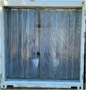
•Curtain installed at the end of the box
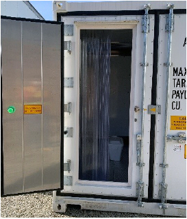
•Butcher door for fast, easy access in and out of the container. This is recommended, but not required.
Curtain
Butcher Door
Prepare the Pod for Proper Air Supply to Cargo
•For a 10 ft container box, no special preparation is needed.
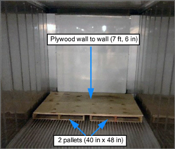
•For a 20 ft container box, add two standard pallets (40 in x 48 in) at the end of the unit, stacked side by side. Then, place a piece of plywood on top of the pallets for wall to wall coverage (approximately 7 ft, 6 in).
20 Ft Container Internal Layout Requirement
Choose a Layout for Cargo Loading
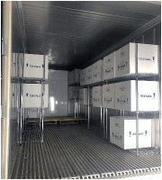
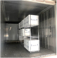
There are three recommended layout options for cargo loading in a 10 or 20 ft container. Options are based on the need to ensure proper air circulation and prevent conductive heat loss, and also allow easy access in loading / unloading cargo. For any option chosen, boxes must not come in contact with the container side wall.
Option 1: Two rows of metal shelves, one on each side of the container. This is the preferred option.
Option 2: One row of metal shelves offset from the side of the container, a minimum of 1 ft from the container wall.
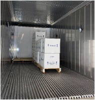
Option 3: One row of pallets offset from the side of the container, a minimum of 1 ft from the container wall. It may be difficult to manage first in / first out with this option due to boxes being stacked.
Option 1
Option 2
Option 3
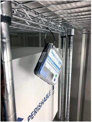
Sensitech TempTale temperature monitors must be installed in the Pod. The placement of monitors depends on the layout that is chosen for cargo loading. The monitors are to be shelf-mounted or wall-mounted.
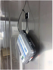
Wall-mounted monitors should be mounted at least 1/2” minimum from the side wall. Place a low temperature adhesive hook to the Pod wall and wire tie the temperature monitor to it using a wire tie wrap.
•Replace temperature monitors periodically (approximately 15 days).
•Install temperature monitors inside the vaccine boxes based on the manufacturer recommendations.
TempTale, Shelf-Mounted
TempTale, Wall-Mounted
Procedure for Layout Option 1, Two Rows of Shelves
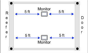
•For a 10 ft container - Place two shelf-mounted monitors across from each other, about 5 ft from the door.
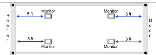
•For a 20 ft container - Four shelf-mounted monitors are required. Place two monitors across from each other, about 5 ft from the reefer unit. Place two monitors across from each other, about 5 ft from the door.
10 Ft Container, Top View
20 Ft Container, Top View
Procedure for Layout Option 2 or 3, One Row of Shelves or One Row of Pallets
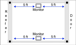
•For a 10 ft container - Place two wall-mounted temperature monitors along the container side wall (1/2” minimum from the wall) and across from each other. Each monitor will be about 5 ft from the door.
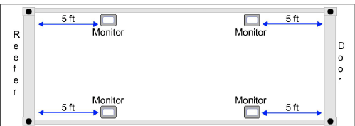
•For a 20 ft container - Four wall-mounted temperature monitors are required. Place all monitors along the container side wall (1/2” minimum from the wall). Place two monitors across from each other, about 5 ft from the reefer unit. Place two monitors across from each other, about 5 ft from the door.
10 Ft Container, Top View
20 Ft Container, Top View
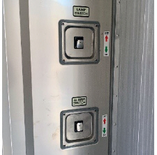
The following are options (not supplied) which can be added to the container to improve operation:
•Lamp Switch. Manual switch that improves visibility inside the container when handling sensitive cargo.
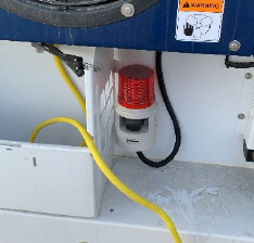
•Alarm Light Switch. Manual switch activating an external red alarm light. This is to protect a person that is unable to open the door from inside of the container.
•Door Switch. Manual switch at the butcher door to power off the refrigeration unit prior to a person entering the container. This prevents warm air from entering the container.
Lamp Switch / Alarm Light Switch
Alarm Light
The following items should be configured on the container unit:
•Install a TripLINK telematics device configured for monitoring cargo
•Change the controller configuration variable CnF41, Enable Low DTT Setting, from Out (78F) to In (64F)
•Establish a setpoint per manufacturer’s recommendation. For example, if the vaccine temperature range is (-25C to -15C), establish a setpoint of -23C to control to the low end of the temperature range but not exceed the manufacturer’s temperature specification.
•Set the controller function code Cd27, Defrost Interval, to 24 hours. Do not use the AUTO setting.
•Make sure that the Fresh Air Makeup Vent is closed
•Run a Pre-trip Auto 2 on the unit to perform a complete operational check of the unit. Verify that it has been successfully completed prior to loading.
It is recommended to store the cargo in the manufacturer’s packaging while being stored within the container in order to maintain tighter temperature control of the cargo within the package. If the cargo is removed from the manufacturer's packaging, it must be placed into an insulated container and surrounded by gel packs at the frozen temperature to maintain proper temperature during storage.
Do not store a vaccine package alone (no insulated container) inside the Pod.
Dry ice, required for setpoints lower than -35C, requires further safety requirements.
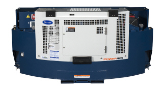
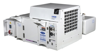
If land based 460 VAC / 60Hz or 390 VAC / 50 Hz power is not available, a Carrier RG or UG model generator set can be used to power the POD.
RG Generator Set
UG Generator Set
Either one of these models can be run by placing the generator set unit on the ground and connecting the refrigeration unit’s power cable to the generator set.
Before start up, both the generator set circuit breaker (CB-1) and the refrigerated unit should be off. After start up, the generator set unit should be run for at least two minutes to allow the power source to stabilize before supplying power to the refrigerated unit. This will eliminate the potential of any cold start transient spikes from reaching the refrigerated unit. Cold start transient spikes can potentially cause a nuisance over voltage alarms on refrigerated units that are sensitive to electrical spikes or transients.
When routing the refrigeration unit’s power to the genset, make sure that the cable is safely positioned to prevent users from crossing over the cable while also ensuring that all regional safety requirements are followed.
Beware of moving poly V-belt, belt driven components and hot exhaust components.
Under no circumstances should ether or any other unauthorized starting aids be used in conjunction with the air intake heater.
Piston rings in engines that have operated less than 100 hours may not be fully seated. This may lead to the possibility of oil seepage from the exhaust pipe. To properly seat the rings, operate the engine under full load for a period of 24 hours. If the condition persists, check valve clearance when the engine is cold.
Starting Instructions for a Generator Set Unit
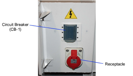
1.Make sure the generator set circuit breaker CB-1 is in the OFF position.
2.Hook up the 460 volt cable from the refrigerated unit to the generator set receptacle.
Circuit Breaker and Receptacle
Instructions for Standard Units:
a.Hold the INTAKE AIR HEATER switch in the PREHEAT position (See table below for suggested hold times). With the INTAKE AIR HEATER switch held in the PREHEAT position, place the IGNITION switch in the START position.
Ambient Temperatures |
Time |
|---|---|
26°C (78°F) |
5 seconds |
0°C to 26°C (32°F to 78°F) |
10 seconds |
-8°C to 26°C (18°F to 32°F) |
20 seconds |
Below -8°C (18°F) |
30 seconds |
INTAKE AIR HEATER and IGNITION switches
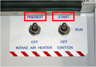
b.After the engine has started, release the IGNITION switch allowing it to return to the RUN position. Continue to hold the INTAKE AIR HEATER switch in the PREHEAT position until the engine develops sufficient oil pressure to close the Oil Pressure Safety Switch (approximately five seconds). When released, the INTAKE AIR HEATER switch will automatically return to the OFF position.
Instructions for Units with Auto Restart Option:
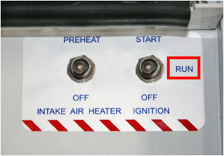
a.Place the IGNITION switch in the RUN position.
IGNITION switch
b.If the Low Coolant Sensor (LCS) is immersed in coolant, the Auto Restart Module will energize the heater for 30 seconds and the safety buzzer will sound. After the 30 second delay, the unit will attempt to start.
Post-Start Operating Instructions
1.Allow the generator set to run for at least two minutes.
2.Place the generator set circuit breaker CB-1 in the ON position.
3.Check generator output with a volt meter. Voltage output at start up with no load at 50Hz operation should be 1500 RPM, 360-460 VAC. Voltage output may vary and fall with ISO specifications based on ambient.
4.Once the generator set is running, turn on the refrigeration unit. Follow the appropriate procedures for setting up and operating the refrigeration unit.
5.Run the generator set engine for 10 minutes. Check total time meter operation.
6.Listen for abnormal bearing noise from the AC generator.
7.Check the fuel lines, lube oil lines, and filters for leaks.
8.Check the exhaust system for leaks.
1.Turn the refrigeration unit off at the Start-Stop switch located at the front of the unit.
2.Place the generator set circuit breaker CB-1 in the OFF position.
3.Place the generator set IGNITION switch in the OFF position.