NaturaLINE Annual Inspection
This annual maintenance manual has been written to assist owners and operators of Carrier Transicold Container equipment in obtaining the maximum operating life from the equipment. It is recommended that all units are serviced with these procedures annually to obtain maximum operating time from the equipment.
This manual is to be used in conjunction with the operations & service manuals supplied with the equipment. Reference is made throughout these pages to the operations & service manuals, which are posted electronically on the Carrier Transicold Container website.
These manuals can also be viewed in mobile format on the ContainerLINK™ app, which is available on Android or Apple devices.
For pdf manual of units 601-0XX, go to Container Literature site.
For pdf manual of units 601-1XX, go to Container Literature site.
•Screwdrivers: Flat, Phillips, and Pozi-Drive
•CO2 Refrigerant Leak Detector (07-00529-00)
•CO2 Refrigeration Gauge Set (07-00582-00)
•Fin Combs (8 and 16 fins per inch)
|
1.Before opening any panels for inspection or replacing any electrical component in the system, apply the Lock Out / Tag Out procedure:
a.Turn the unit off.
b.Open the unit circuit breaker (CB1).
c.Unplug the unit from main power.
d.Apply a locking device to ensure the system cannot be plugged in during the maintenance procedure.
2.Carrier Transicold recommends wearing the appropriate safety equipment such as safety glasses, gloves, etc. whenever working on refrigeration equipment. Personnel should be aware of the dangers inherent in servicing equipment and assure they have read the relevant operations and service manual for any unit.
3.To prevent damage to aluminum, it is recommend to use low pressure fresh water cleaning.
4.All local requirements for recovery and safe disposal of refrigerants and oils must be followed.
5.If any leak repair is made on the unit, it MUST be leak tested using the CO2 leak detector and full refrigerant charge on the system.
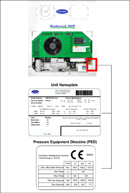
The unit nameplate provides the unit model number, parts identification number (PID) and serial number. The Pressure Equipment Directive (PED) compliance label is located near the nameplate.
1.Remove the back access panel on the back of the unit to gain access to the evaporator components.
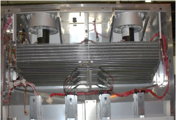
2.Evaporator Coil. Refer to Figure 1.
a.Clean with low pressure water. If the evaporator coil is noted to have green patina or white powder, it is recommended to wash the coil with cleaner P/N NU4371-88.
Refer to the TechLINE December 2010 issue for Evaporator Section Cleaning.
b.Straighten any fin damage using the correct fin comb (8 fins per inch).
c.Check for any signs of leaks or corrosion and repair / replace as necessary.
For certain cargos exposed to fumigation, it is recommended after the trip to carefully wash all internal parts in the evaporator section to avoid potential corrosion.
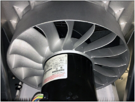
3.Evaporator Motor and Stator. Refer to Figure 2.
a.Slowly spin the evaporator fan blade and feel for any significant bearing drag. Replace the bearing if it is bad.
b.Check that the evaporator motor clamp brackets are secured. If not accessible, refer to step 17.
c.Check for excessive corrosion on the stator. If cleaning is needed, refer to step 2a.
4.Evaporator Fan Blade. Refer to Figure 2.
a.Check for cracking or wear. Replace the fan blade as necessary.
Figure 2 Evaporator Motor and Fan Blade
a.Examine for any worn or damaged wires and repair as required.
b.Ensure wire harnesses are properly secured.
6. Defrost Termination Sensor (DTS). Refer to Figure 3.
a.Ensure the DTS is properly secured to the unit and free of damage. Replace or repair if necessary.
Figure 3 Defrost Termination Sensor (DTS)
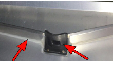
a.Inspect the drain cup and drain gutters. Refer to Figure 4. Repair as required.
Figure 4 Defrost Drain Cup and Gutters
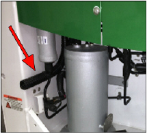
b.Clean the defrost drain lines using a low pressure water hose to flush debris contained in the drain. Check that the water is running freely from the outside drain. Refer to Figure 5.
8.Electronic Expansion Valve (EEV). Refer to Figure 6.
a.Check for refrigerant leaks and corrosion.
b.Verify that the EEV coil is connected to the stepper drive powerpack.
Figure 6 Electronic Expansion Valve (EEV)
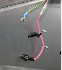
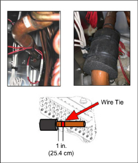
9.Evaporator Temperature Sensor (ETS). Refer to Figure 7.
a.Ensure that the wire tie is in position and insulation is in place.
Figure 7 Evaporator Temperature Sensor (ETS)
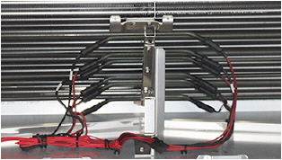
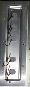
10.Heaters and Heater Brackets. Refer to Figure 8.
a.Check for damage.
b.Ensure that the heaters are properly positioned in the retaining clips.
c.Inspect wiring for correct connections, and repair if required.
Refer to the TechLINE June 2014 issue for heater Megaohm testing.
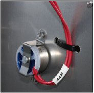
11.Heater Termination Thermostat (HTT). Refer to Figure 9.
a.Check for proper positioning and damage.
b.Replace as necessary.
Figure 9 Heater Termination Thermostat (HTT)
12.USDA and Interior Communication Sockets. Refer to Figure 10.
a.Check that connectors are clean, dry and have the caps fitted.
b.If corroded or cap is missing, repair or replace as needed.
a.Check channels or "T" bars on the floor and under the lower air baffle / kick plate for cleanliness.
b.Channels must be free of debris for proper air circulation.
d.Ensure that the kick plate is correctly installed and in good condition for correct air flow.
Units with PID lower than NT5010
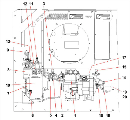
1)Compressor
2)Compressor Discharge Temperature Sensor (CPDS)
3)High Pressure Relief Valve (HPRV)
5)Gas Cooler Temperature Sensor (GCTS)
6)High Side Service Connection
7)Discharge Pressure Transducer (DPT)
9)High Pressure Expansion Valve (HPXV)
11)Flash Tank Pressure Relief Valve (FT PRV)
12)Flash Tank Pressure Transducer (FPT)
13)Economizer Solenoid Valve (ESV)
14)Unloader Solenoid Valve (USV)
15)Low Pressure Relief Valve (LPRV)
16)Low Side Service Connection
17)Suction Pressure Transducer (SPT)
18)Ambient Temperature Sensor (AMBS)
19)Supply Recorder Sensor (SRS)
20)Supply Temperature Sensor (STS)
Units with PID NT5010 and higher
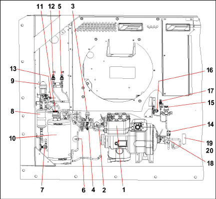
1)Compressor
2)Compressor Discharge Temperature Sensor (CPDS)
3)High Pressure Relief Valve (HPRV)
4)High Pressure Switch (HPS)
5)Discharge Pressure Transducer (DPT)
6)Gas Cooler Temperature Sensor (GCTS)
7)High Side Service Connection
8)Filter Drier
9)High Pressure Expansion Valve (HPXV)
10)Flash Tank
11)Flash Tank Pressure Relief Valve (FTPRV)
12)Flash Tank Pressure Transducer (FPT)
13)Economizer Solenoid Valve (ESV)
14)Unloader Solenoid Valve (USV)
15)Low Pressure Relief Valve (LPRV)
16)Low Side Service Connection
17)Suction Pressure Transducer (SPT)
18)Ambient Temperature Sensor (AMBS)
19)Supply Recorder Sensor (SRS)
20)Supply Temperature Sensor (STS)
Refer to the Warnings and Notes section in this manual before proceeding with these instructions.
14.Remove or Open Exterior Panels.
a.Examine the unit for traces of oil residue. Leak check the unit using an electronic leak detector. Leaks are typically found as a dirty / oily residue near the leak location. All mechanical joints to be leak tested can be found in the Appendix. Repair as required and clean the unit using low pressure water.
Perform on-going corrosion maintenance if corrosion found on any painted surface. Perform these steps:
a.Remove loose corrosion material.
b.Lightly scuff up the surface with a Scotch-Brite heavy duty scour pad (or similar).
c.Wipe down with isopropyl alcohol to remove loose material and any grease.
d.Paint using the following standard paint specifications (purchase locally).
Part |
Color |
Brand |
Paint |
|---|---|---|---|
Compressor / Flash Tank |
Grey |
DNT |
V-TOP #188 |
Frame |
White Cloud |
Rust-Oleum |
9100 System |
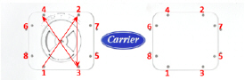
17.Access Panels. Refer to Figure 11.
a.Remove the left and right hand evaporator access panels.
b.Check that the access panel seals are present and in good condition to provide a good seal.
c.Check for excessive shaft end play on the evaporator motor.
d.Replace panels on completion assuring all hardware (including the Mylar washer) is installed.
e.When reinstalling the panels, use a torque setting of 60 +5 in-lbs. (6.8 N-M) and the pattern shown in Figure 11.
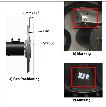
18.Gas Cooler Motor and Fan Blade. Refer to Figure 12.
a.Check for cracking or wear on the fan blade. Replace as necessary.
b.Check for proper fan positioning in the shroud. See Figure 12 (a) for reference.
c.Slowly spin the fan blade, feeling for any bearing drag. Replace the motor if the fan is unable to freely rotate.
d.Examine the fan motor for signs of overheating or physical damage. Repair or replace as necessary.
e.Check the motor mounting bracket for cracking where welded to the frame. See Figure 12 (b). Repair if necessary.
f.Verify the fan has HFF marked on the hub which is raised and painted. See Figure 12 (c).
Figure 12 Gas Cooler Fan Position and Markings
a.Check for any signs of leaks. Repair or replace as necessary.
b.Straighten any fin damage using fin comb (16 FPI).
c.Clean the coil using a low pressure water hose. The preferred wash direction is inside to outside. Refer to Figure 13. The direction is opposite to air flow direction.
Static application of container units may require more frequent cleaning due to subjected environment conditions.
d.Check for signs of excessive corrosion to the fins and tube sheets. Replace as necessary.
Figure 13 Gas Cooler Coil Cleaning
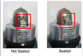
20.High Pressure Expansion Valve (HPXV). Refer to Figure 14.
a.Make sure the HPXV coil is snapped down fully and the coil retention tab is properly seated in one of the valve body dimples.
b.Ensure that the coil boot is properly fitted over the valve body.
Figure 14 High Pressure Expansion Valve (HPXV) and Coil
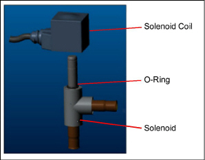
21.Economizer and Unloader Valve (ESV / USV). Refer to Figure 15.
b.Verify that the O-ring is seated on the valve stem.
c.Press the coil onto the valve stem ensuring that it is pressed all the way down, engaging with the O-ring.
Figure 15 Economizer and Unloader Valve (ESV / USV)
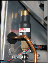
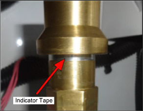
22.Pressure Relief Valves (LS, FT & HS). Refer to Figure 16.
a.Inspect the pressure relief valves for any indication of release on the indicator tape. If there is indication of a release, replace the pressure relief valves.
Figure 16 Pressure Relief Valves (LS, FT & HS)
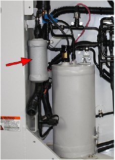
23.Filter Drier. Refer to Figure 17.
a.Check for excessive corrosion or physical damage of the filter drier and replace as required.
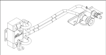
24.Water-Cooled Condenser (Optional). Refer to Figure 18.
a.Inspect assembly for excessive corrosion or physical damage. Repair or replace as necessary.
b.Check the water connections for damage and the collar on the female fitting to ensure it moves freely.
Figure 18 Water-Cooled Condenser
a.Check that the cable is securely attached to the unit and the clamp is in position. See Figure 19.
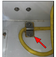
b.Inspect the cable for any physical damage.
c.Replace the cable if more than one repair splice is found.
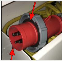
d.Examine the plug gasket for any cracking / damage and replace if necessary. See Figure 20.
e.Inspect the male pins. Replace if evidence of arcing / pitting or if the locating lug is missing. See Figure 20.
Figure 20 Gasket / Locating Lug
f.Disassemble the plug from the cable and tighten wires to the pins. Reassemble the plug making sure the cable gland is tight and sealing the cable.
g.Carry out a Megohm test from the power plug ground pin to the ground plate in the control box. The Megohm reading of this test should be zero.
h.Carry out a Megohm test from each power plug pin to ground. The Megohm reading for the power plug ground pin should be zero and infinity for the other power plug pins.
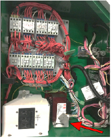
a.Interior should be dry and free from signs of damage, overheating, and corrosion. Repair any damage to the control box door gasket if needed.
b.Secure all loose wires with wire ties.
c.Examine contacts for severe pitting, and replace the contactor if necessary.
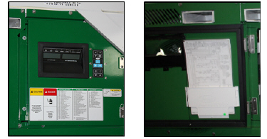
d.Check to make sure wiring diagrams and schematics are present and legible. Replace if missing or damaged.
e.Inspect for damage and check tightness on all wire harnesses and connections using a Pozi drive (star) screwdriver.
f.All instructional labels and placards should be in place and legible. Refer to Figure 21.
Figure 21 Instructional Labels and Placards
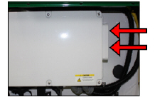
27.Interrogation Sockets. Refer to Figure 22.
a.Ensure ports are secure and free from damage and corrosion.
b.Make sure the caps are properly tethered to the unit.
c.Repair or replace if damaged or missing.
Figure 22 Interrogation Sockets
a.Examine loose wires and wire harnesses outside of the control box for routing neatness and condition. Replace or repair as necessary.
a.Inspect structural integrity of the unit. Check unit for cracks, damage and missing structural items. Repair as required. If painting is required, refer to step 16.
Refer to Warnings and Notes on page 2 before proceeding.
30.Remove the Lock Out / Tag Out device and plug the unit in to power supply.
31.Install the manifold gauge set.
32.Turn unit power on and change the setpoint to 32°F (0°C).
33.Check that voltage is good on all 3 phases of CH Contactor.
b.Acceptable ranges are: 50Hz, 360-460V & 60Hz, 400-500V.
34.Verify the container software / model / ID / time.
a.Check Cd18 to verify the software installed (57xx). It is recommend to always have the latest software installed.
b.Check Cd20 to verify the model number. This should match the last 5 digits of the model number on the nameplate (i.e. for 69NT40-601-101 the display will show 01101).
c.Check Cd40 to verify the Container ID to ensure correct set up.
d.Check dC32, dC33, dC34 to verify the clock is set to the current Greenwich Mean Time (GMT).
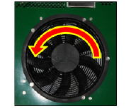
35.Check fans for proper rotation.
a.Check the gas cooler fan by placing a piece of paper on the gas cooler grill and verify it is blowing out. Refer to Figure 23.
Figure 23 Gas Cooler Fan Rotation
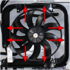
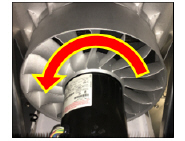
b.Check the evaporator fans by verifying that air is pushing out by the bottom kick plate and sucking in on the top grille. Refer to Figure 24.
Figure 24 Evaporator Fan Rotation
c.Check the VFD fan by placing a piece of paper over the fan grille to verify it pulls in. Refer to Figure 25.
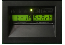
36.Enter a DataCORDER Trip Start. Refer to Figure 26.
a.By entering a trip start first, all test data will be included as part of the maintenance record.
b.Press the ALT MODE key. When the left display shows "dC", press the ENTER key.
c.Use the Arrow keys to scroll to Code dC30.
d.Press and hold the ENTER key for five seconds.
e.The "Trip Start" event will be entered in the DataCORDER.
37.Check the discharge and suction pressures on the manifold gauge set. Refer to the Operations and Service Manual for R744 Pressure-Temperature Chart.
38.Ensure that User Selectable ML3 codes Cd 27-37 are set to the customer specific default values to be advised by the customer. Factory default settings are below.
Code |
Title |
Default |
Options |
|---|---|---|---|
Cd27 |
Defrost Interval |
Auto |
Auto, Off, 3, 6, 9, 12, 24 |
Cd28 |
Standard Temperature Units |
Celsius |
F, C, --- (lockout option) |
Cd29 |
User Selectable Failure Response Code |
d = Full System Shutdown |
A = Evap Fan Only d = Full System Shutdown |
Cd30 |
In-Range Tolerance |
4 = ± 2.0°C (± 3.6°F) |
1 = ±0.5°C (±0.9°F) 2 = ±1.0°C (± 1.8°F) 3 = ±1.5°C (± 2.7°F) 4 = ±2.0°C (± 3.6°F) |
Cd32 |
System Current Limit |
21 Amps |
15, 17, 19, 21, 23 |
Cd33 |
Humidity Setpoint |
Option - Refer to CnF04 |
- |
Cd35 |
Bulb Mode |
Option - Refer to CnF28 |
----, nOr, bULb |
Cd36 |
Evaporator Fan Speed |
Bulb Mode |
----, Alt, LOW, HI |
Cd37 |
Variable DTT Setting |
Bulb Mode |
----, nOr |
40.During pull-down, check the unit for unusual noise / vibrations (i.e. loose connections). If found, investigate and repair.
41.Allow the unit to complete testing. Refer to the operation & service manual for any failed PTI test and repair.
42.Perform an Upper Vent Position Sensor (VPS) calibration (optional equipment).
a.Rotate the vent to the 0 CMH / CFM position. Cd45 will automatically display.
b.Press the ENTER key and hold for five seconds. After the ENTER key has been pressed, the display reads “CAL” (for calibration).
43.Press the ALT MODE key and hold for five seconds. After the calibration has been completed, Cd45 will display 0 CMH / CFM.
44.Download (interrogate) the unit DataCORDER using a PCMCIA downloading card, USB adapter or DataLINE. It is recommended to get an "ALL DATA" download for records. The minimum should be "LAST TRIP START" to ensure all PM temperature and PTI data is obtained.
45.Turn the unit off and disconnect from the power supply.
46.Print out the trip report and retain it as a permanent record of the PM.
47.Retain the download and inspection sheet as a record of the annual inspection.
Pressure Relief Valves |
PIDs lower than NT5010 |
|
Low Side PRV |
88.1-96.3 Nm (65-71 ft-lb) |
|
Flash Tank PRV |
29.8-32.5 Nm (22-24 ft-lb) |
|
High Side PRV |
51.5-56.9 Nm (38-42 ft-lb) |
|
PIDs NT5010 and higher |
||
Low Side PRV |
77.3-85.4 Nm (57-63 ft-lb) |
|
Flash Tank PRV |
29.8-32.5 Nm (22-24 ft-lb) |
|
High Side PRV |
51.5-56.9 Nm (38-42 ft-lb) |
|
Pressure Transducers |
PIDs lower than NT5010 |
|
Suction Pressure Transducer (SPT) |
25.7-28.5 Nm (19-21 ft-lb) |
|
Flash Tank Pressure Transducer (FTPT) |
9.5-12.2 Nm (7-8 ft-lb) |
|
Discharge Pressure Transducer (DPT) |
9.5-12.2 Nm (7-8 ft-lb) |
|
Service Fittings / Service Valves |
PIDs lower than NT5010 |
|
Suction Service Fitting |
25.7-28.5 Nm (19-21 ft-lb) |
|
Discharge Service Fitting |
9.5-12.2 Nm (7-8 ft-lb) |
|
PIDs NT5010 and higher |
||
Suction or Discharge Service Valve |
|
|
Top Cap |
10-14 Nm (7-10 ft-lb) |
|
Stem, Open |
Max. 2 Nm (1.5 ft-lb) |
|
Stem, Closed |
6-8 Nm (4-6 ft-lb) |
|
Flare Cap |
10-14 Nm (7-10 ft-lb) |
|
Filter Drier |
Filter Drier |
18.4-22.1 Nm (25-30 ft-lb) |
Pressure Switch |
High Pressure Switch |
17.6-19 Nm (13-14 ft-lb) |
Bolts |
Compressor Flange Bolts |
35.3-38 Nm (26-28 ft-lb)
|
Table 1–2 Mechanical Joints for Leak Inspection
Component |
Location |
|---|---|
Compressor |
1st Stage Suction Flange |
1st Stage Discharge Flange |
|
2nd Stage Suction Flange |
|
2nd Stage Discharge Flange |
|
Pressure Relief Valves |
Low Side PRV |
Flash Tank PRV |
|
High Side PRV |
|
Pressure Transducers |
Compressor |
Flash Tank |
|
Discharge |
|
Charging Port |
Low Side |
High Side |
|
High Pressure Switch |
Plug
located on Flash Tank Liquid Line |
Filter Drier |
Inlet |
Outlet |
°C |
°F |
OHMS |
|
°C |
°F |
OHMS |
|---|---|---|---|---|---|---|
-40 |
-40 |
849,822 |
|
18 |
64.4 |
136,705 |
-38 |
-36.4 |
834,450 |
|
20 |
68.0 |
124,876 |
-36 |
-32.8 |
819,079 |
|
22 |
71.6 |
114,101 |
-34 |
-29.2 |
803,707 |
|
24 |
75.2 |
104,352 |
-32 |
-25.6 |
788,336 |
|
25 |
77 |
100,000 |
-30 |
-22.0 |
772,964 |
|
26 |
78.8 |
95,585 |
-28 |
-18.4 |
757,593 |
|
28 |
82.4 |
87,619 |
-26 |
-14.8 |
742,221 |
|
30 |
83.0 |
80,447 |
-24 |
-11.2 |
726,849 |
|
32 |
89.6 |
73,931 |
-22 |
-7.6 |
711,478 |
|
34 |
93.2 |
68,000 |
-20 |
-4.0 |
696,106 |
|
36 |
96.8 |
62,599 |
-18 |
-0.4 |
680,735 |
|
38 |
100.4 |
57,657 |
-16 |
3.2 |
665,363 |
|
40 |
104.0 |
53,200 |
-14 |
6.8 |
649,992 |
|
42 |
107.6 |
49,117 |
-12 |
10.4 |
620,224 |
|
44 |
111.2 |
45,367 |
-10 |
14.0 |
563,722 |
|
46 |
114.8 |
41,965 |
-8 |
17.6 |
507,219 |
|
48 |
118.4 |
38,840 |
-6 |
21.2 |
450,717 |
|
50 |
122.0 |
35,991 |
-4 |
24.8 |
403,140 |
|
52 |
125.6 |
33,369 |
-2 |
28.4 |
365,427 |
|
54 |
129.2 |
30,967 |
0 |
32.0 |
327,715 |
|
56 |
132.8 |
28,753 |
2 |
35.6 |
295,834 |
|
58 |
136.4 |
26,733 |
4 |
39.2 |
267,922 |
|
60 |
140.0 |
24,867 |
6 |
42.8 |
241,618 |
|
62 |
143.6 |
23,152 |
8 |
46.4 |
219,659 |
|
64 |
147.2 |
21,570 |
10 |
50.0 |
198,927 |
|
66 |
150.8 |
20,827 |
12 |
53.6 |
180,987 |
|
68 |
154.4 |
20,112 |
14 |
57.2 |
164,687 |
|
70 |
158.0 |
18,768 |
16 |
60.8 |
149,680 |
|
72 |
161.6 |
16,375 |
Manual Reference: T-349 & T-370
Unit Detail |
Customer |
|
Unit Serial # |
|
|
Container # |
|
|
Port / Location of Inspection |
|
|
Person Inspecting Unit |
|
|
Date & Time of Inspection |
|
|
Compressor Run Time (hrs) |
|
|
Software Revision |
|
Test |
|
|
Comments |
Perform Auto 2 PTI |
Collect and provide download along with actions required for it to pass |
|
|
Active Alarms (If Any) |
|
Leak Inspect: (Use Tool Part Number 07-00529-00) |
Component |
Location |
Leak? Comments |
Compressor |
1st Stage Suction |
|
|
1st Stage Discharge |
|
||
2nd Stage Suction |
|
||
2nd Stage Discharge |
|
||
Pressure Relief Valves |
Compressor (LS) |
|
|
Flash Tank (MS) |
|
||
Discharge (HS) |
|
||
Pressure Transducer |
Compressor |
|
|
Flash Tank |
|
||
Discharge |
|
||
Charging Port |
Low Side |
|
|
High Side |
|
||
High Pressure Switch |
|
||
Sight Glass Plug (If Equipped) |
|
||
Filter Drier |
Inlet |
|
|
Outlet |
|
||
Photos |
Location |
Comments |
Front of Unit |
|
|
Compressor |
|
|
Flash Tank |
|
|
Gas Cooler |
|
|
Oil Residue (If Any) |
|
|
Corrosion (If Any) |
|
General Comments |
|
|