This manual has been written to assist owners and operators of Carrier Transicold MicroLink equipment in obtaining the maximum operating life from the equipment. It is written as an annual maintenance guide for ThinLINE and PrimeLINE units and it is recommended that all units are serviced with these procedures annually to obtain maximum operating time from the equipment.
This manual is to be used in conjunction with the operations & service manuals supplied with the equipment. Reference is made throughout these pages to the operations & service manuals, which are posted electronically on the Carrier Transicold Container website
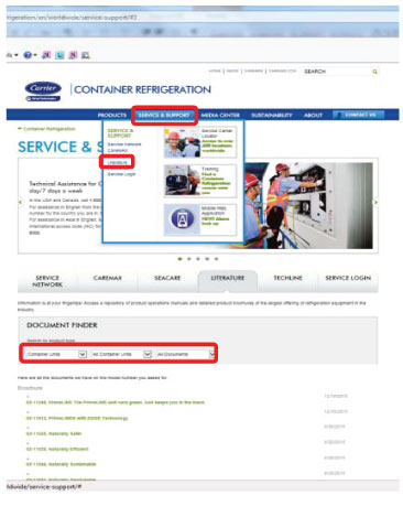
http://www.carrier.com/container-refrigeration/
Navigate to SERVICE & SUPPORT / LITERATURE / DOCUMENT FINDER (Refer to Figure 1).
Figure 1 Carrier Transicold Container Website
•Wrench set, 3/8 to 11/16
•Screwdrivers, flat, crosspoint (Phillips) and Pozi-Drive
•Torque wrench and sockets
•R134a Refrigerant leak detector
•Refrigeration gauge set
•Fin comb
•Megohm meter
•Multimeter, with voltage and resistance ranges
|
1.Before opening any panels for inspection or replacing any electrical component in the system, apply the Lock Out/Tag Out procedure, turn the unit off, open the unit circuit breakers (CB1 and CB2 if equipped) and unplug the unit from main power. Apply a locking device to ensure the system cannot be plugged in during the maintenance procedure.
2.Carrier Transicold recommends wearing the appropriate safety equipment such as safety glasses, gloves, etc. whenever working on refrigeration equipment. Personnel should be aware of the dangers inherent in servicing equipment and assure they have read the relevant operations and service manual for any unit.
3.To prevent damage to aluminum we recommend low pressure fresh water cleaning. See evaporator coil section for exception.
4.All local requirements for recovery and safe disposal of refrigerants and oils must be followed.
The Model/Serial Number plate provides the unit model number (Refer to Figure 2).
Figure 2 Model/Serial Number plate


Rear of Unit
1.Remove the upper internal access panel, remove any debris, and rinse the rear of unit with low pressure water. This includes the evaporator coil (Refer to Figure 3).
2.Examine the evaporator motors for excessive end play. Slowly spin the evaporator fan blade and feel for any bearing drag. Replace bearing if required.
3.Examine the evaporator fan blade (Refer to Figure 4):
a.Check for cracking or wear. Replace fan blade as necessary.
b.Check that evaporator motor clamp brackets are secured.
4.Examine wire harnesses for any wear or damage and repair as required. Ensure they are properly secured.
5.Examine defrost termination sensor (DTS) to ensure it is properly secured to the unit and free of damage (Refer to Figure 5). Replace or repair if necessary.

6.Examine sensors (i.e. return air, supply air, temperature recorder, humidity and evaporator temperature sensors) for proper positioning and security to unit. Examine sensor leads for damage, replace or repair as necessary. Refer to the operation & service manual for details on equipped sensors. Locating operation & service manuals is explained in the Purpose section.
7.Examine the drain cup, drain funnel and drain gutters. Repair as required.
8.Clean the defrost drain lines using a low pressure water hose to flush debris contained in the drain (Refer to Figure 6), and check that the water is running freely to the outside.

9.Examine the TXV (Thermostatic Expansion Valve) or EEV (Electronic Expansion Valve) for:
a.Refrigerant leaks (TXV or EEV).
b.Corrosion (TXV or EEV).
c.Proper insulation of the power head (TXV equipped, refer to Figure 7).
d.Proper sensing bulb location and insulation (TXV equipped, refer to Figure 7).
e.Electrical coil is correctly seated on the EEV (EEV equipped, refer to Figure 8).
f.EEV coil boot is properly fitted over valve (EEV equipped, refer to Figure 8).
g.Correct position of ETS1 and ETS2, securing tie is in position and insulation is in place (Refer to Figure 9).
|
|
|

10.Examine the Evaporator coil:
a.Clean with low pressure water. If the evaporator coil is noted to have green patina or white powder, it is recommended to wash the coil with cleaner P/N NU4371-88. Refer to TechLINE December 2010 issue for Evaporator Section Cleaning.
b.Straighten any fin damage using the correct fin comb.
c.Check for any signs of leaks, and repair or replace as necessary.
d.Check for any signs of corrosion, and repair or replace as necessary.
For certain cargos exposed to fumigation, it is recommended after the trip to carefully wash all internal parts in the evaporator section to avoid potential corrosion.
11.Examine the heaters and heater brackets for damage (Refer to Figure 10). Ensure the heaters are properly positioned in the retaining clips. Inspect wiring for correct connections, and repair if required. Refer to TechLINE June 2014 issue for heater troubleshooting.

12.Examine the heater termination thermostat (HTT) for proper positioning/damage (Refer to Figure 11). Replace as necessary.
Figure 11 Heater Termination Thermostat

13.Examine internal valves, solenoid coils, as required per unit model number checking for proper positioning, physical damage, leaks or corrosion. Clean, repair or replace as necessary. Refer to the operation & service manual for details on equipped valves. Locating operation & service manuals is explained in the Purpose section.
14.Check channels or “T” bars on the floor and under the lower air baffle, and kick plate, for cleanliness. Channels must be free of debris for proper air circulation. Clean floor drains. Ensure that the kick plate is correctly installed and in good condition for correct air flow.
15.Check container panels, insulation, and door seals for damage. Repair as required.
16.Check that USDA and interior communication sockets are clean, dry and have the caps fitted.
17.Refit the upper access panel, and ensure all hardware is correctly fitted. Replace as required.
Front of Unit
Refer to the Warnings and Notes section in this manual before proceeding with these instructions.
Remove All Exterior Panels
1.Examine unit for traces of oil residue. Leak check the unit, including the compressor, using an electronic leak detector. Leaks are typically found as a dirty/oily residue on compressor joints, high pressure switch connection, pressure transducers (if fitted), piping connections etc. Repair as required and clean the unit using low pressure water, including the condenser coil.
2.Rust prevention and maintenance of painted surfaces (Refer to Figure 12).
On-going corrosion maintenance is required. If corrosion is found on any painted surface, remove corrosion, prime, and paint using the following standard paint specifications.
Paint |
Part Number |
White |
P/N 36-00071-16 |
Blue |
P/N 76-00397-01 |

3.Ensure that the remote monitoring and interrogation sockets are secure and free from damage and corrosion and caps are properly tethered to the unit (Refer to Figure 13). Repair/replace as required.
Figure 13 Interrogation Socket

4.Inspect the compressor and mounting plate for severe corrosion, and check compressor shock mount for damage (cracks). Repair or replace as necessary. Torque the mounting bolts according to specifications in the operation & service manual. Locating operation & service manuals is explained in the Purpose section.
5.Inspect the electrical control box (Refer to Figure 14):
a.Interior should be dry and free from signs of damage, overheating, corrosion, and moisture ingress. Repair any damage to the control box door gasket.
b.Wire tie all loose wires.
c.Examine contacts for severe pitting, and replace contactor if necessary.
d.Check to make sure wiring diagrams and schematics are present and legible. Replace if missing or damaged.
e.Inspect the circuit breaker panel for damage and corrosion.
f.Inspect for damage and check tightness on all wire harnesses and connections in control box, repair or replace as necessary. Use of a Pozi drive (star) screwdriver is critical to assuring the tightness of contactor wire screws.
g.Carry out a Megohm test on all motors and heaters. Replace components if test is below the TechLINE minimum recommendation or as specified by customer if higher. Refer to TechLINE June 2014 issue for Megohm Readings.
Figure 14 Electrical Control Box

6.Examine condenser motor and fan blade:
a.Check for cracking or wear on the fan blade. Replace as necessary.
b.Check for proper fan positioning in the venturi, refer to the operation & service manual for proper positioning instructions. Locating operation & service manuals is explained in the Purpose section.
c.Slowly spin the condenser fan blade, feeling for any bearing drag. Replace bearings as necessary.
d.Examine fan motor for corrosion, signs of overheating, or physical damage. Repair or replace as necessary.
e.Check the CF mounting bracket for cracking where welded to the bulkhead.
7.Examine condenser coil:
a.Check for any signs of leaks. Repair or replace as necessary.
b.Straighten any fin damage.
c.Clean the coil using a low pressure water hose. For a flat coil (Refer to Figure 15) the preferred wash direction is top down, for a C coil (Refer to Figure 16) inside to outside. In both cases, direction is opposite to air flow direction.
d.Check for signs of excessive corrosion to the fins and tube sheets. Replace as necessary.


8.Examine the flexible condensate defrost drain tube (Refer to Figure 17). The tube should be undamaged and free from blockage or debris. It may be necessary to remove the condenser fan for complete access.
Figure 17 Condensate Defrost Drain Tube

9.Examine external valves, coils, sight glasses, pressure transducers as equipped per the unit model number checking for physical damage, leaks or corrosion. Clean, repair or replace as necessary. Refer to the operation & service manual for details on equipped valves. Locating operation & service manuals is explained in the Purpose section.
10.Inspect filter/drier for excessive corrosion or physical damage, and replace as required (Refer to Figure 18). Periodic paint touch up of the filter may be required.

11.Examine the water-cooled condenser (if equipped, refer to Figure 19):
a.Periodic paint touch up of the water-cooled condenser may be required.
b.Determine whether the water-cooled condenser is scaled. Refer to the operation & service manual for specific details on cleaning and maintenance of the water-cooled condenser. Locating operation & service manuals is explained in the Purpose section.
c.Inspect assembly for excessive corrosion or physical damage. Repair or replace as necessary.
d.Check the water connections for damage and the collar on the female fitting to ensure it moves freely.
Figure 19 Water-Cooled Condenser

12.Examine power cables:
a.Check the cable to make sure it is securely attached to the unit and the clamp is in position.
b.Replace or repair the cable if damaged or crushed in any manner. Replace the cable if more than one repair joint is found.
c.Replace the plug if pins are burned or pitted, or if locating lug is missing (Refer to Figure 20).
d.Disassemble the plug from cable and tighten wires to the pins, reassemble the plug making sure the cable gland is tight and sealing cable.
e.Examine the plug gasket for any cracking/damage and replace if necessary.
f.Carry out a Megohm test from power plug ground pin to the ground plate in the control box. The Megohm reading of this test should be zero.
g.Carry out a Megohm test from each power plug pin to ground. The Megohm reading for the power plug ground pin should be zero, and infinity for the other power plug pins.

13.Refit all exterior panels, examine all door seals, check for proper alignment and water tight integrity. All door fasteners and fastening bolts (including Mylar washers where required) should be present and should tightly secure the doors. Replace any gaskets that are brittle or cracked for the following:
a.Control box
b.Access panels
c.Fresh air make-up slide
14.Remove left and right hand evaporator access panels. Ensure the evaporator motor mounting brackets or the evaporator motor stator brackets are properly torqued. Refer to the operation & service manual for specific torque values. Locating operation & service manuals is explained in the Purpose section. Replace panels on completion assuring all hardware, inclusive of the Mylar washer are installed. Check that the access panel seals are present and in good condition and that they seal well when panels are refitted. Use torque setting: 60 +5 in-lbs.
15.Examine wires and wire harnesses not contained in the control box for proper location and condition. Replace or repair as necessary.
For Example:
a.Wires to valves
b.Wires to heaters
c.Switch wires
d.Compressor terminal wires
16.All instructional labels and placards should be in place and legible (Refer to Figure 21). The Model/Serial Number plate should also be in place (Refer to Figure 17).
Figure 21 Instruction Labels and Placards

17.Inspect structural integrity of the unit. Check unit for cracks, damage and missing structural items. Repair as required.
Refer to Warnings and Notes on page 2 before proceeding.
1.Remove the Lock Out/Tag Out device and plug unit in to power supply. Check that voltage is good on all 3 phases.
2.Install the manifold gauge set using good system hygiene practices. For PrimeLINE units, operating pressures can be viewed by going to code 12 (Suction Pressure) and code 14 (Discharge Pressure).
3.Turn unit power on and change the set point to 32ºF (0ºC). Check Container ID on start up to ensure correct set up and also verify the date and time is set to GMT. Check that the correct software and configuration are loaded in the MicroLink controller on start up or check at codes 18 and 20. Note: It is recommended to have always the latest operational software loaded in the controller.
4.Check the condenser and both evaporator fans for proper rotation (Refer to Figure 22).
Figure 22 Evaporator and Condenser Fans Proper Rotation

5.Enter a DataCORDER Trip Start (Refer to Figure 23). Consult the instruction label on the face of the unit for correct procedure.
Figure 23 DataCORDER Trip start

6.Check the discharge and suction pressures on manifold gauge set (or through codes), consult the operation & service manual for acceptable pressure levels based on ambient temperature. Locating operation & service manuals is explained in the Purpose section.
7.Ensure that User Selectable Micro link codes, codes 26 and higher, are set to customer defaults values.
8.Initiate Auto 2 PTI.
During pull-down:
a.Check the unit for unusual noise/vibrations.
b.During PTI test 8 check refrigerant level in the unit (Refer to Figure 25).
9.Allow the unit to complete testing. Repair any faults associated with failing PTI tests (Refer to Figure 24). Refer to the operation & service manual for details on troubleshooting procedures. Locating operation & service manuals is explained in the Purpose section.
On completion proceed to step 10.

10.Check the unit’s TXV and EEV superheat setting. Consult the operation & service manual for the correct superheat setting and procedure. Valve settings should not be adjusted if incorrect superheat is observed then the valve or sensors must be replaced. Note: For PrimeLINE units, the superheat can be observed at code 54.
11.Check filter drier operation by monitoring the temperature difference across the drier. Excessive temperature drop across the drier or frosting indicates a restriction in the filter and the filter should be replaced.
12.Check for proper color of moisture/liquid indicator (Refer to Figure 25). If moisture is indicated:
a.Evacuate and dehydrate the system.
b.Replace the unit filter drier.
c.Use Total Test kit to determine if acid or moisture remains in the system.

13.Inspect water fittings on the water-cooled condenser (if equipped) for damage. Pressurize connections and record value of water pressure switch cut-out and cut-in. Check the operation & service manual for the correct switch cut-in and cut-out pressures. Locating operation & service manuals is explained in the Purpose section.
14.Download (interrogate) the unit DataCORDER, Example: Using DataBANK downloading card (Refer to Figure 26). The download should be performed from the “Last Trip Start” to ensure all PM temperature and PTI data are obtained. Consult the interrogation manual for proper downloading procedures.
Figure 26 DataBANK Downloading Card

15.Turn the unit off and disconnect from power supply.
16.Print out the trip report and retain it as a permanent record of the PM.


