
Section 10
Probe and Sensor Calibration Screen
This section describes the features available on the Calibration screens when using the Probe Calibration utility. Through the use of these screens, DataLINE provides an interface to perform temperature sensor calibration.
There are two versions of the probe calibration utility:
1.Units with ML3 controllers loaded with SWR53xx series controller software SWR5368 or greater:
•Calibration of USDA sensors, supply and return sensors, control and recording sensors.
2.Units with ML3 controllers loaded with SWR51xx series, SWR53xx below 5368, SWR57xx series and all ML2i controllers:
•Calibration of USDA sensors.
The screens and procedures change depending on the controller version installed.
10.2Units with ML3 controllers loaded with SWR53xx series controller software from SWR5368
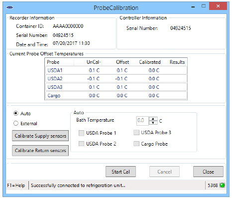
The Probe Calibration screen (Figure 10.1) will be displayed when the user clicks on the Probe Calibration button on the DataLINE Launch Pad or the Auto option button. From this screen the user can perform USDA/Cargo probe calibration using either the Auto or external methodology. In addition, there is the option to calibrate Supply Air and Return Air Temperature sensors.
When DataLINE has established a connection with a container unit, each calibration screen displays the following information:
•DataCorder (Recorder) information
•Controller information
•Temperature probe/sensor information
•Controls related to the selected calibration option
•Controller software version
The connection status with the container unit is also reported at the bottom of the screen. If DataLINE is not able to communicate with the refrigeration unit, X's will be presented in the data fields.
DataLINE refreshes the calibration screens in two ways:
•AutoRefresh - Every 15 seconds the probe calibration screen automatically updates all data in the “Recorder Information”, and “Controller Information” Group Boxes. It will also update sensor information in the “Current Probe Offset Temperatures” group box. However, the information in the Results column will only be updated when calibration is in progress and when complete.
•F9 - Provides a shortcut for manually triggering the refresh operation.
The following procedure is used to perform USDA and Cargo Probe calibration. The user can choose to use either of the two options that are available:
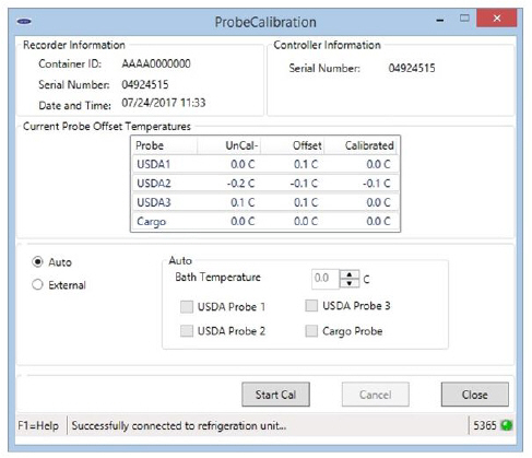
•Auto - The MicroLink controller in the container unit calculates the offsets for all probes using an assumed ice-bath temperature of 0.0°C (32°F). The user cannot select probes or change the ice bath temperature value. Once initiated, calibration is performed when the probes are determined to be stable by the controller.
•External - The user explicitly specifies the offset to be used for each probe that is to be calibrated. Offset values between -0.3°C and +0.3°C (-0.5°F and +0.5°F) can be entered.
By default, the Auto Calibration screen (Figure 10.2) is displayed. It can also be displayed by choosing the Auto option button if it is not selected. Prior to displaying this screen, the user is reminded to verify the ice bath to be used is at 0°C (32°F).
Procedure:
1.Prepare proper ice bath and ensure that it has stabilized at 0°C (32°F). See Ice Bath Preparation Procedure and Equipment.
2.Place all USDA probes to be calibrated in the ice bath and observe readings on the screen.
3.Once probe readings have reached equilibrium and ice bath is 0°C (32°F), press the “Start Cal” button.
4.During the 5 minute period that calibration is attempted, confirm that the ice bath remains at 0°C (32°F). If the ice bath temperature changes, press “Cancel” to stop calibration.
5.Probes are calibrated individually once they are determined to be stable.
6.The calibration process is complete once all probes have been calibrated or the end of the 5 minute period is reached. Results are reported on the screen for each probe as follows:
•Passed - probe remained stable, offset within ±0.3°C (±0.5°F) has been calculated. (Offset saved)
•Failed - invalid probe, probe not stable, calculated offset outside of ±0.3°C (±0.5°F). Offset set to 0.0°C (0.0°F)
•No Cal - calibration was canceled before probe was calibrated. (Offset set to 0.0°C (0.0°F))
7.“Start Cal” (Figure 10.3) can be pressed to perform calibration again. If calibration is successful, press “Close” to exit Probe Calibration.
Figure 10.3 USDA/Cargo Probe Calibration (Auto) During Calibration
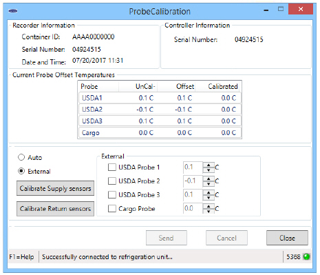
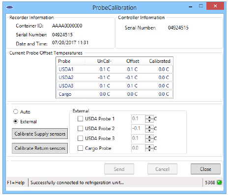
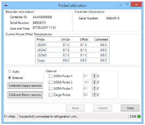
The Probe Calibration screen (Figure 10.4) is displayed when the user clicks on the External option button on the Probe Calibration screen.
Figure 10.4 Probe Calibration Screen
Procedure:
1.Check the box in front of the first probe needing calibration to activate the offset entry box.
2.Use the arrows or type an offset value into the entry box to use for the probe. (up to ±0.3°C (±0.5°F))
3.Repeat steps 1 and 2 for each probe being calibrated.
4.Press the “Send” button to calibrate the sensors using the offsets that were entered.
5.Press the “Close” button to exit Probe Calibration.
10.2.2Supply Air and Return Air Temperature Sensor Calibration (SWR 5368 and higher only)
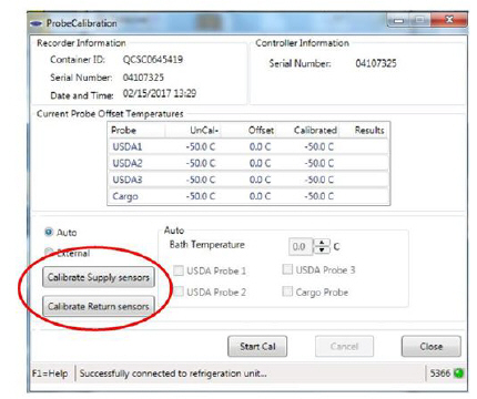
Supply Air and Return Air Temperature sensors can be calibrated similar to USDA and Cargo probes. The screens used to perform this operation are accessed by pressing the “Calibrate Supply Sensors” or “Calibrate Return Sensors” buttons on the USDA/Cargo probe screens.
These instructions should be read through completely before proceeding.
Before proceeding with dismantling of Supply and Return air sensors, set ON/OFF switch and circuit breaker to OFF position. Disconnect power plug from the unit. Follow proper lockout/tag out procedures to ensure the power cannot inadvertently be energized. It is important that all dismantling work is done and tools and personnel are away from the unit before powering on the unit for calibration.
When performing the return air sensor calibration, disconnect both evaporator motors.
Before proceeding with the calibration procedure, ensure that the controller software is 5368 or higher and DataLINE 3.1 or higher is installed onto the download device. Only the latest DataLINE and Controller software will allow users to carry out Good Distribution Practice (GDP) Calibration. Do not downgrade the software after installing the latest software. Read appendix A for the Ice bath preparation procedure before beginning the calibration process. It is also recommended this procedure be done before the full pre-trip inspection.
Before proceeding with the calibration procedure, it is recommended to check the sensors by running pretrip P5-0. This test checks the sensor values. If the test fails identify and correct the faulty sensor and rerun the test
Supply Air Sensors Calibration
1.Locate the sensor cover assembly on the suction side of the compressor. Remove the two fasteners securing the cover of the sensors, remove the cover and rotate supply air sensors (STS/SRS) in a clockwise direction. Remove the sensors from the sensor housing (Figure 10.5).
Figure 10.5 Supply Air Sensor Removal
2.Connect the interrogator cable to the interrogator port, then power on the unit.
Before powering on the unit, it is important to ensure that all dismantling work is done and tools are away and service personnel are not working on the unit at the time of power on.
3.On the Probe Calibration screen (Figure 10.6) select which pair of sensors you will be calibrating.
Figure 10.6 Sensor Selection from Probe Calibration Screen
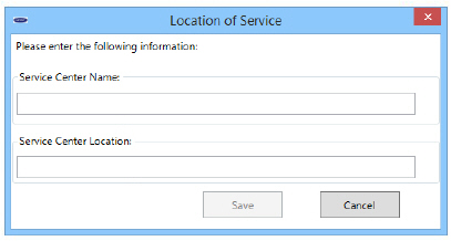
4.A Location of Service pop-up window (Figure 10.7) will appear. Enter the Service Center name and the Location of the service center where the calibration is completed. Click save and a pop-up window reminding user of ice bath temperature will appear click OK to acknowledge and remember to maintain the Ice bath at 0° C (32°F)
Figure 10.7 Location of Service
5.Prepare the ice bath. Refer to the Ice Bath Preparation procedure below.
6.Once temperature stability is ensured submerge the sensors in the ice water slurry without touching the container sides, bottom or each other. Continuously stir the slurry mixture during calibration.
7.Before clicking the Start Cal button, ensure that the Ice bath is at 0° C (32°F) using the calibrated reference thermometer. Click on the start Cal button only after the sensor readings have stabilized and the sensors are within +/- 0.3° C (0.5°F). The readings can be taken at the UnCal column circled below.
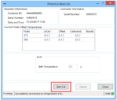
8.After clicking Start Cal (Figure 10.8), the process will proceed automatically taking a maximum of 5 minutes.
9.Continue to stir the ice bath during the testing.
10.Calibration will fail if the stability cannot be achieved or the sensor offset is greater than 0.3°C (0.5°F). Replace sensor and repeat recalibration.
11.Once the calibration has completed, a “Calibrate Complete” pop-up message will appear (Figure 10.9).
Figure 10.9 Calibrate Complete
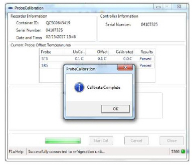
12.Acknowledge the pop-up. The results will then be displayed on the Probe Calibration screen (Figure 10.10).
Figure 10.10 Calibration Results
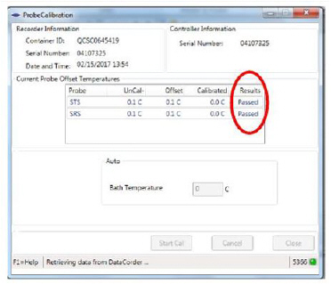
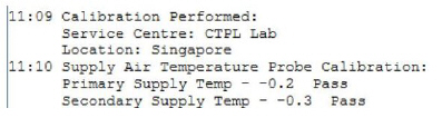
13.After completing the calibration event, download a DCX file and check if all the information is captured (see Figure 10.11). The service center name and location, the results of the calibration and the offset applied will be captured in the DCX file. Ensure that all the information is captured and the event is considered a success when all the intended sensors in calibration have passed.
14.After the completion of the calibration, restore the unit to its original state. It is recommended that calibration is done before the Auto PTI procedure.
Return Air Sensors Calibration
The return air sensor calibration is similar to the supply air sensors calibration.
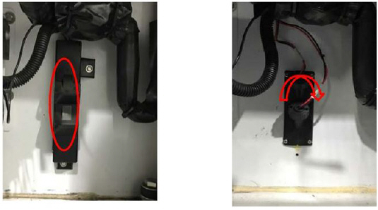
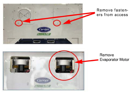
1.Remove both front access panels from the unit by removing 8 fasteners from each panel (see Figure 10.12). Save all hardware for re-installation. On the right side, disconnect the fan motor wiring, loosen the fastener and remove (slide) the evaporator motor from the unit. (Circled).
Figure 10.12 Return Air Sensors
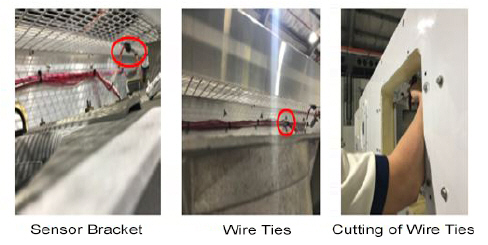
2.Loosen the fastener on the sensor bracket and cut all the wire ties that secure the sensor wiring to the unit (Figure 10.13).
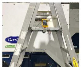
3.Put the ice bath on an elevated platform (i.e. step ladder) of appropriate height. Keep the ice bath level so that the sensor would not touch the side of the container (Figure 10.14).
Figure 10.14 Ice Bath Placement
4.Route the sensors to the ice bath and submerge them.
5.Perform steps 7 through 14 of the supply air sensor calibration procedure.
Ice Bath Preparation Procedure and Equipment
1.Wherever possible, use a thermometer that is regularly calibrated by an accredited test lab.
2.Always use a temperature measurement reference instrument which is of higher accuracy than the device checked, for instance, a thermometer with a rated accuracy of +/- 0.2°C should be used to check a device with a rated accuracy +/- 0.3°C.
3.A thermally insulated container, tub open to atmosphere and large enough to contain crushed ice and water should be used. The tub should be large enough to contain the unit's sensor and the reference thermometer.
4.Enough distilled water should be available to make ice cubes and to set up a proper and stable ice-water triple-point mixture. Prepare ice using distilled water.
5.Pre-cool distilled water for testing.
6.Prepare a mixture of clean ice using distilled water in a clean insulated container. If possible, the person handling should be wearing latex gloves.
a.Crush or chip the ice to completely fill the container. The finer the ice particles, the more accurate the mixture.
b.Add enough pre-cooled distilled water to fill the container.
c.Stir the mixture for a minimum of 2 minutes to ensure water is completely cooled and good mixing has occurred.
d.General, the mixture should contain about 85% ice with the distilled water occupying the rest of the space.
e.Add more ice as the ice melts.
7.Stir the ice water slurry mixture to maintain a temperature 0°C (32°F).
8.Constantly monitor the temperature of the ice water slurry with your reference thermometer. Ensure that the temperature of the bath has stabilized. The criterion for stability generally is to take two readings at 1 minute intervals, and the two readings should give you 0°C (32°F).
Key Points to Note:
1.If the calibration process has failed, check the validity of the sensor by hand warming the sensors to see if there are changes in the readings on the DataLINE screen. The changes should be displayed on the DataLINE screen. If there is Uncal in the download, it means that the calibration process was not completed.
2.Ensure that the set-up (i.e. Ice bath, Sensors, reference thermometer) has reached a stable state before starting the process. Ensure that the set-up is clean and reference thermometer is regularly maintained and calibrated.
3.When undergoing the calibration process, ensure that the sensors do not contact the container and also do not contact each other.
4.Contact your instrument representative if the reference thermometer is not showing correct readings. Having an accurate reference thermometer is important for the process.
5.Calibration should be conducted in pairs. (STS/SRS, RTS/RRS). If the sensor is unable to fall within reading of (+/- 0.3°C / 0.5°F) after stabilizing, replace the sensor and recalibrate the sensors. Refer to the service manual for the sensor replacement procedure.
6.Ensure that DataLINE 3.1 is installed and controller software is at least to the level of 5368 before proceeding with the calibration.
7.Calibration process should be started only after temperature has stabilized for all sensors involved.
8.Record all steps and all appropriate paper work involved with the servicing procedure.
10.3All other ML3 controllers loaded with SWR51xx series SWR53xx below 5368, SWR57xx series and all ML2i controllers
The Probe Calibration screens will be available when the user clicks on the Probe Calibration button on the DataLINE Launch Pad. From each of these screens, the user can perform USDA/Cargo probe calibration using the selected methodology. Unlike with newer 53xx series unit software, calibration for Supply Air and Return Air Temperature sensors is not available.
When DataLINE establishes a connection with a container unit, each calibration screen displays the following information:
•DataCorder (Recorder) information
•Controller information
•Temperature probe/sensor information
•Controls related to the selected calibration option
•Controller software version
The connection status with the container unit is also reported at the bottom of the screen. If DataLINE is not able to communicate with the refrigeration unit, X's will be presented in the data fields.
DataLINE refreshes the calibration screens in two ways:
•AutoRefresh - Every 15 seconds the probe calibration screen automatically updates all data in the “Recorder Information”, “Controller Information” and “Current Probe Offset Temperatures” group boxes.
•F9 - Provides the user with a shortcut for manually triggering the refresh operation.
The user can choose to perform USDA/Cargo probe calibration using either of the two available options:
•Auto - The MicroLink controller in the container unit calculates the offsets for all probes using an assumed ice-bath temperature of 0.0°C (32°F). The user cannot select probes or change the ice bath temperature value. Calibration is performed when initiated by the user after determining the probes are stable at the ice bath temperature.
•External - The user explicitly specifies the offset to be used for each probe that is to be calibrated. Offset values between -0.3°C and +0.3°C (-0.5°F and +0.5°F) can be entered by the user.
By default the following screen is displayed (Figure 10.15). It can also be displayed by choosing the Auto option button if it is not selected.
Procedure:
1.Prepare proper ice bath and ensure that it has stabilized at 0°C (32°F).
2.Place all probes to be calibrated in the ice bath and observe readings on the screen.
3.Once probe readings have reached equilibrium and ice bath is 0°C (32°F), press the “Start Cal” button.
4.Once calibration is complete, the calculated offsets will be displayed when the screen refreshes.
5.“Start Cal” can be pressed to perform calibration again. If calibration is successful, press “Close” to exit Probe Calibration.
Calculated offsets up to ±2.0°C (±3.6°F) are saved. If calculated offsets exceed this value, offsets for those probes are saved as 0.0°C (0.0°F).
The following Probe Calibration screen (Figure 10.16) is displayed when the user clicks on the External option button on the Probe Calibration screen.
Figure 10.16 USDA/Cargo Probe Calibration (External)
Procedure:
1.Check the box in front of the first probe needing calibration to activate the offset entry box.
2.Use the arrows or type an offset value into the entry box to use for the probe. (up to ±0.3°C (±0.5°F))
3.Repeat steps 1. and 2. for each probe being calibrated.
4.Press the “Send” button to calibrate the sensors using the offsets that were entered.
5.Press the “Close” button to exit Probe Calibration.